Challenge: Duty Cycle
Question
- Why power electronics circuits are efficient? In practice, which types of losses occur in power electronics circuits?
- Using a suitable MATLAB model, show how duty cycle control signal can be generated for a simple power converter circuit?
- Explain the difference between VFD and Vector control drive. Can we use VFD method for induction motor in EV application?
Answers
#1
In the earlier days, the control of electrical energy was done mainly using thyratrons, vaccum tubes and mercury arc rectifiers which work on the principle of physical phenomena in gases and vapours, these devices were bulky and consumed a great deal of power to operate. In other words they were not very efficient. The advancement in technologies brought the development of silicon controlled rectifiers (SCR), soon many power electronic devices emerged like GTO, IGBT, SIT, MCT, TRIAC, DIAC, IEGT, IGCT and so on. These devices are rated for several hundred volts and amperes unlike signal level devices which work at few volts and millamperes. These devices are made to work like switches having 2 modes: ON and OFF.
The power electronic devices alone are not that useful in practical applications and hence require to be designed in a circuit along with other supporting components. These components allow the power electronic switches to achieve the desired output, this includes the firing circuit and the feedback circuit. A control unit takes the feedback from the output using sensors and compares it with the references and accordingly gives input to the firing circuit. The firing circuit is basically a pulse generating circuit which gives pulse output in a fashion so as to control the power electronic switches. The final result is that the load receives the desired electrical power and hence delivers the desired output. These power electronics deals with the conversion and control of electrical energy with the help of power semiconductor devices that operate in a switching mode and therefore the efficiency of the power electronic system may approach as high as 98-99%. A typical example of this system is the speed control of motors.
Power Losses
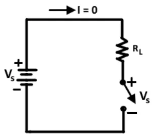
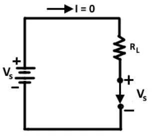
In an ideal switch, the power loss generated is the product of current passing through the switch and the voltage across the switch. When the switch is OFF there is no current passing through it (although there is a voltage `V_S` across it), therefore there is no power dissipation. When the switch is ON it has a current through it but there is no voltage drop across it, so again there is zero power loss. Also it is assumed that for an ideal switch the rise and fall time of current is 0, that is the switch changes from OFF state to ON state and vise versa instantaneously, therefore the power loss during switch is 0. This was the case of an ideal switch.
Switch in Open Condition (OFF),
Switch in Closed Condition (ON),
An actual switch such a bipolar junction transistor (BJT) has 2 major sources of power loss, they are: Conduction loss and Switching loss.
Conduction loss
When the transistor is OFF, it carries a leakage current `I_(LEAK)`. The power loss associated with leakage current is `P_(OFF)=V_SxxI_(LEAK)`. However since the leakage current is quite small and does not vary significantly with voltage, it is usually neglected and thus transistor power loss is essentially zero. When the transistor is ON, it has a small voltage drop across it. This voltage is called saturation voltage `V_(CE(SAT))`.
The transistor power dissipation due to saturation voltage is `P_(ON) = V_(CE(SAT))xxI_C ->(1)`
Where,
`I_C = (V_S - V_(CE(SAT)))/R_L ~~ V_S/R_L`
`(1)` gives the power loss due to conduction if the switch remains ON indefinitely. In a power electronics application the switch is turned ON and OFF in a periodic manner. Therefore the duty cycle must also be considered, duty cycle is the percentage of the cycle in which the switch is ON.
`d = t_(ON)/(t_(ON)xxt_(OFF)) = t_(ON)/T`
`P_(ON(avg)) = V_(CE(SAT))xxI_Cxxt_(ON)/T = V_(CE(SAT))xxI_Cxxd`
Similarly,
`P_(OFF(avg)) = V_SxxI_(LEAK)xxt_(OFF)/T`
Switching loss
In addition to the conduction loss, a real switch has switching losses because it cannot change from one state to the other instantaneouly. A real switch takes a finite time to turn ON and OFF. These times not only introduce power dissipation but also limit the highest switching frequency possible.
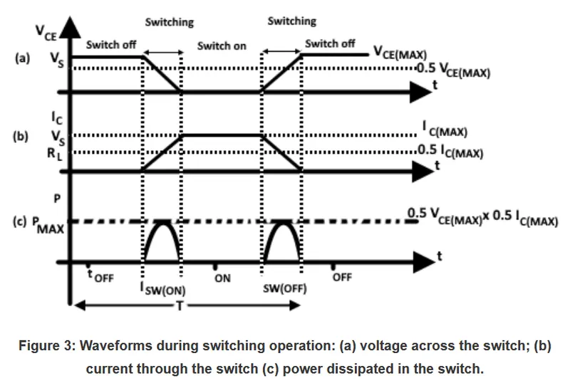
The switching losses typically contribute a significant amount to the total system losses. During the transition interval both the current and the voltage across the switch are substantially larger than zero which leads to a large instantaneous power loss.
#2
A simulink block diagram of a simple buck converter circuit with duty cycle control is shown below,
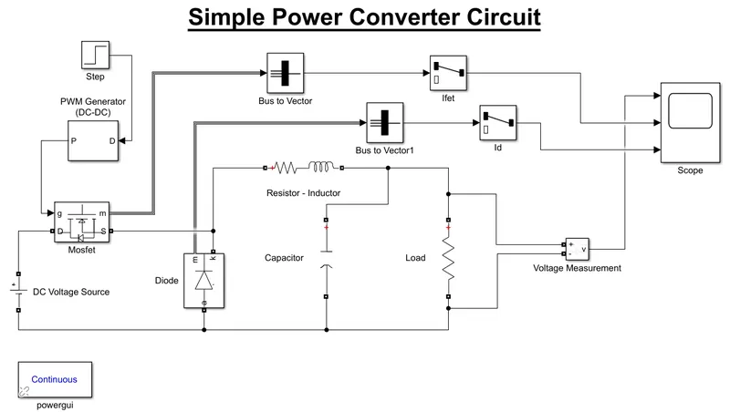
The above converter is very simple and straight forward buck converter. It consist of a mosfet whose gate is controlled through a PMW signal from a pulse generator. The DC voltage source is rated at 200 volts and is connected to the drain of the mosfet and the source is connected to the load via and LCR circuit. The diode prevents reverse flow of current The load resistance is rated at 10 ohms. The potential difference across the load is measured using a voltage measurement block and the output signal is given to a scope. A selector with bus to vector is used to obtain the current measurements from the mosfet and the diode and the signal is given to the scope.
Pulse generator parameter is shown below
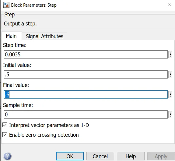
Shown above is the block parameter of the step block. Here the final value depicts the duty ratio. The final value-0.6 represents 60% of the duty cycle and if 45% of duty cycle is required then the final value is 0.45 likewise. The step block is used to set the duty ratio and the step time (time period of the cycle) and gives the signal to a DC-DC PWM Generator which produces the required PWM signal. Here the PWM generator is set to a switching frequency of 10,000Hz.
Results,
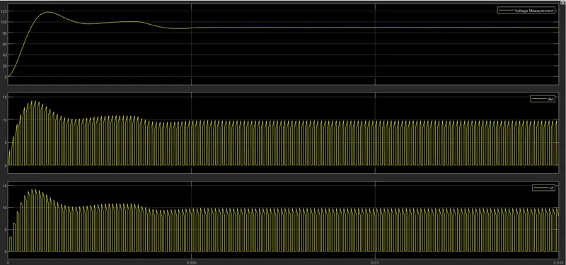
With 45% duty cycle the output voltage is 90 volts,
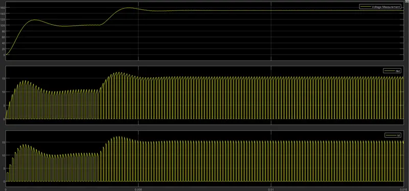
With 75% duty cycle the output is 150 volts,
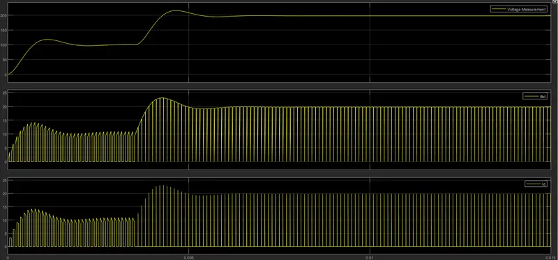
With 99% duty cycle the output is 198 volts,
#3
Variable Frequency Drive (scalar) and Vector Control Drive
A variable-frequency drive (VFD) is a type of motor drive used in electro-mechanical drive systems to control AC motor speed and torque, this is done using one of two control methods - Scalar control or Vector control.
Shown below is the different VFD control platforms,
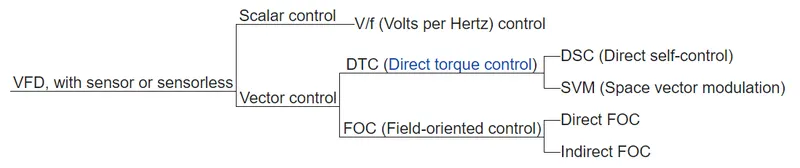
A scalar is a quantity that has only magnitude, such as mass or temperature. A vector is a quantity that has both magnitude and direction, such as acceleration or force.
Scalar control methods for VFD work by optimising the motor flux and keeping the strength of the magnetic field constant, which ensures constant torque production. Here both voltage and frequency of the power to the motor is varied in order to maintain a fixed constant ratio between the two, so the strength of the magnetic field is constant regardless of the motor speed. Speed regulation is only in the range of 2% to 3% of rated motor frequency, therefore not suitable for precise speed control applications.
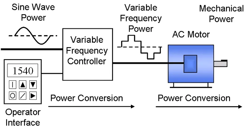
Variable Frequency Control Illustration,
Control process of Scalar control method,
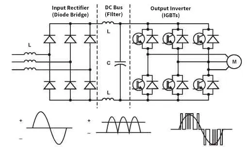
In the above figure, AC power is conveterd to DC through rectifier. The rectified power is then filtered and stored in the DC bus. The inverter converts it back to AC power with proper frequency and voltage via PWM.
Vector Control, also called field-oriented control (FOC), is a variable-frequency drive (VFD) control method in which the stator currents of a three-phase AC or burshless DC motor are identified as two orthogonal components that can be visualised with a vector. One component defines the magnetic flux of the motor, the other the torque. Here the two components are controlled independently, each with its own PI controller. FOC is used to control AC synchronous and induction motors. FOC was actually developed for high performance motor applications that are required to operate smoothly over the full speed range and generate full torque at zero speed, and have fast acceleration and deceleration. Vector control methods are more complex than scalar control methods.
Control process of Vector control method,
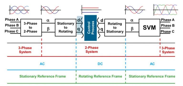
Vector control converts 3-phase currents in a stationary reference frame to a 2-phase system (consisting of a flux component - d and a torque producing component - q) with a rotating reference frame. Here, the torque-producing current (q) can be independently controlled to ensure maximum torque production. The system is then transformed back into a 3-phase system in a stationary reference frame for the output to the motor.
Scalar control method is not suited for EV application as they cannot provide precise speed control. On the other hand vector control methods offer significant benefits, like, the open-loop vector control enable the motor to produce high torque at low speeds and the closed-loop vector control allows the motor to produce upto 200% of its rated torque at zero speed and it also provides very accurate torque and speed control. For these reason it can be concluded that for EV application vector control methods are best suited.