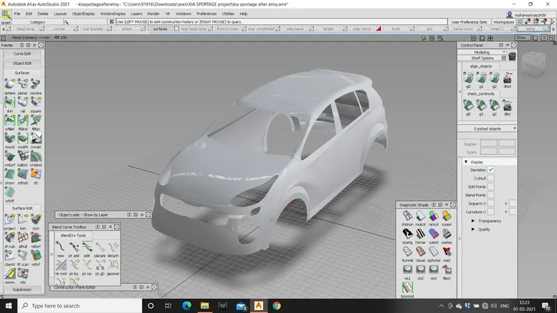
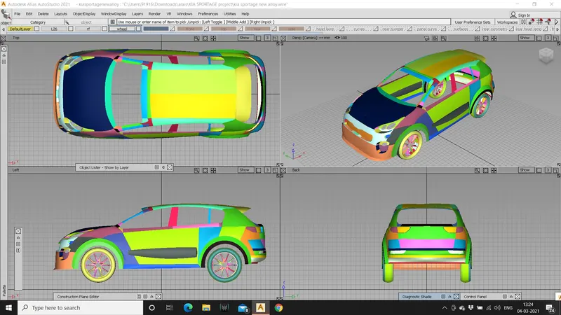
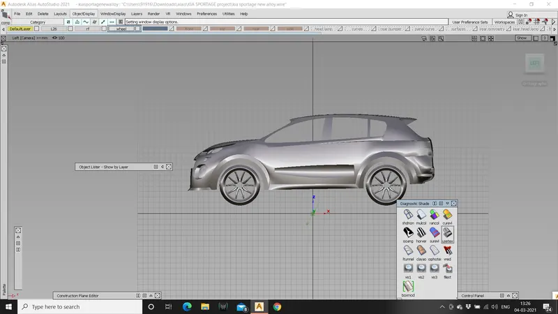
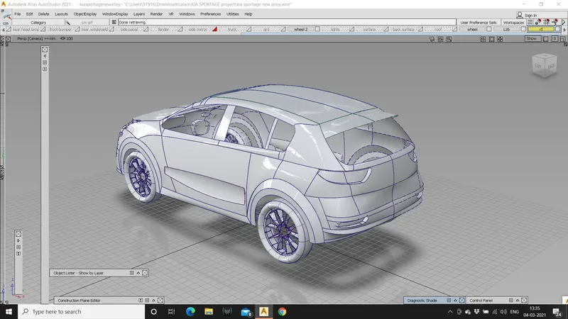
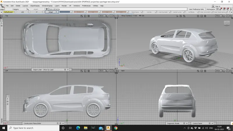
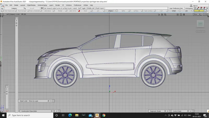
Technical Surfacing Kia Sport age 2016 using Autodesk Alias
Title of project: concept modelling of KIA sport age 2016 model
Objective: to create entire KIA sport age surface model with better continuity using given reference images
Tools used:
Freeform blend tool, CV curves, line, skin, align tool, trim, project, intersect, extend, detach tool, and transform tools, fillet, rail command, Ms Draft, duplicate curve, trim convert, etc.
Introduction:
Introduction to surface continuities and its types
Continuity is the smoothness of the junction i.e., two mating curves. Continuity is the condition that the more smoothly the adjoining surfaces flow
Generally there are 4 types of surface continuities i.e., we can have surfaces coming in contact in 4 different ways.
They are:
- G0-position (touching)
- G1- tangent (angle)
- G2-curvature (radius)
- G3-acceleration (rate of change of curvature).
- G0-position (touching) continuity:
This is less smooth type of joint with common end point. This position is the only condition to satisfy the joint.G0 is the point continuity when one curve touches the other and shares the same boundary
- G1- tangent (angle):
One can’t have G1 continuity unless you have G0 continuity.it is also called as second order of continuity i.e., to faces meet along a common edge at a tangent plane they share a common angle. The best example for G1 continuity is a fillet.
- G2-curvature (radius):
G2 adds another order that must match across our pair of curves. For G2 it must a tangent to the curve and have the same curvature a point where they touch I.e., the input geometry must now be curved s well so the input containing a straight line can’t make a G2 curvature.
- G3-acceleration (rate of change of curvature):
G3 continuity includes the concept of acceleration of the curvature; the amount of change in the curvature over the length of the curve.G3 is looking for balance on the rate of curvature.
Description:
- Open auto desk alias and choose class a surfacing.
- Change the preference as per the requirements by preferences > construction options. Select the tolerances to be added.
- Import the canvas image by going to file > import canvas image > always create new layer.
- After importing the canvas image divide assign each view of the image to a different layer for better understanding of the model.
- Create a dimension box with the given dimensions in the canvas image and assign it to a certain layer. This makes sure that the model won’t exceed the limits.
- Start by creating the base of the model on which the entire model can be generated easily.
- Start by fender area of the car and create curve using CV curves and transform the curve as per the requirements.
- Starting from the bottom create the alloy wheel.
- To model an alloy wheel we need a surface to build on, to create that surface create a circle that traces the alloy wheel in the canvas image.
- Create hypothetical curves and transform them as per the requirements.
- Crete a plane and give it some crown and then project the hypothetical curves that are generated on to the surface
- Now you have a surface where further surfaces can be built on.
- Create the details of the alloy wheel using CV curves and give some shape to the curves so that it exactly matches the alloy wheel in the canvas image.
- Use “MS draft” to create the surfaces that are at a certain angle.
- Using the surfacing tools like “square” “rail” to build the surfaces and trim the extra surfaces for caner look.
- To achieve better surfaces always intersect and then trim the surfaces so that you won’t face a problem while applying fillets.
- Create tyre volume using skin command and give certain crown to achieve the shape of the tyre.
- Assign the alloy wheel to a different layer ,
- Coming to the body of the car create the curve network to build surfaces.
- It’s better to create curve network for each part in separate layer which enhances better working environment.
- Create the half of the car so that another half can be mirrored at the surfacing phase.
- Create the front bumper in a layer using CV s and align the curves to the center at tangent so that the continuity won’t create any problem while mirroring the model.
- Create a fender area and match the front and top views in the model.
- Complete the entire model using proper curves and ensure that the curve network in good so that the surfaces don’t create a problem.
- Some curves history is to be deleted for better manipulation of the CV s in the model.
- Trace the windshield from the curves so that at the end they can be projected and trimmed on the surfaces.
- Trace the front and rear head lamps and assign them to different layer at the end they can be projected easily.
- Trace any further details if need to make the sharp model.
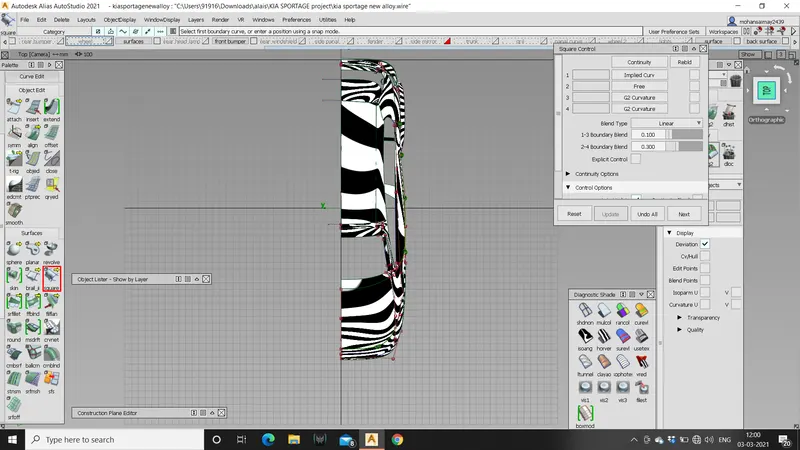
- Now the surfacing part using square tool to create surfaces creates the surfaces where four sided patches are available.
- Always try use four sided patch layout to create surfaces so that it eases the manipulation of surfaces.
- Use “align” command to forcefully align the contact vertices to achieve the continuity.
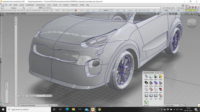
- Create the sharp model by creating every surface and make the model ready for filleting.
- Apply fillets wherever needed to achieve the smoother surfaces and for better appearances.
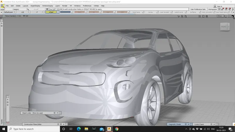
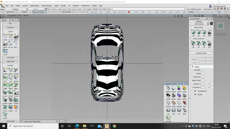
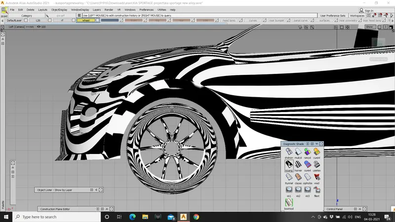
- Check for surface continuity using zebra stripes if any surface is not good try to modify or delete the surface and create the new patch.
- Finally assign all the surfaces to a different layer and create symmetry by layers>symmetry>on.
- Create geometry of the symmetry using layers>symmetry> create geometry.
- Pan and tumble the model for appearance and save the final model.
- Hence the entire the surface model of the KIA shortage is crated.
Design methodologies:
CV curves: CV curves are contact vertices in which the contact points can be manipulated by increasing and decreasing CV s. CV curves are basic form of structure building curves these are easy to work on.
Blend: blend tool is used to create a blend between curves and can be easily manipulated.
Extend: extend command increases the spread of the surfaces or the curves.
Skin: skin command is a surface tool which creates surface between two curves or surfaces and will have a proportional crown which enables to give some curvature to the surface.
Transform tool: transforming tools are SCALE, MOVE, ROTATE. These enable the designer to manipulate the curves according to the requirements.
Align tool: align tool is used to align two curves or surfaces at a curvature.
Trim: trim command is used to trim extra surfaces under a specific closed structure.
Project: project is tool used to project the curves on the surface which is called as COS (curves on surface).
Intersect: intersect is a command used to intersect two or more surfaces to single surface.
Detach tool: detach is used to detach the curve or surface at certain point.
Surface fillet: surface fillet is secondary surface which is used to create smoother edges in the surface model.
Rail: rail is surface tool in which surface can be created using two curves one as a generation and other one as a curve. Rail command is also used to create four sided patches it is very effective tool in creating surfaces in alias.
Ms Draft: Ms Draft is surface tool used to create surfaces at certain angles and can be easily manipulated.
Duplicate curve: duplicate curve is used to create curves from a surface and very effective to work with
Freeform blend tool: free from blend is surface tools used to create a blend between two curves or surfaces.
Trim convert: trim convert is used to trim and create surfaces at the same time which creates better continuity while applying surfaces.
Conclusion:
The surface model of KIA sport age is completed as per the given dimensions.
- for better surfaces always match the CV s between curves on which surfaces are built.
- Avoid creating surfaces from trimmed edges. Always try to intersect and then trim.
- Ensure tangency at the centre line for better continuity of the surfaces.
- Always try to use less contact vertices while creating patch layout.