Challenge 8 : Concept Modeling of Seats
CONCEPT MODELLING OF SEAT
OBJECTIVE :
To construct the design of seat render
INTRODUCTION :
A car seat is the seat used in automobiles. There are mainly two types of seats such as bench seats and bucket seats.A bucket seat is a separate seat with a contoured platform designed to accommodate one person, distinct from a bench seat that is a flat platform designed to seat up to three people. Individual bucket seats typically have rounded backs and may offer a variety of adjustments to fit different passengers.
A car seat consist of three parts. head support back support and thigh support. In this project the design of bucket seat had been done consist of a head support back support and a thigh support using Autodesk alias softwrae. There is blue print of side view and a perspective view of seat, so we have to visualise it in 3D view and accordingly design the model.
DESIGN METHODOLOGY :
- Import the image of seat consist of side view and perspective view.
- Analyse the image and make dimensional box for bottom part and back support part separately.
- Decide the part which have to be drawn first.
- From the orthographic picture we have to visualise it in a 3dimensional view.
- Since car seat is symmetric we have to draw only a half part. Comparing the side view with the perspective image starts to make surfaces accordingly.
- For making surface of back support it self we have to split the part into side, back, front and top surfaces. And connect every side in collective manner with good continuity and good collective shape. In making bottom support also follow those steps.
- For making curves use tools like cv curve duplicate curve etc, and for making surfaces use square surface rail surface, skin or ms draft etc.
- For getting good quality surface we have draw the curves with good quality.
- Finally we got a sharp edged design of seat for make it smooth by fillet tool.
DESCRIPTION :
in case of bucket type single seating car seat, the major parts are head support bck support and bottom support.We have to design them separately according to the sizes that should decide by ourselves, like how much size should be there for the head reast while the back support has some size and accordingly the bottom support.
Head rest:
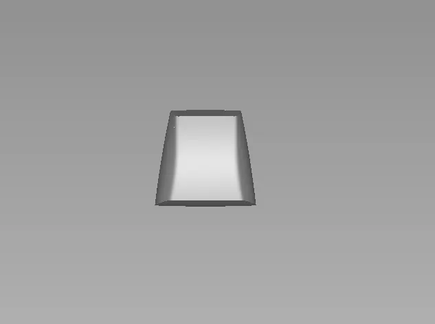
Bck support:
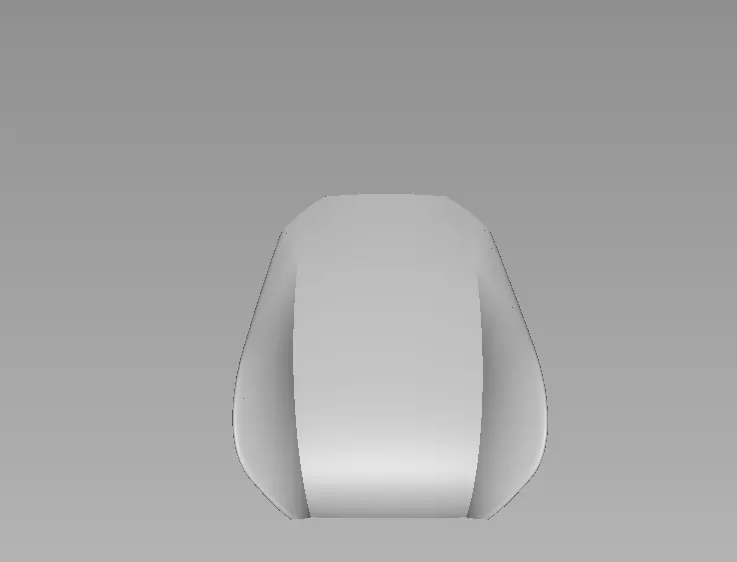
Bottom support:
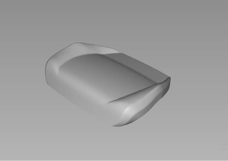
From a 2 dimensional side view image of a seat we have visualise it in a perspective view and draw the design and make it in a 3 dimensional shape. While making the surfaces of each part we have make sure that the flow of surfaces should be in correct manner like if we see the design in any view it should be like seeing real model.
For making the design we have lot of tools in Autodesk alias
Cv curve and Blend curve tool :


For every designing in alias the basic tool is which a designer use is cv curve tool. We can draw any shape of curves using this tool and by connecting the curves we can make the surfaces.
Blend curves can be used to create a single curve that accurately matches a series of edges or Curves-on-surface. We can edit the tightness of the blend by using edit tool inside blend tool.
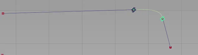
The above figure shows the blend curve.
Duplicate :

Duplicate tool is used to duplicate the object with same as its shape and size. The operation is done by just pick the object(s) you want to duplicate and then click on duplicate tool under curve edit.
Rebuild curve :

This tool is same as duplicate tool, in this case we obtain the curve with same shape but with different mathematicl properties. After rebuilding, automatically switch to the smooth tool to allow you to smooth the resulting curve.
Atach Detach and Extend :


Attach and detach tool as name says they are used to attach or detach the surfaces or curves at different different points.
Extend tool is used to extend the length of a surface, curve or a curve on surfaces by extending the edge without changing its origin.
Align tool :

Align tool is used to forcefullu align the surface or curve over the other curve or surface.The Align tool moves or reshapes a curve or surface to achieve positional, tangent, or G2 curvature continuity with another curve or surface. We can decide the continuity in which what we need on that surfaces.
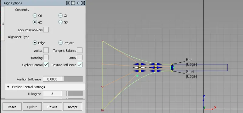
The above figure shows just an example of aligning a surface over other.
Query tool :

As the tool name says query tool used to know the information abouth curve surface or curve on surface. We got the information of last operation that we had done on that surface or curve. The operstion is done by just click on the query tool and then click on the surface or curve then we got the information.
Plane tool :

Plane tool is comes under surfaces. In which we got preset structures such as cylinder, cone, sphere, torus, cube plane.
Square, Rail and Skin surface tool :
These tools are used to make the surfaces. Each tool has there own speciality.
In the case of rail surface we need minimum two curves oru two surface edges or one surface edge or one curve. And we can make surface on three sides by using one generation and two curve or for four side we can use 2 generation and 2 rails. We can apply different continuity on different sides.
In case of square surface tool we need 4 sides to make the surface. The side may be curves or surface edges or curve on surfaces.
Use the skin tool to create a surface by connecting a set of profile curves.
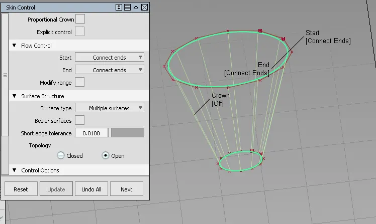
The above figure shows the skin surface.
Surface fillet tool :

Fillets create a transition surface between two surfaces or sets of surfaces.This tool makes sharp edge surface into smooth.
Free form blend :

Free form blend enables you to create a transitional surface based on two input contact lines.
Multi surface draft tool :

This tool enables us to create one or more ruled surfaces by pulling a group of surface curves at an angle to the normal of the original surfaces. We can give the angle and length of the surface according to our need.
Project and Trim :

Project tool used to project curve or edge of surface on othe surfaces. By using trim tool we can trim out the portion that had been intersected by projected curves means curve on surfaces.
By intersect tool we can intersect two surface by means of intersecting the surfaces by extending the surface over other.
There is an another trim option that is trim converter. By using this operation we got 3 surfaces such as main surface and separated 2 surface. And we can use the surface for other operations.
Nurbs to bezier tool :

This tool enable us to split the multispan nurbs surface into single pan bezier surfaces with continuity.
Surface continuity tool :

This tool helps to check the positional , tangent plane and curvature continuity between surfaces.
Diagonostic shade :
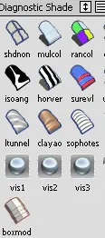
This enable us to visualise the model in different manners. There are options like multi colour , shading off horizontal or vertical diagonostic shader etc.
CONCLUSION :
This project improve my knowledge on tool operations in Autodesk alias and also improves my ideas on visualising the orthographic view in 3 dimensionsional structure.