Challenge 6 : Concept Modeling of Side Fender
DESIGNING OF SIDE FENDER OF VEHICLE
OBJECTIVE :
To construct design of side fender of vehicle from a single view.
INTRODUCTION :
Fender is a part of an vehicle which frames a wheel well. Its primary purpose is to prevent sand, mud, rocks, and other roadspray from being thrown into the air by the rotating tire.
In this project the main objective is to design a fender by its front view itself. By analysing the view we have to visualise it in a complete 3D structure and make surfaces with good quality and continuity.
DESIGN METHODOLOGY :
- Import the blueprint of the side fender.
- By analysing its structure decide the curves, shape of the structure and decide the order of patches and starts to draw by using convinient tools.
- visualising image in a 3D way is important in this scenario.
- Make good quality curves accoding to its flow and make good quality surfaces with good continuity.
DESCRIPTION :
As mentioned in objective the aim of this project is to design the fender of a car by a single view of it. For drawing the structure i have to visualise the 2D picture in a 3D manner. According to the shadow of light we have to deside it slow of shape and make surface accordingly.
There are many convinient tools which are makes this designing work effortless they are :
Cv curve :

for making good quality surface we should need good curves. Here for tracing the blue print and to draw the structure we use the tool Cv curve. We can adjust the shape direction etc of a Cv curve accordingly withe structure 0f what we need. Cv curve are the base of a surface, so we have to draw the curves perfectly according to the structure.
Blend :

Blend tools are used when there is a need of connecting two curves whethere it is curve or straight connection it can be easilly done by blend curve. we can edit the angle and itstightness by edit command. In this project i have used blend curves in different sections .
Attach and Detach :

As the name say this tools are used to attach or detach a curve or a surface. just like trim operation we can separate a surface into two by detach tool or connect two surfaces or curves.
Extend :

Extend tool is used to decrease or ncrease the length of a curve or surface without affecting its origin.
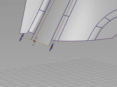
The above figure shows just an example of using bthe extend tool.
Align :

Align tool is used to align the continuity of surface edge with other surface. We can make continuity by forcefully using align tool.
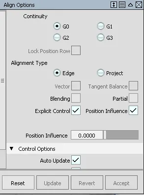
As shown in the above figure we can make continuity forcefully by G0, G1 tangent, G2 curvature and G3 curvature. and by explicit control we can change its degrees and spans. And there are more options to make continuity according to our need.
Query :

Query tool is used to know the information of a surface. And we get the last operation that we have done on surface. And this helps us to change or edit the previouslydone operation on a surface.
By clicking the query tool and just click on the surface that we need to get the info we can use this tool convininently.
Smooth :

smmoth tool works as its name says that is to improve the smoothness of surface or curves by harmonizing Cv distance and changing the angle of hulls.
Rail and Square :

These tools are used to construct the surfaces according to the curves we made or by the surface edges.
Rail surface is used when there is one generation and one rail or 1 generation and two rail or 2 generation and two rail. Basically we need just two curve or surface edge and curves to make rail surface.
Square surface tool are used only when there is four sides. We can give the continuity as our requirements.
Surface fillet tool :

Fillet tool is used to make transition surface surface betwwen two surfaces. To make the edges of surface smooth we use this tool.
Free form blend tool :

This ffblend tool helps us to create transition surface between two curves or two surface edges.
Project and trim :

To cout out a portion from a surface we use proect and trim tool. This tool are connected to each other.
There is an another option that is trim convert. By this we got separate portion within the surface. We can edit the surface for future or we can simply delete the part which we don't need.
Diagonostic shades :
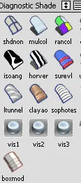
This window has different tools to visualise our design in different shades. we can check for the flow of surface and and its discontinuity etc by just viewing different shades.
CONCLUSION
By doing this project i got to know more about visualising a 2D image into a complete structure, and draw the design almost perfectly by its surface continuity and shape.