Challenge 6 : Concept Modeling of Side Fender
Tittle: Side fender modelling
Objective :
To build a concept modelling of side fender using curves and surfaces
Introduction:
Fender is the American English term for the part of an automobile, motorcycle or other vehicle body that frames a wheel well (the fender underside). Its primary purpose is to prevent sand, mud, rocks, liquids, and other road spray from being thrown into the air by the rotating tire. Fenders are typically rigid and can be damaged by contact with the road surface.
Early automobile fenders set over the wheels to prevent mud, sand and dust being thrown on to the body and the occupants. Fenders typically became a more integral part of overall auto bodies by the mid-1930s.
One of the primary functions of a fender is to keep dirt, dust, and road debris away from the wheel and front braking system. Many have small flaps or wings that are designed to enhance this protective function.
Autodesk Alias is used in automotive design for generating Class A surfaces using Bezier surface and NURBS modelling method.
Design methodology:
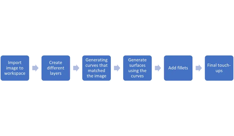
Description:
1) Import the image
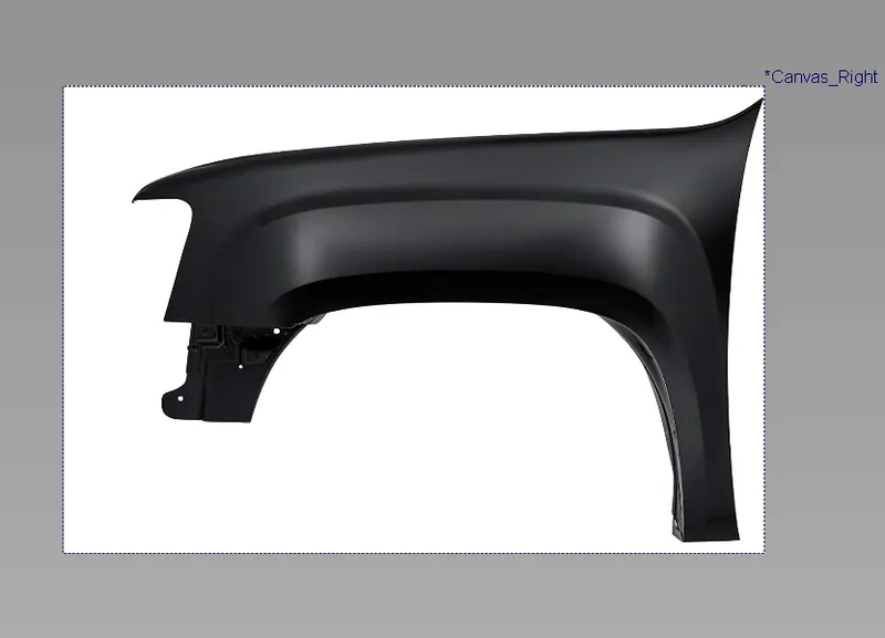
The image of the fender will help us to build the concept model of the fender. Steps for importing Image File -> Import -> Canvas Image -> Go Scaling the Image: After placing the image in appropriate layer the blueprints of the fender will be scaled down to appropriate size so that it can be positioned accurately with respect to the other views. This will help in generation of curves at appropriate places and with desired shape of the blueprint. Steps to scale the image: -> Press ad* shift along with clicking and holding the left mouse button. -> Select Pick object - Select the image -> Press ctrl shift along with clicking the middle mouse button -> Select Scale -> Hold left mouse button and move up and down to scale the image larger and smaller.
Steps to move the image: Palette -> Transform -> Move. The image is given some amount of transparency so that the curves can be traced easily on it at required positions Steps to set transparency. -> Press shift ctrl along with clicking and holding right mouse button. -> Select plane editor. -> Set the value of the transparency level for the different views of the image in it
Curves
Generating the curves to trace the required shape of the fender. After placing the image at required positions the curves are traced on it to give desired shape of the fender: Cv Curve - It lets to create new NURBS on the scene by placing CVs. In order to join curves at few places blends feature is used to give desired shape. Steps for showing blends bar-Palette -> Blend -> Blend Curve Toolbox -> New Curve Trim At few places the curves are trimmed to remove curves at certain places where it is not required. Steps to perform curve trim: Palette -> curve edit -> crvsct -> Select the curve -> click on "GO" present in bottom right corner -> select the curve where you want the portion of the original curve to be removed. The final view of the curve network which was build by using the features in curves is shown below:
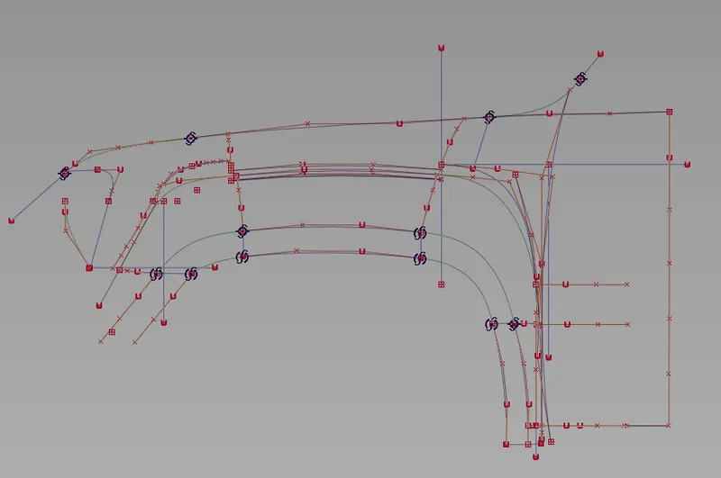
major used tools
Tools Used:
- Import Canvas
- Scale
- Move
- CV Curve
- Pick Curves, CV, Object
- Align
- Duplicate
- Extend
- Blend
- Blend Edit
- Surface
- Project
- Trim
- Draft
- Intersection
-
Major Tools:
Draft:
Select the curve or the surface border which needs to create the draft then edit the options to adjust the angle and length of the draft.
Intersection:
Select the first surface that needs to be intersected and give go, then the second surface.
Align: (Curves and surfaces)
Select the Curve Which needs to be aligned first then select the curve to which is master (reference curve).
Project:
Select the surface on which need to be projected, then select the curve which needs to be projected.
Extend:
Select the curve which needs to extend then use the arrow (will appear at the end of the curve) and drag to extend or decrease.
By using the extend tool it is possible to extend the surfaces also (In this project it is used when the rail surfaces are not generated as required).
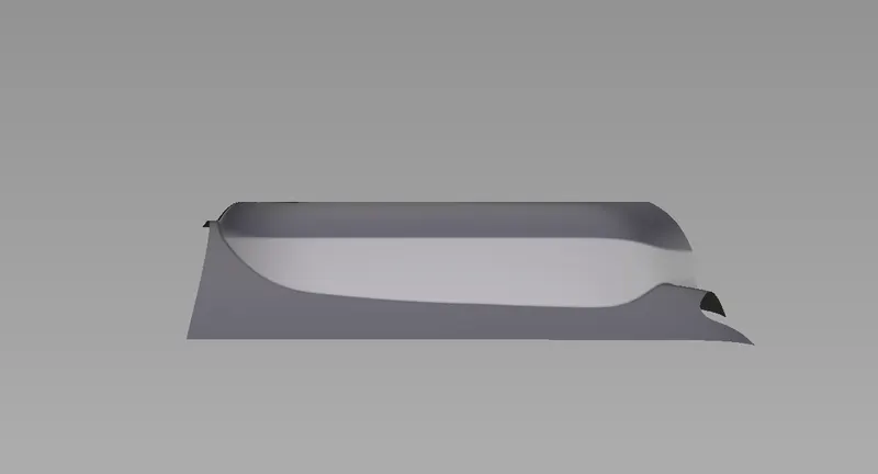
Images of Side Fender models:
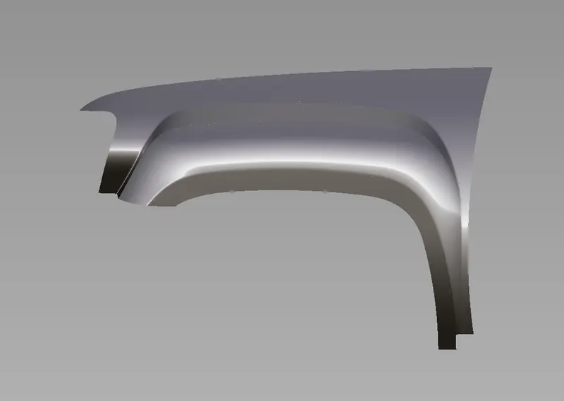
top
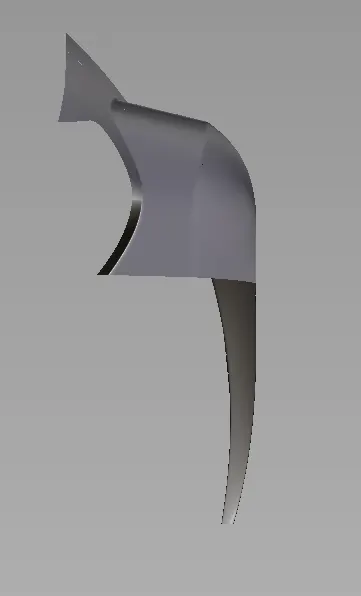
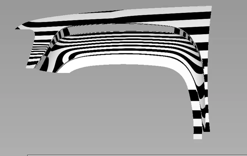
To check surface fine
conclusion
The given component is modeled using the concept modeling method successfully.And its very useful to learn varoius way to create the surface of fender.