Challenge 5 : Concept Modeling of Car Bumper
Concept Modelling of Car Bumper
INTRODUCTION
Concept modelling-
CAS modelling or concept modelling is modelling where the 3D data starts to take shape. It is a crucial part of the process as everybody involved in the design process depends on this to actually visualise, how the design has come out, the shape and feel of it, and to inculcate the design features and what and what not to update.
This process starts from the point where the design has come up to a point of finalization and ready to go ahead.
Surface-
A surface, as a term is most generally used is the outermost or uppermost layer of a physical object or space. It is the portion or the region of the object that can first be perceived by an observer using the senses of sight and touch and is the portion with which other material first interact.
Bezier and Nurbs surfaces-
ICEM surf uses Bezier math to construct patches and curves. The good thing about Bezier math is that patches are smooth and haven’t any internal continuity breaks, essential for class A quality. Bezier (NURBS) math used by Alias.
OBJECTIVE
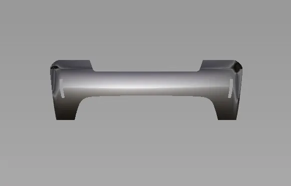
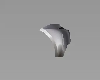
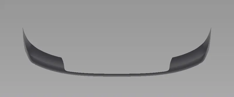
The main objective of this project is to follow the steps or methodology for making a proper concept model of a car bumper (front and rear).
METHODOLOGY
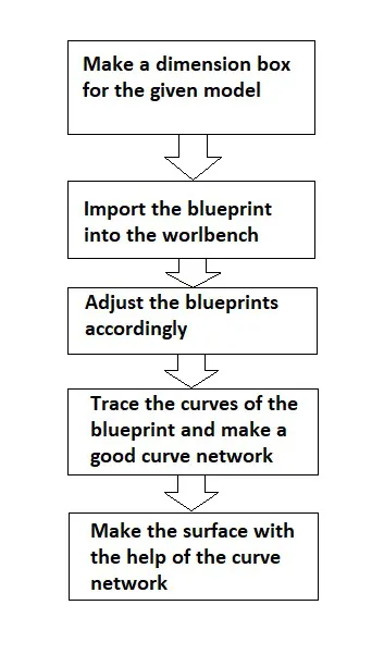
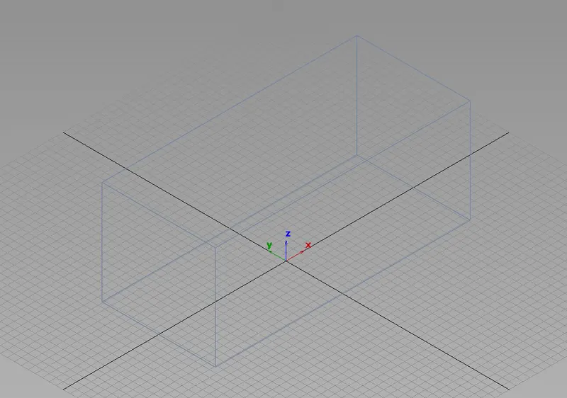
Before importing the blueprint create a dimension box with the proper dimension so that the blueprints could be aligned accordingly.
Then import the blueprints of the model.
After importing the blueprint, adjust all the blueprint accordingly.
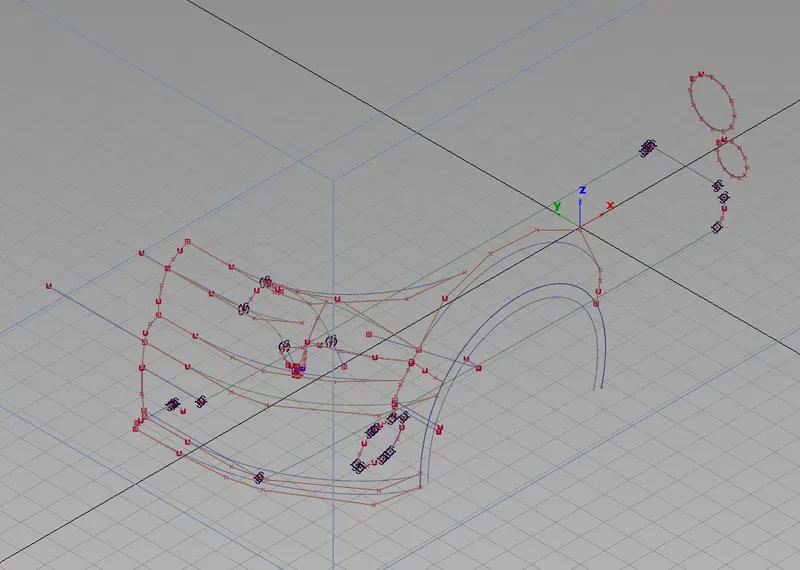
Trace the curves accordingly of the blueprint from all the views and create a good curve network for better surface.
Then using the surface tools and the curve network, create the surfaces.
DESCRIPTION
Car model-
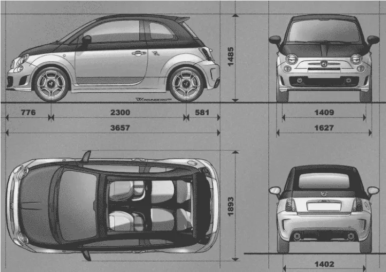
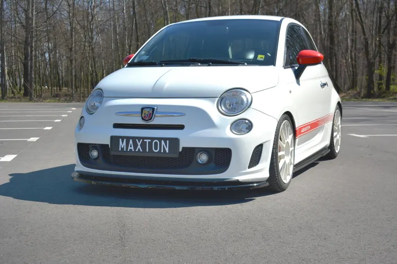
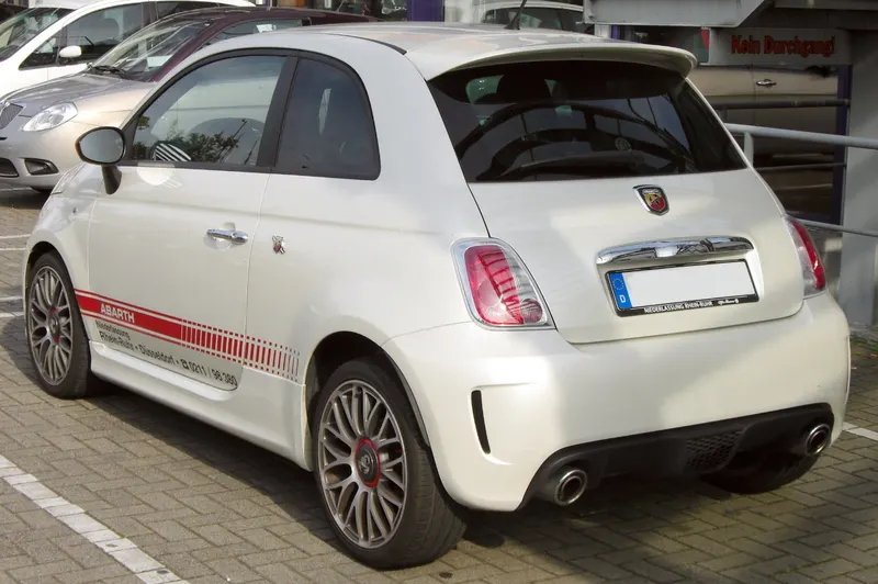
First step is to create a dimension box so as we can import the blueprint and model it within that that particular dimension
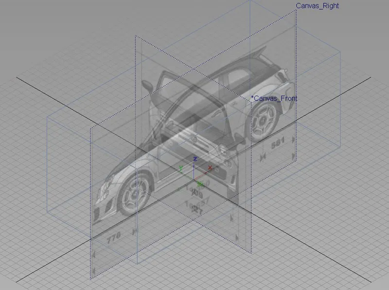
To build the curve network we first have to import the sketch on a new canvas plane and according to the views. To import a picture of a new canvas plane-
-
Click the window view you want to load a picture file into.
-
Choose file – import – canvas image. Click on tiny box icon to open the option box.
-
Set layer type to image.
-
Tick on always create new canvas.
-
Use the file browser to pick out the image file you would like to load and click on select.
Front bumper-
Rear bumper-
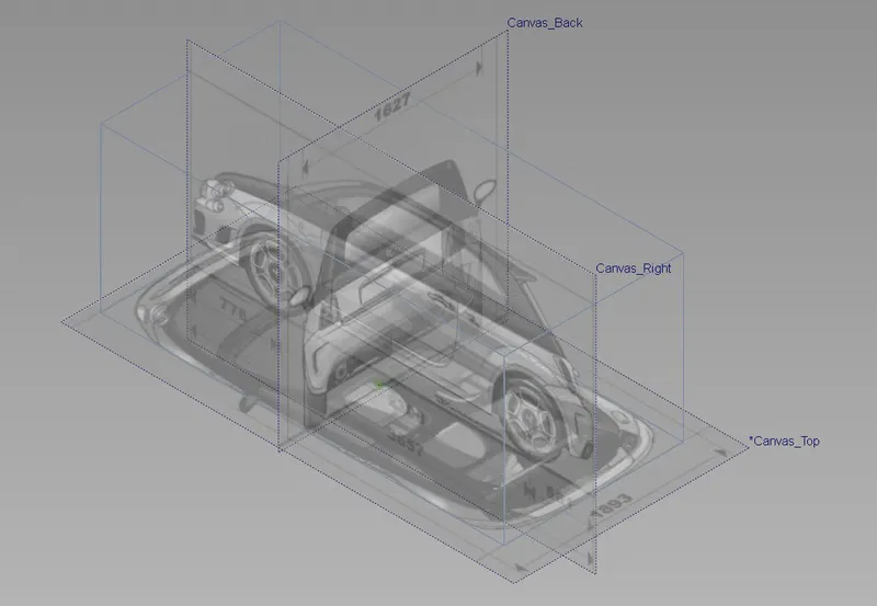
Then create layers for the canvas. Layers are like folders in which you can keep/assign your data and whenever required you can hide/unhide to access more space on the screen.
Assign the canvas of different views of the blueprints to different layers.
Start tracing the curves according to the visualization
In the palette in the curve option there are two types of curve we mainly use.
Ep curve- it already have a set of CVs inside the curve.
CV curve- lets you create NURBS curves.
Then there are two other tool box which is used.
Blend curve tool box- helps to form a perfect blend between the two curves.
There are numerous transform tools in the palette which is used here. The primary tools are move, rotate and scale.
While making the curve network for concept modelling stage check for the lighting and using our visualization make the curve network.
Front bumper-
Rear bumper-
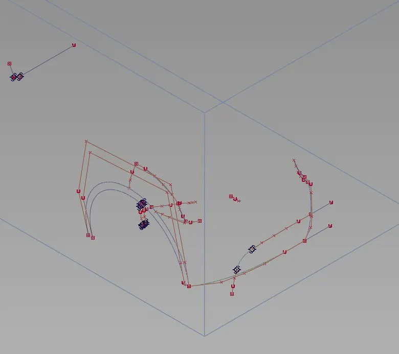
Curve based surface tools will help you produce the surface of the model. Some of tools used are
-
Skin- Create a skin across multiple curves.
-
Rail- Extrude profiles freely or on path curves to make sweeping surfaces.
-
Square- Needs 4 side or 4 connecting curves to create a surface.
Trimming is also done in alias. Numerous CAD frame works after a surface. In Alias there is a middle step required for trimming, the formation of ‘curve on surface’.
Tools for curve on surface (COS)- Project, Intersect.
Project tool will project the curves on to a surface.
Then using the trim tool we remove the extra surfaces.
There is a tool named Align. It is used on a repeated basis. Align tool is used to alter and achieve continuity on the surfaces that have tight tolerances and doesn’t follow the predicted curve network. In this particular case Align tool is used to precisely control certain CV’s to get continuous surfaces.
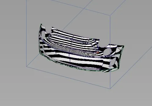
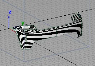
To check the flow of surface or the continuity of surface use the horver shader (zebra stripes). It can be viewed horizontally and vertically.
Front bumper-
Rear bumper-
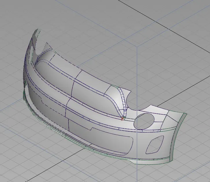
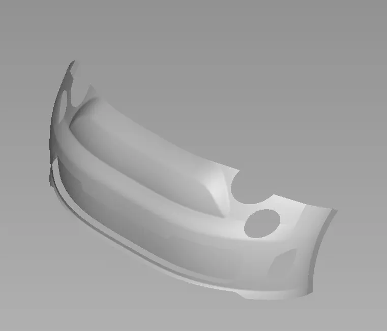
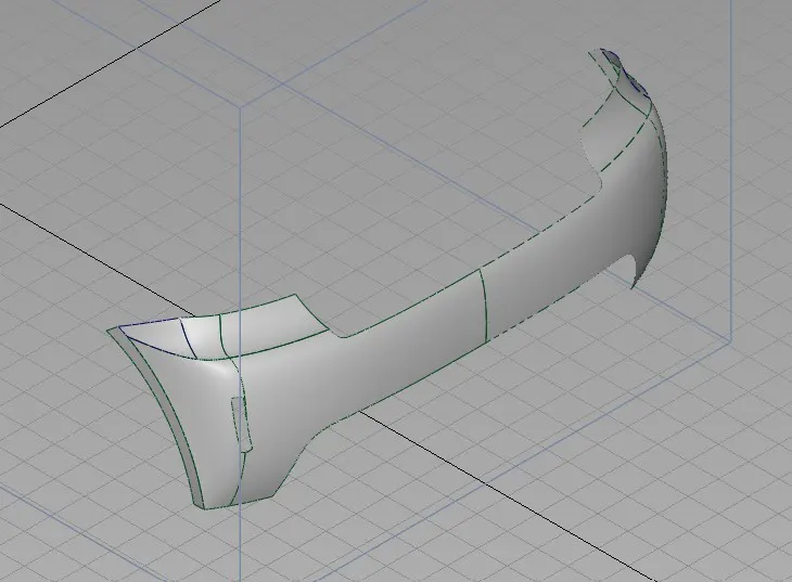
After creating all the curves create a symmetry/mirror. For that create another layer and assign all the curves in that layer. To create a symmetry go to the layers menu and in that go to symmetry. Symmetry will always be created in XY plane. If the model doesn’t lie on the same plane then the symmetry will be created but on different plane.
Front bumper-
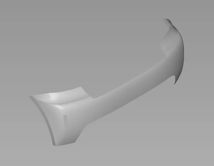
Rear bumper-
Interactive shading-
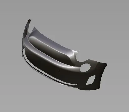
Interactive shading uses system’s graphic to draw surfaces. There are 2 form of interactive shading. Hardware shade and diagnostic shade either can be used to help visualize the model. However, each provides totally different practically.
Front bumper-
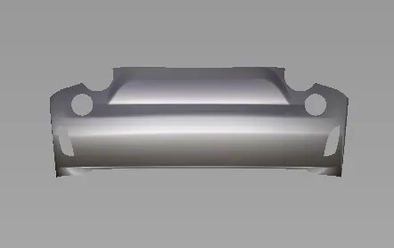
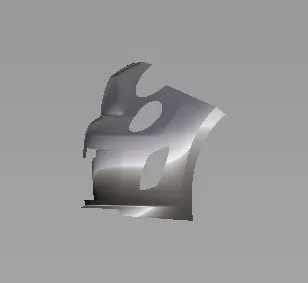
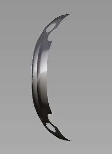
Rear bumper-
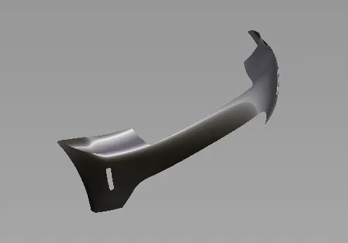
CONCLUSION
With the help of this project, we got to learn about surfacing the model and also about surface modelling with the help of Alias and got to learn about the surface tools.