Challenge 5
1. Explain the procedure of transverse analysis of deck slab of a metro viaduct.
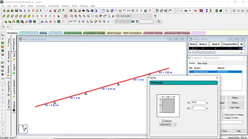
2. Explain the STAAD steps how the nodes & beams are created, and supports being assigned to those nodes for a slab in transverse modelling.
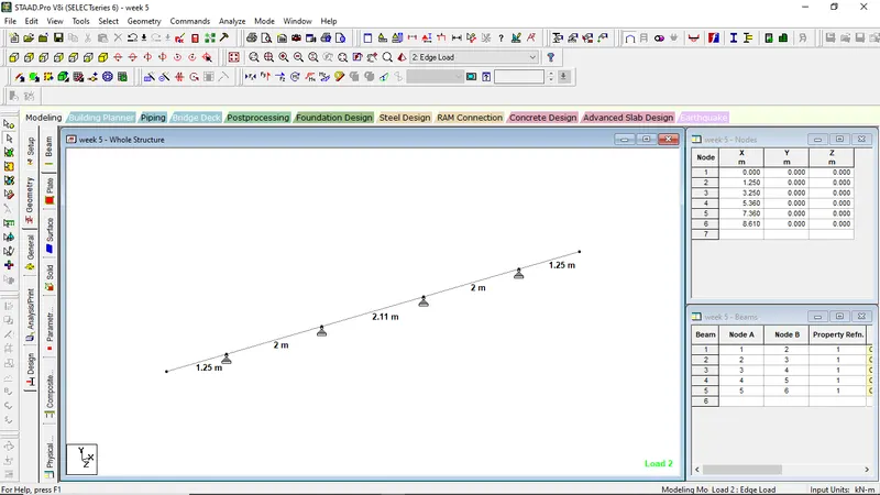
For creating of nodes
Go to the Geometry tool
Put the desired coordinate value such as (0,0,0), (1.250,0,0) , (3.250,0,0), (5.360,0,0), (7.360,0,0),(8.610,0,0)
For Creating Beams
Go to Beam Cursor
Select the first node point and connect it to the next node point
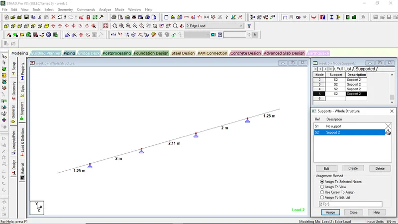
For Creating of support
Go to the Genera Tool
Click on support
Add pinned
and assign it to the required node
and assign it
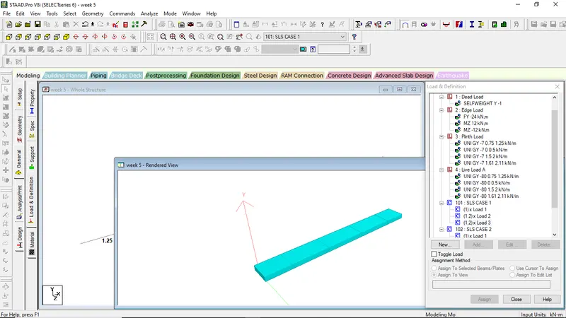
3. Explain how the loading values for SIDL, Dead lead, plinth load live load is calculated for assigning them in STAAD along with load combinations
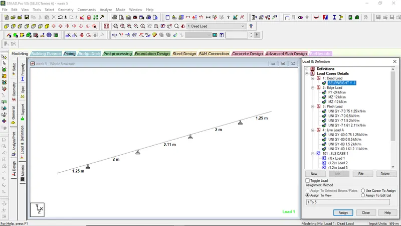
For Dead Load
Go to General Tool
Click on Loads and Defination
Click on Load Cases Details and select add
Click on Load type as Dead
and Name it as Dead Load and click add
In Dead select add
Add the selfweight value
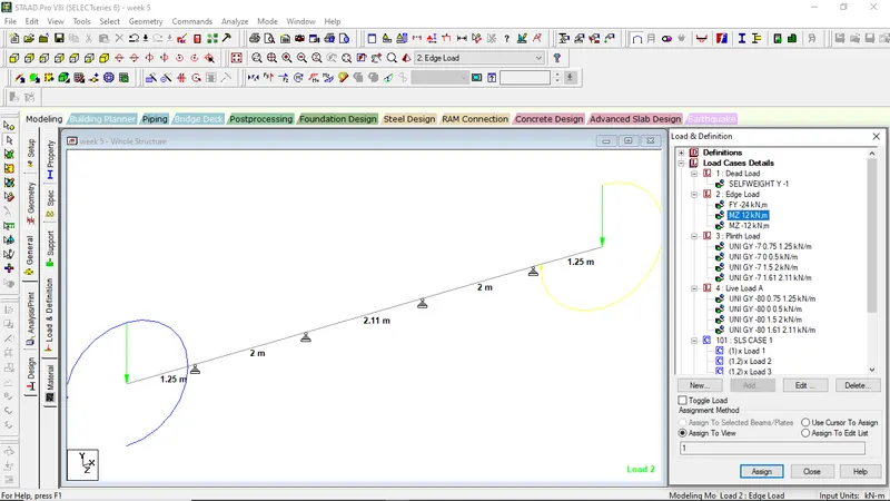
Similarly add the Edge Load, Plinth Load and Live load respectively
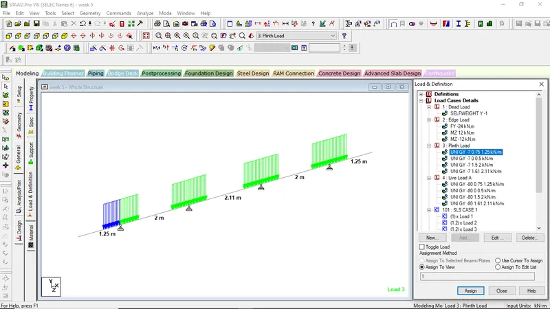
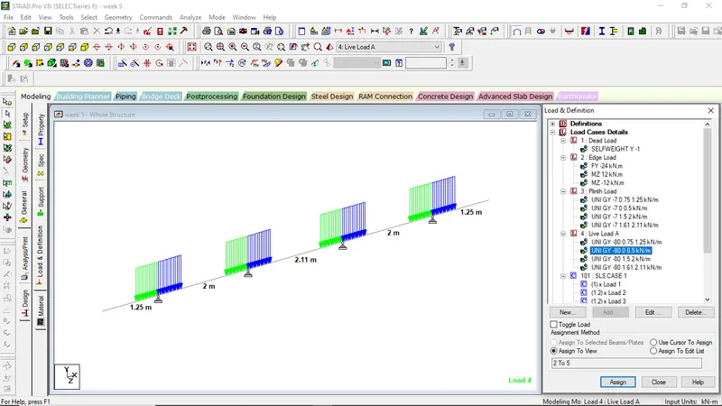
For Load Combination,
Go to Load Cases Details
Select on add
Go to define Combination
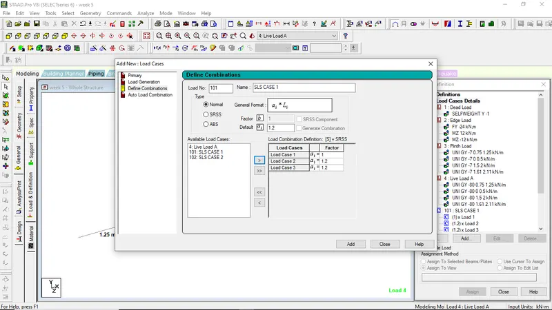
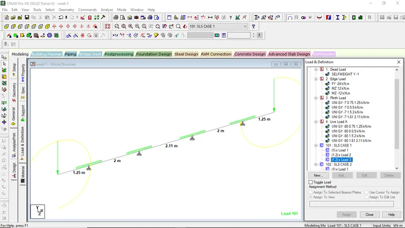
Create a slab in STAAD as per the video, assign the supports & loadings and extract the moments, perform the section checks, there by calculate the reinforcement for the slab.
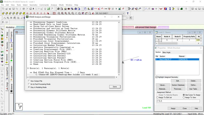
For Analyzing of Structure
For Post Processing Mode
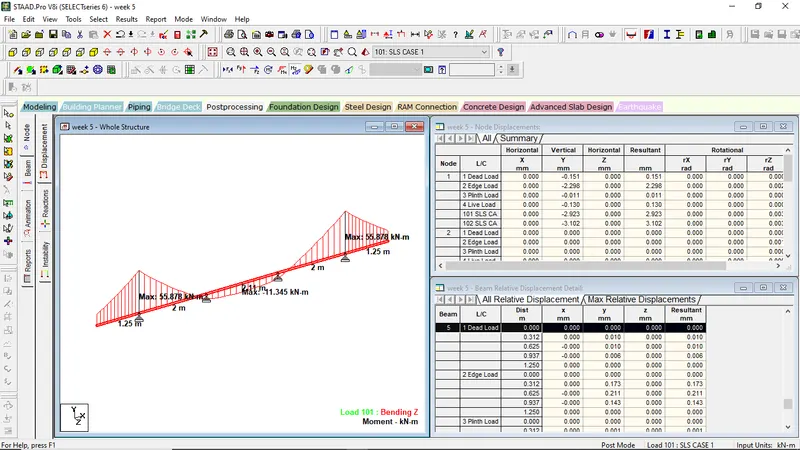
Maximum Bending Moment
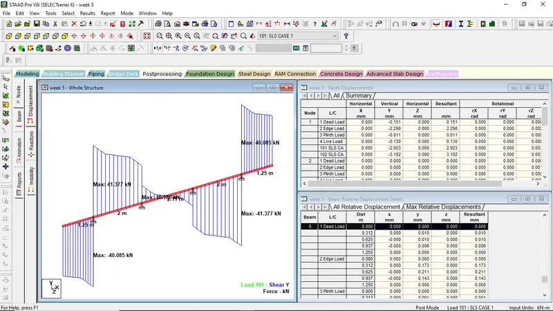
Maaximum Shear Force
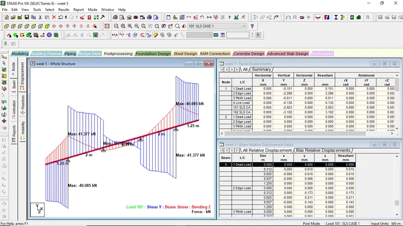
Explain the situations where mid diaphragms are provided in a viaduct.
In viaduct construction, mid diaphragms are structural components that are provided at regular intervals along the length of the viaduct. These diaphragms are horizontal or vertical bracing elements that connect the vertical piers or columns of the viaduct. They play an important role in providing stability, strength, and overall structural integrity to the viaduct. Here are some situations where mid diaphragms are commonly provided:
-
Lateral Load Resistance: Mid diaphragms help in resisting lateral loads that act on the viaduct structure. These loads can include wind forces, seismic forces, and traffic loads. By connecting the vertical piers, the diaphragms transfer the lateral loads between the piers, thus reducing the overall deflection and ensuring the stability of the viaduct during various loading conditions.
-
Structural Stiffness: Viaducts are subjected to various types of dynamic loads, such as vehicular traffic and wind-induced vibrations. The mid diaphragms enhance the stiffness of the viaduct structure, reducing its tendency to deform under these dynamic loads. They increase the torsional and flexural stiffness, thereby minimizing the sway and vibrations experienced by the viaduct.
-
Distribution of Live Load: Live loads, such as vehicular traffic, are not uniformly distributed along the length of the viaduct. Mid diaphragms help in distributing the live loads from the supported spans to the supporting piers. They transfer the loads to the adjacent piers, ensuring a more uniform distribution and reducing localized stresses on individual spans.
-
Construction Phasing: In the construction of long viaducts, mid diaphragms can be strategically placed to create construction segments. These segments allow for phased construction, where each segment is built independently, reducing the overall construction time and facilitating better quality control. The mid diaphragms provide temporary stability during the construction process until adjacent segments are connected.
-
Reducing Piers Spacing: In certain viaduct designs, mid diaphragms are used to reduce the spacing between piers. This can be advantageous in areas with difficult soil conditions or to minimize the overall footprint of the viaduct. By reducing the spacing between piers, the diaphragms help in transferring the loads to a larger number of supports, distributing the load more effectively.
Overall, mid diaphragms in viaducts contribute to the structural stability, stiffness, load distribution, and construction efficiency of the viaduct. Their presence ensures that the viaduct can safely withstand various loads and environmental conditions throughout its lifespan.
Where jacks can be placed for lifting the sections under the diaphragm. Also, what is the distance between the center of the girder to center of the jacks.
The placement of jacks for lifting sections under the diaphragm can vary depending on the specific design and construction requirements of the viaduct. However, a common approach is to position the jacks near the supports or piers of the viaduct. This allows for lifting and supporting the sections closest to the supports, which helps distribute the loads effectively.
Regarding the distance between the center of the girder to the center of the jacks, it depends on factors such as the design of the diaphragm, the dimensions of the girder, and the specific lifting method being used. Typically, this distance is determined based on engineering calculations to ensure the load is evenly distributed and the lifting operation is carried out safely.
To obtain accurate information about the distance between the center of the girder and the center of the jacks for a particular viaduct project, it is recommended to refer to the project's detailed design drawings, specifications, or consult with a qualified structural engineer or construction professional familiar with the specific viaduct design. They will be able to provide precise guidance based on the project requirements and constraints.