Challenge 4
1. What is a prestressed I girder? Why should a designer choose I girders when we are having double deck bridges and substantiate your answer with structural clearances?
A prestressed I-girder is a type of structural element commonly used in bridge construction and other civil engineering projects. It is designed to support heavy loads and spans by incorporating a combination of steel or concrete, and a pre-tensioning or post-tensioning system to increase its load-bearing capacity and reduce potential deflection or cracking.Here's how it works:
I-Girder Shape: The I-girder gets its name from its cross-sectional shape, which resembles the letter "I." This shape provides strength and stiffness, making it suitable for spanning long distances.
Material Selection: Prestressed I-girders can be made from various materials, but reinforced concrete and steel are the most common choices. The choice of material depends on factors like project specifications, budget, and local conditions.
Prestressing: The key feature of a prestressed I-girder is the use of prestressing. Prestressing involves applying a force (tension) to the structural element before it's subjected to the loads it will experience in service. This tension is usually achieved by using high-strength steel tendons (cables or bars) within the girder.
Pre-Tensioning: In pre-tensioning, the steel tendons are tensioned before the concrete is poured around them. Once the concrete cures and hardens, it adheres to the steel, and when the tendons are released, they pull the concrete into compression, making the entire structure stronger.
Post-Tensioning: In post-tensioning, the concrete is allowed to cure first, and then high-strength steel tendons are inserted into ducts or sleeves within the concrete and tensioned. The tension in the tendons compresses the concrete and enhances its load-carrying capacity.
When designing double-deck bridges, selecting the appropriate structural elements, such as girders, is crucial to ensure the bridge's safety, functionality, and cost-effectiveness. I-girders, also known as I-beams, are a common choice for bridge construction due to several advantages, but the selection should be based on specific project requirements and design considerations. Here are some reasons why designers might choose I-girders for double-deck bridges:
- Structural Efficiency
- Versatility
- Cost-Effectiveness
- Aesthetics
- Durability
- Ease of Construction
- Compatibility with Deck Systems
However, the choice of girders for a double-deck bridge will ultimately depend on various factors, including the specific project requirements, budget constraints, design aesthetics, local environmental conditions, and more. Engineers and designers need to evaluate these factors and conduct structural analysis to determine the most suitable girder type for the given project. In some cases, alternative girder types, such as box girders or truss girders, may be preferred based on the project's unique characteristics.
2. Explain the load flow behavior in a prestressed I girder for a metro viaduct?
The load flow behavior in a prestressed I-girder refers to how the internal forces and deformations are distributed throughout the girder when subjected to various loads. Prestressed I-girders are commonly used in bridge construction and other structural applications due to their ability to withstand significant loads while maintaining structural integrity. Understanding the load flow behavior is essential for structural engineers and designers to ensure that the girder can safely carry the applied loads. To analyze the load flow behavior in a prestressed I-girder, structural engineers use finite element analysis, structural software, and hand calculations. This analysis helps determine the internal forces and deformations throughout the girder, ensuring that it can safely carry the applied loads. It's also essential to consider factors such as creep, shrinkage, and long-term effects of prestressing when evaluating the behavior of the girder over its service life.
Proper design, construction, and maintenance are crucial to ensuring the long-term structural integrity of prestressed I-girders in bridge applications. Structural codes and standards provide guidelines for designing these girders to meet specific load and safety requirements.Here are some key aspects of load flow behavior in a prestressed I-girder:
Axial Load: Prestressed I-girders are designed to carry primarily axial loads, both compressive and tensile. The prestressing tendons (usually made of high-strength steel) provide an initial compressive force within the girder. This axial load helps the girder resist bending and shear forces.
Bending Moments: In real-world applications, I-girders are often subjected to bending moments due to various loads, such as the weight of the bridge deck, live loads (e.g., vehicles), and environmental conditions (e.g., wind and temperature changes). When bending moments are applied, the girder experiences bending stresses that result in curvatures.
Shear Forces: Shear forces can also be applied to the girder, especially at support points or due to the distribution of concentrated loads. The prestressed strands and the concrete's capacity to resist shear play a role in resisting these forces.
Torsion: Torsional effects, where the girder experiences twisting due to applied loads or eccentric loads, must be considered. Prestressed I-girders are typically more resistant to torsion compared to non-prestressed girders.
Deflection: Under the influence of various loads, the girder will experience deflection, which can impact the bridge's rideability. Engineers need to ensure that deflection remains within allowable limits.
Cracking and Stress Distribution: The prestressed concrete in the girder is designed to withstand tensile stresses. Cracking can occur at the locations of high tensile stresses, and the prestressing forces help control these cracks. The design should ensure that the cracks are controlled and do not compromise the structural integrity.
3. Explain codal provisions required for the design of I girders. Brief about the allowable stress with respect to the IRS CBC code.
Designing I-girders for structural applications, such as bridges, involves following specific codal provisions and standards to ensure the safety and functionality of the structure. The applicable codes and standards can vary by region and country. However, I can provide you with some widely recognized and used international codes and standards for the design of I-girders. It's essential to consult the specific codes and standards relevant to your location and project, as they may have local variations and updates. Here are some key codes and standards:
AASHTO (American Association of State Highway and Transportation Officials): In the United States, AASHTO provides a range of standards for the design and construction of highway bridges. For I-girders, you would typically refer to AASHTO LRFD (Load and Resistance Factor Design) Bridge Design Specifications.
ACI (American Concrete Institute): ACI offers standards related to concrete design and construction. ACI 318, Building Code Requirements for Structural Concrete, is an important reference for the design of concrete girders.
PCI (Precast/Prestressed Concrete Institute): For precast concrete girders, PCI publishes design and construction standards, including the PCI Design Handbook.
Eurocodes: In Europe, the Eurocodes are a set of standards for the design and construction of buildings and civil engineering works. Eurocode 2 (EN 1992) specifically deals with the design of concrete structures, including prestressed concrete girders.
Indian Standards (IS): In India, IS 456:2000 is the code for the design and construction of reinforced concrete structures. Additionally, IS 3370 Part 2 provides guidelines for the design of prestressed concrete structures.
CSA (Canadian Standards Association): CSA S6-14, Canadian Highway Bridge Design Code, is used for the design of highway bridges in Canada.
BS (British Standards): In the United Kingdom, BS 5400 is used for the design of highway bridges. Specific sections within BS 5400 deal with prestressed concrete design.
ISO (International Organization for Standardization): ISO provides standards for various aspects of construction and engineering, which can be referenced in different regions.
Local Building Codes: Many regions and municipalities have their own building codes and standards that supplement or modify the national or international codes. It's essential to be familiar with these local regulations.
When designing I-girders, you should consult the relevant codes and standards that apply to your project's location. These standards will provide guidelines on materials, loadings, design methods, and safety factors necessary to ensure the structural integrity and safety of the I-girder and the overall structure. Always work in compliance with the latest editions and amendments of these codes and standards to meet current best practices and ensure the safety of your construction project.
4. As per IRS CBC Table 11, SLS allowable stresses for RCC structure is 0.5 fck whereas for a PSC structure it is 0.4 fck. Explain the technical details of the aforesaid values. Also explain the behavior of stresses in a PSC girder with respect to the fck values
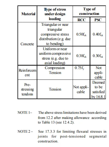
The behavior of stresses in a pre-stressed concrete (PSC) girder with respect to the characteristic compressive strength of concrete (fck) values is an important consideration in structural engineering and design. The characteristic compressive strength of concrete is a fundamental material property that impacts how the PSC girder will perform under various loads and conditions. Here's how the stress behavior in a PSC girder is influenced by different fck values:
Initial Strength and Load-Carrying Capacity: The characteristic compressive strength (fck) represents the nominal strength of the concrete mix. PSC girders are typically designed with a specified fck value that reflects the concrete's strength. Higher fck values result in a higher initial load-carrying capacity, which means the girder can support larger loads without failure.
Ultimate Strength: PSC girders are designed to withstand both service loads and ultimate loads. The fck value influences the ultimate strength of the concrete and, consequently, the girder. A higher fck value allows for a greater ultimate load-carrying capacity.
Prestressing Forces: The level of prestressing forces applied to the concrete also depends on the fck value. Higher fck values can lead to higher prestressing forces, resulting in increased tensile stresses within the concrete. This can help counteract the bending and shear forces experienced by the girder more effectively.
Ductility: The behavior of a PSC girder under load is also influenced by the ductility of the concrete. Concrete with higher fck values tends to be less ductile, meaning it may have less capacity to deform and redistribute loads before reaching failure. Designers must account for this in their design and detailing to ensure adequate safety and ductility.
Crack Control: The fck value affects the development and width of cracks in the concrete. Higher fck values can lead to narrower cracks for the same level of stress, which may affect durability and serviceability. Proper crack control measures, such as the use of additional reinforcement, are often needed.
Serviceability and Deflection: The fck value can also influence the serviceability of the PSC girder, including its deflection behavior under service loads. Higher fck values may lead to reduced deflections and can be beneficial for meeting serviceability criteria.
It's important to note that the choice of fck value should be based on the specific requirements of the project, including the expected loads, environmental conditions, and structural performance criteria. Designers typically select fck values that balance the need for adequate strength and performance while considering factors like cost, constructability, and long-term durability.
The behavior of stresses in a PSC girder is a complex interplay of various factors, including fck values, prestressing forces, and the structural design. A comprehensive structural analysis is required to ensure that the girder performs safely and reliably under different load conditions. This analysis should be conducted in accordance with applicable design codes and standards for PSC structures.
5. As IRS CBC, Table 10, what is design crack width and what are various exposure condition? Identify your city from the code and mention its exposure condition in India.
10.2.1 Cracking- Cracking of concrete shall not adversely affect the appearance or durability of the structure. The engineer should satisfy himself that any cracking will not be excessive, having regard to the requirements of the particular structure and the conditions of exposure. In the absence of special investigations, the following limit shall be adopted. (a) Reinforced concrete – Design crack widths, as calculated in accordance with 15.9.8.2, shall not exceed the values given in Table 10 under the loading given in 11.3.2
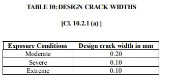
Note – Exposure conditions are as defined in 5.4.1. (b) Prestressed Concrete Structures and Elements – No tensile stresses are permitted and therefore, no cracks shall occur under the loading given in 11.3.2.
Chennai, located on the southeastern coast of India, experiences a tropical wet and dry climate. The exposure conditions for concrete structures in Chennai are influenced by both the environmental factors specific to the region and the general guidelines provided by Indian standards. The specific crack width exposure conditions in Chennai may vary depending on the location within the city and other site-specific factors.
In Chennai, as in other parts of India, the exposure conditions for crack width typically fall under one of the following categories:
Mild Exposure:
In areas of Chennai that are away from the coast and less affected by industrial pollution, a mild exposure condition may be considered. In such areas, the maximum allowable crack width is typically around 0.2 mm, as per IS 456: 2000.
Moderate Exposure:
Near the coastal areas or in urban and industrial parts of Chennai, where pollution and moisture levels are relatively higher, a moderate exposure condition may apply. In these cases, the maximum permissible crack width is generally around 0.3 mm, in accordance with the Indian standard.
Severe Exposure:
Certain specific locations in Chennai, particularly those closer to the coastline or exposed to aggressive elements like saltwater, may require structures to be designed for a severe exposure condition. The maximum crack width under severe exposure conditions is usually limited to 0.1 mm.
Very Severe Exposure:
In extremely aggressive environments near the coast, where high chloride and carbonation risks exist, a very severe exposure condition may be applicable. Under these conditions, the maximum allowable crack width is also typically 0.1 mm.
It's essential for engineers and designers in Chennai to assess the specific location, environmental conditions, and project requirements to determine the appropriate exposure class and select the corresponding maximum permissible crack width. Additionally, proper construction practices, choice of construction materials, and regular maintenance play crucial roles in managing and mitigating the risk of cracks in concrete structures in Chennai. Consulting local building codes and experts in the field can provide more precise information for your specific project.
6. What is a crossover in railways? Explain about the preference of I girder over U girders on viaduct, where crossovers are being constructed.
In railway systems, a "crossover" refers to a track arrangement that allows trains to switch from one track to another. It typically involves two or more railway tracks intersecting or crossing each other, allowing trains to move from one track to another for various operational purposes, such as changing lines or moving to a different platform.
Crossovers are essential components of railway infrastructure, as they enable the efficient and safe movement of trains on the rail network. They are used for various purposes, including:
Allowing trains to change tracks, either to pass slower-moving trains or to switch from one line to another.
Providing access to different platforms at railway stations.
Facilitating maintenance and repair work by allowing trains to move to different sections of the track.
Managing train traffic to avoid collisions or delays.
Regarding the preference for I girders over U girders on viaducts where crossovers are being constructed, this choice is typically made based on structural and design considerations. Both I girders and U girders are common structural components used in viaduct construction, but their suitability depends on several factors, including span length, load requirements, aesthetics, and local construction practices.
Here are some reasons for the preference of I girders in certain situations:
Strength and Stiffness: I girders, with their vertical web and top and bottom flanges, provide superior strength and stiffness compared to U girders. This added strength is important in viaducts, where the bridge structure must support the weight of trains and heavy loads.
Span Length: I girders are often preferred for longer span lengths, as they can provide better load-carrying capacity and structural stability.
Reduced Depth: I girders can be designed with a shallower depth while maintaining strength, which can be advantageous when clearance under the bridge is limited, such as in urban areas with overhead constraints.
Aesthetics: In some cases, the visual aesthetics of I girders are considered more appealing than U girders, which can be a factor in viaducts located in urban areas.
Local Standards and Expertise: The choice between I girders and U girders may also depend on local construction standards and the expertise of the construction industry in a specific region.
However, it's important to note that the choice of girder type should be made after a detailed structural analysis and engineering evaluation, taking into account factors such as span length, load requirements, site-specific conditions, and cost considerations. The final decision should align with safety, structural integrity, and cost-effectiveness.
7. What are SIDL considered for a viaduct design
In the context of viaduct design, "SIDL" typically stands for "Superimposed Dead Load." Superimposed Dead Load refers to the additional permanent loads that are placed on a structure beyond its own self-weight (which is considered a dead load). These loads include everything that the structure supports throughout its life, such as traffic loads, railings, utility lines, and other fixed or semi-permanent elements.
When designing a viaduct, engineers need to consider SIDL as a crucial factor to ensure the safety and structural integrity of the structure. Here are some common components or considerations related to SIDL in viaduct design:
Traffic Loads: Viaducts are designed to carry various forms of traffic, including cars, trucks, buses, and sometimes even trains. The weight and distribution of these vehicles are significant contributors to SIDL.
Railings and Barriers: The design must account for the weight and wind loads on any guardrails, parapets, or barriers installed on the viaduct.
Utilities: Viaducts may carry utility lines or conduits, such as water, gas, electricity, or telecommunications cables. The weight of these utilities and any associated equipment must be considered as part of the SIDL.
Snow and Ice Accumulation: Depending on the climate, the accumulation of snow and ice on the viaduct can contribute to the SIDL. This is particularly important for safety and maintenance considerations.
Future Expansion or Retrofitting: Engineers may also consider potential future changes or expansions that could increase the SIDL, such as the addition of lanes for increased traffic capacity.
Environmental Factors: Environmental conditions, such as earthquakes, wind, or other natural forces, can also be considered as part of SIDL.
Designing for SIDL requires a thorough structural analysis, which may include techniques like finite element analysis and load testing. Engineers aim to ensure that the viaduct can safely support all of these superimposed dead loads while maintaining its structural integrity and safety over its intended lifespan.
It's important to note that specific design standards and regulations may vary by location and the nature of the viaduct, so consulting with local engineering codes and standards is crucial for accurate and safe design. Additionally, advancements in materials and construction techniques continue to influence viaduct design practices.
9. Explain the procedure for calculating the CG of strands at mid-section of a girder, considering the following table and calculate the stresses at the bottom of the girder at the mid-section of the girder
|
Cable No |
No. of strands |
Eccentricity from bottom fiber(m) |
|
1 |
14 |
0.150 |
|
2 |
13 |
0.370 |
|
3 |
13 |
0.590 |
|
4 |
13 |
0.810 |
The procedure for calculating the center of gravity (CG) of strands at the mid-section of a girder typically involves determining the centroid of the strands. The center of gravity or centroid represents the point at which the entire weight of the strands is concentrated. This is an important calculation in structural engineering, especially when designing or analyzing structures like bridge girders.
Here's a step-by-step procedure for calculating the CG of strands at the mid-section of a girder:
Identify the Strands: Determine the number of strands and their individual characteristics, including their cross-sectional area (A) and location within the girder. The strands are typically made of steel cables or tendons used for reinforcing the concrete structure.
Define a Coordinate System: Establish a coordinate system for your analysis. For a typical girder, the positive x-axis runs along the length of the girder, and the positive y-axis is perpendicular to the girder. The origin of this coordinate system is usually at the centroid of the girder's cross-section.
Calculate the Area and Location of Each Strand: Calculate the area (A) and the x-coordinate (distance from the x-axis) of each strand. The x-coordinate is measured from the reference point (usually the centroid of the cross-section).
Calculate the Total Area: Sum up the cross-sectional areas of all the strands to find the total area (A_total).
Calculate the Moment of Each Strand: For each strand, calculate its moment about the x-axis (M_x) using the formula:
M_x = A * x
Where:
A is the cross-sectional area of the strand.
x is the distance of the strand from the reference point (centroid).Sum the Moments: Sum up the moments (M_x) of all the strands to find the total moment about the x-axis (M_total).
Calculate the CG Location: The location of the center of gravity (CG) is determined by dividing the total moment (M_total) by the total area (A_total):
CG_x = M_total / A_total
This CG_x represents the x-coordinate of the center of gravity of the strands at the mid-section of the girder.
Check the Sign Convention: Ensure that the sign convention for your coordinate system is consistent with the girder's actual layout. The CG_x should be positive if it's in the direction of the positive x-axis and negative if it's in the opposite direction.
The calculated CG_x represents the location of the center of gravity of the strands along the x-axis. This information is valuable for structural analysis and design, as it helps in understanding how loads are distributed and balanced within the girder. The same procedure can be applied to determine the CG in the y-axis if needed, depending on the specific analysis requirements.