Challenge 3
1. What are the sectional properties we need upfront for designing a metro viaduct? What is the supporting software for identifying the sectional properties and designing them?
1. Area
2. Perimeter
3. Bounding box
4. Centroid
5. Moment of inertia
Supporting software
1) Auto CAD
2) Shape builder
3) Staad Pro.
4) Midas
5) CSI bridge
2. Explain the detailed steps involved how elements are created in STAAD Pro and how are the inputs for sectional properties assigned?
Step 1 - Create Nodes by entering the corresponding X/Y/Z values in the Node table for Pier,Deck slab,Main girder and cross girders for I girder design.
Step 2 - After creating the nodes connect those nodes with add beam option.
Step 3 - Then Click specification tab and provide required support.
Step 4 - After that in create support dialog box add the required support with moment and forces assign to the four bottom corners of Piers.
Step 5 - After adding supports create required nodes in deck slab and I girder after that click Geometry tab and choose Add plates option
Step 6 - Then connect all 4 corners of the node with add plate option
Step 7 - Then in Properties tab add the required property like Tapered I beam for all main girder beams as given in question,Rectangular beam for Piers and cross beams of the deck slab,Plate thickness for all the plates in the geometry.
3. What are SLS combinations used for live loads, with respect to impact factor and how the moments for the section are derived?
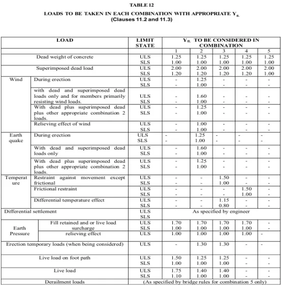
Calculating the impact factor and moment section by using this formula
I(Impact) = 1 + [0.15 + (8/(6 + L))] = 1.313
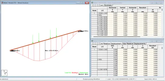
Moment(M) = (4183.35 + 1.2 x 1797.228 + 1.1 x 2969.161 x 1.313)kN-m = 10628.58 kN-m
4. What is prestressing in girders? What are advantages of Prestressed girders in a metro project.
A prestressed girder is a structural component commonly used in the construction of bridges, buildings, and other structures. It is a type of beam or girder that has been preloaded or subjected to internal stresses before it is put into service. This preloading is done to improve the structure.
Pre-Tensioning: In this method, the prestressing tendons (usually made of high-strength steel cables or wires) are tensioned before the concrete is poured. These tendons are typically placed in a mold or formwork and anchored at both ends. Once the concrete has sufficiently cured, the tendons are released, creating compressive forces within the girder. This compression counteracts the tensile forces that the girder will experience when it is loaded.
Post-Tensioning: In this method, the concrete is first poured without any prestressing tendons. After the concrete has partially cured, ducts or tubes are embedded within the concrete. High-strength steel tendons are then threaded through these ducts and tensioned using hydraulic jacks. The tendons are anchored at both ends, creating compressive forces in the concrete as they are tensioned. This method is often used for larger and more complex structures.
The benefits of using prestressed girders include:
Increased Load-Carrying Capacity: Prestressing increases the load-carrying capacity of the girder, allowing it to span longer distances and support heavier loads compared to non-prestressed girders.
Reduced Deflection: Prestressed girders exhibit reduced deflection (sagging) under load, which can result in flatter and more stable structures.
Improved Durability: Prestressed concrete can have enhanced resistance to cracking and fatigue, leading to longer-lasting structures.
Design Flexibility: Engineers can design prestressed girders to meet specific structural requirements, allowing for more efficient and economical designs.
Prestressed girders are commonly used in the construction of bridges, parking structures, commercial buildings, and other infrastructure projects where the need for long spans and high load-bearing capacity is critical.structural performance of the girder, especially its ability to resist bending and deflection under load.
5. Explain about prestressing losses? What are different type of prestressing losses and mention the significance of the prestressing losses?
Prestressing losses refer to the reduction in the initial prestressing force applied to a structure due to various factors and mechanisms. These losses are crucial to consider in the design and analysis of prestressed structures because they directly impact the structural behavior and performance. There are several types of prestressing losses:
Elastic Shortening: When the tendons are tensioned, the concrete undergoes elastic deformation and shortens in the direction of the applied force. This initial shortening is a temporary loss as it can be recovered when the tendon is released. However, it is a significant consideration in the design stage.
Creep: Creep is the time-dependent deformation of concrete under sustained load. As the concrete undergoes creep, it experiences additional deformation, leading to a loss in prestressing force over time.
Shrinkage: Concrete also experiences shrinkage over time as it dries and loses moisture. Shrinkage results in a reduction of prestressing force.
Relaxation: Relaxation occurs in the prestressing steel over time. Even after the tendons are stressed and anchored, the steel gradually loses stress due to various factors such as material properties and environmental conditions.
Friction: Friction between the tendon and the surrounding grout or duct material can lead to losses in prestressing force. Frictional losses occur both during the initial tensioning process and over time.
Anchorage Slip: The movement or slip of the tendon within the anchorage zone can cause losses in prestressing force. Proper anchorage design and installation are critical to minimize anchorage slip losses.
Curvature of Tendons: Tendons are often curved to fit within the profile of the structure. Curvature losses occur due to the curvature of tendons and result in reduced effective prestressing force.
Prestressing Force Measurement Errors: Errors in measuring the prestressing force during the tensioning process can lead to inaccuracies in the applied force, affecting the overall prestressing losses.
It's essential for engineers and designers to account for these prestressing losses in their calculations to ensure that the structure's performance meets the desired specifications over its service life. Various codes and standards provide guidelines for estimating and accounting for these losses in prestressed concrete design.
6. How a girder is being prestressed while fabrication? Explain the components/materials used during the prestressing?
Prestressing in the context of fabrication equipment and components typically refers to the application of mechanical forces or stresses to a material before it is put into service. This is done to improve the performance and structural integrity of the equipment or component. Prestressing is commonly used in the construction of bridges, buildings, and other large structures, but it can also be applied to certain fabrication equipment and components for specific purposes. Here are a few examples of prestressing in fabrication:
Prestressed Concrete Structures: In the fabrication of concrete structures such as beams, columns, and slabs, prestressing is often used. High-strength steel tendons or cables are placed inside the concrete forms before pouring the concrete. Once the concrete has cured to a certain strength, these tendons are tensioned, applying compressive forces to the concrete. This prestressing makes the concrete more resistant to tensile and bending stresses, increasing its load-bearing capacity.
Prestressed Bolts and Fasteners: Some fabrication equipment and components may use prestressed bolts and fasteners. These are bolts that are tensioned to a predetermined level before they are installed. This ensures a tight and secure connection that can withstand high loads and vibrations without loosening over time.
Prestressed Springs: Springs used in fabrication equipment, such as those in presses or machinery, may be prestressed to provide consistent and reliable performance. By preloading the spring with a specific amount of force, you can control its compression or extension characteristics within a defined range.
Prestressed Shafts and Bearings: In some cases, rotating components like shafts and bearings may be prestressed to reduce the risk of fatigue failure or to maintain precise alignment under load.
Prestressed Welded Joints: In welding, especially in critical structural applications, prestressing can be used to minimize residual stresses and prevent cracking in the weld. This can be achieved through techniques like stress relieving or post-weld heat treatment.
It's important to note that prestressing should be done carefully and according to engineering specifications to avoid over-stressing, which could weaken the material or component. Additionally, the choice of prestressing technique and level should be determined based on the specific requirements of the equipment or component and the materials used.Prestressing is a valuable technique in engineering to enhance the performance and durability of fabricated equipment and components, especially when they are subject to high loads, vibrations, or other demanding conditions.
7. How are stresses in the girder calculated with the resultant prestressing losses?
Calculating the stresses in a prestressed girder with resultant prestressing losses involves several steps and considerations. Prestressing losses occur over time due to various factors, such as creep, shrinkage, relaxation, and elastic deformation. These losses affect the initial stress in the prestressing tendons and consequently the stress distribution in the girder.Here's a simplified step-by-step process to calculate the stresses in a prestressed girder considering prestressing losses:
Determine the Initial Prestress: Start by determining the initial prestress in the tendons. This is typically calculated based on the design requirements and specifications.
Elastic Shortening: Calculate the initial elastic shortening due to the initial prestress. This is a straightforward calculation based on the material properties of the concrete and tendons.
Creep: Estimate the long-term deformation due to creep, which is the time-dependent deformation of concrete under sustained load. You'll need the creep coefficient and the age of loading.
Shrinkage: Account for the shrinkage of concrete over time, which leads to additional deformation. Shrinkage depends on factors such as concrete mix and environmental conditions.
Relaxation: Consider tendon relaxation, which is the gradual loss of prestress in the tendons over time. This loss depends on the type of tendon material and the relaxation characteristics.
Calculate the Final Prestress: Subtract the losses from the initial prestress to determine the final prestress in the tendons.
Determine the Stress Distribution: Analyze the girder's geometry, support conditions, and loading to determine the stress distribution. You'll need to consider the flexural and shear stresses in the girder.
Account for Prestressing Effects: The prestressing tendons provide an axial force that counteracts the external loads. The effect of this axial force on the stress distribution can be calculated using the principles of mechanics of materials.
Consider Other Loads: Consider the effects of live loads, dead loads, and any other relevant loads on the girder's stress distribution.
Analyze the Combined Effects: Combine the stresses due to prestressing, live loads, dead loads, and other loads to determine the total stresses at various points along the girder's length.
Check for Code Compliance: Ensure that the calculated stresses are within the allowable limits specified by the relevant design codes and standards.
Evaluate Safety and Serviceability: Assess whether the girder meets the safety and serviceability requirements, considering factors such as deflection, cracking, and durability.
Iterate as Needed: If the initial design doesn't meet the required criteria, make necessary adjustments to the prestressing force, girder dimensions, or reinforcement to achieve the desired performance.
Please note that this is a simplified overview of the process, and the actual calculations can be quite complex and may require the use of specialized software and engineering expertise. Additionally, the specific steps and considerations may vary based on the design requirements, materials used, and local building codes. It's crucial to work with a qualified structural engineer when designing and analyzing prestressed girders.
8.Explain the step wise procedure of transverse analysis of open web structure of U girders in STAAD pro along with how the vehicle parameters and loadings are fed in the STAAD software.
Following are the procedure
Step (1):- Opening The software and filling the model imformation
Step (2):- Creating U Girder model
Arranging the node in shape of U Grider
Connecting node by using add beam option
Copy node in X direction using the translational repeat option and assigning the plate using add plate option
Making Full U Girder model using translation repeat option.
Step (3):- Assinging the support
Specification -> Pinned suport -> Add -> select support 2 then select node -> Assign
Step (4):- Assgning the property to all plate
Property -> Thickness -> Add -> Select Plate -> assign 3D Model
Step (5):- Applying Loading on Model
Step (6):- Analyis of model
Step (7):- Result Extraction
9.How is the longitudinal analysis of open web structure of U girder performed, final design bending moments and axial stresses are extracted? Explain the software procedure for extracting the same.
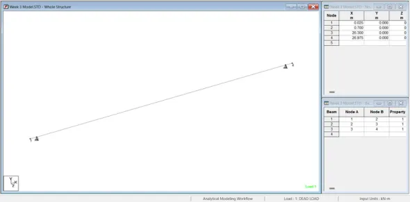
Step (1):- Creating Model & assigning Fix support.
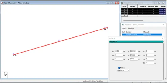
Step (2):- Assigning property
Step (3):- Applying Loads on model
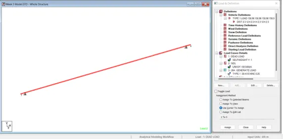
Step (4):- Analyis and Result extraction of model