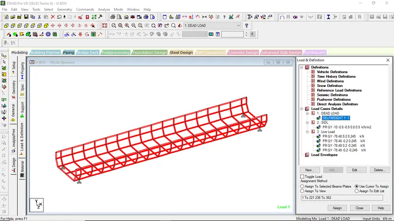
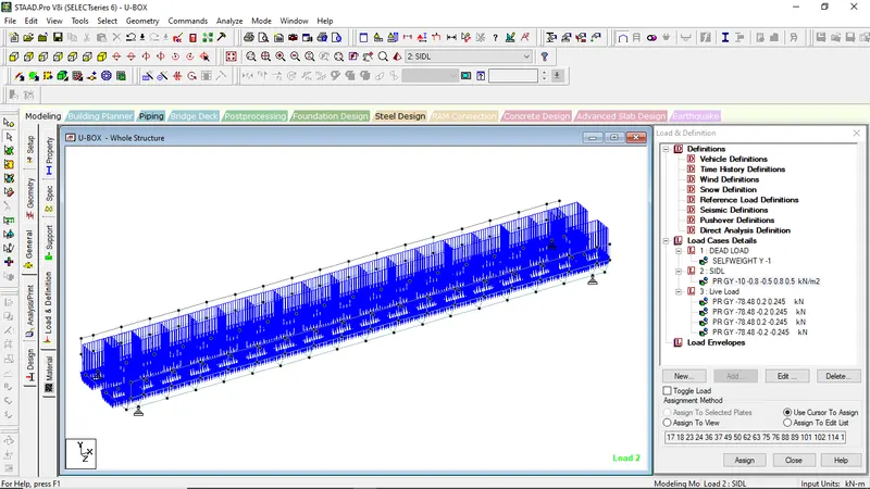
Challenge 3
1.What are the sectional properties we need upfront for designing a metro viaduct? What is the supporting software for identifying the sectional properties and designing them?
Ans:-
When designing a metro viaduct, there are several sectional properties that are crucial to consider. These properties include:
-
Cross-sectional Geometry: The dimensions and shape of the viaduct's cross-section, including the width, height, and any variations along the length of the structure.
-
Material Properties: The properties of the materials used for the viaduct, such as the elastic modulus, yield strength, and density. This information helps determine the structural behavior and load-carrying capacity of the viaduct.
-
Moment of Inertia: The moment of inertia is a measure of an object's resistance to changes in its rotational motion. For a viaduct, it is important to calculate the moment of inertia for different sections to assess their stiffness and resistance to bending.
-
Shear Area: Shear area refers to the portion of the cross-section that is effective in carrying shear forces. It is essential to determine the shear area to assess the viaduct's ability to withstand shear stresses.
-
Torsional Constants: Torsional constants are important for analyzing the torsional behavior of the viaduct. These constants include the torsional moment of inertia and the torsional section modulus.
-
Support Conditions: The type of supports used in the viaduct design, such as fixed supports or simply supported conditions, affects the distribution of forces and moments along the structure. The support conditions need to be identified and considered in the design process.
To identify and analyze these sectional properties, various software tools are available. Some popular software used for designing metro viaducts and determining sectional properties include:
-
AutoCAD: AutoCAD is a computer-aided design software that allows engineers to create 2D and 3D drawings of the viaduct. It helps in visualizing the cross-sectional geometry and extracting dimensions.
-
STAAD.Pro: STAAD.Pro is a structural analysis and design software widely used for analyzing complex structures like viaducts. It can calculate sectional properties, perform structural analysis, and generate design reports.
-
SAP2000: SAP2000 is another powerful structural analysis and design software that can assist in determining sectional properties and performing comprehensive analyses for metro viaducts.
-
ANSYS: ANSYS is a multiphysics simulation software that can be used for analyzing the structural behavior of viaducts. It provides advanced capabilities for determining sectional properties and performing complex simulations.
It's important to note that the choice of software may vary depending on the specific design requirements, engineering preferences, and company standards. Consulting with experienced structural engineers and considering project specifications will help in selecting the appropriate software and tools for metro viaduct design.
2.Explain the detailed steps involved how elements are created in STAAD Pro and how are the inputs for sectional properties assigned?
Ans:-
In STAAD.Pro, the process of creating elements and assigning inputs for sectional properties involves several steps. Here is a detailed explanation of the process:
-
Geometry Creation:
- Launch STAAD.Pro and create a new model or open an existing one.
- Define the coordinate system and units for the model.
- Use the available tools in STAAD.Pro to create the geometry of the viaduct. This typically involves specifying points, lines, arcs, and other geometric entities to represent the cross-sectional shape and the overall layout of the viaduct.
-
Element Creation:
- Once the geometry is created, you need to define elements to represent different parts of the viaduct.
- Select the appropriate element type for the viaduct sections. STAAD.Pro supports various element types such as beams, columns, plates, etc. For a viaduct, beam elements are commonly used.
- Place the elements in the model by specifying the start and end points or by picking points along the created geometry.
-
Sectional Properties Assignment:
- After creating the elements, you need to assign sectional properties to them. This step involves defining the material properties and cross-sectional dimensions for each element.
- Define the material properties such as elastic modulus, yield strength, and density. This information is typically provided by the material supplier or obtained from material testing.
- Specify the cross-sectional dimensions of the viaduct elements. This includes the width, height, thickness, or any other relevant dimensions based on the specific cross-section being used.
- You can assign predefined section properties available in the STAAD.Pro library or create custom sections by specifying the required geometric parameters.
- Assign the desired section properties to each element by associating the appropriate section to the corresponding elements.
-
Load Assignments and Analysis:
- Once the sectional properties are assigned, you can proceed to define the loadings and boundary conditions for the viaduct model.
- Apply the relevant loads such as dead loads, live loads, wind loads, etc., based on the design requirements and standards.
- Specify the support conditions at the points where the viaduct is connected to the piers or abutments.
- Run the structural analysis in STAAD.Pro to determine the structural response of the viaduct under the specified loads and boundary conditions.
-
Review and Iteration:
- After the analysis is complete, review the results and assess the structural performance of the viaduct.
- If necessary, make adjustments to the sectional properties, loadings, or support conditions based on the analysis results and engineering judgment.
- Iterate the process until a satisfactory design is achieved, considering factors such as safety, serviceability, and economy.
It's important to note that the specific steps and terminology may vary slightly depending on the version of STAAD.Pro and the project requirements. It is recommended to refer to the software's documentation or consult experienced structural engineers familiar with STAAD.Pro for guidance throughout the modeling and analysis process.
3.What are SLS combinations used for live loads, with respect to impact factor and how the moments for the section are derived?
Ans:-
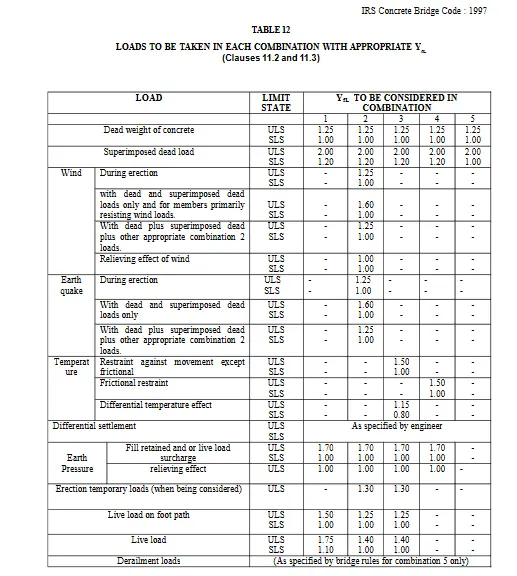
In structural engineering, SLS (Serviceability Limit State) combinations are used to assess the performance of a structure under various service loads. These combinations consider different load factors and reduction factors to determine the design moments for the section. When considering live loads, an impact factor may be applied to account for dynamic effects. The moments for the section are derived based on these factors and combinations.
-
Live Load Impact Factor:
- Live loads, such as vehicle loads on a viaduct, are typically considered dynamic loads due to their moving nature and potential for dynamic effects.
- An impact factor is used to account for the dynamic amplification of the live load. It represents the additional effect caused by the dynamic nature of the load and is applied to the static live load.
- The impact factor is typically expressed as a multiplication factor, which is applied to the live load to obtain the dynamically amplified load for design purposes.
- The specific impact factor to be used depends on the design code or standard being followed. Different codes may provide different guidance on impact factors for different types of structures and loading conditions.
-
SLS Combinations for Live Loads:
- SLS combinations are used to consider the effects of various loads acting simultaneously on the structure.
- In the case of live loads, SLS combinations typically include the live load in combination with other relevant loads, such as dead loads, wind loads, or temperature effects.
- The specific SLS combinations to be used depend on the design code or standard being followed. These combinations are typically specified in the code along with the load factors and reduction factors to be applied to each load component.
-
Deriving Moments for the Section:
- Once the load combinations are defined, the moments for the section can be derived by performing structural analysis.
- The load combinations, including the live load with the impact factor applied, are used as input for the analysis.
- The analysis may involve methods such as finite element analysis, frame analysis, or other appropriate techniques to determine the internal forces and moments in the structure.
- The moments at various sections along the viaduct are obtained as a result of the analysis, representing the bending moments experienced by the structure under the applied loads.
It's important to note that the specific impact factor and SLS combinations for live loads, as well as the methods for deriving moments, may vary depending on the design code or standard being followed. It is crucial to refer to the specific design code or consult with experienced structural engineers familiar with the applicable standards for accurate and appropriate application.
4.What is prestressing in girders? What are advantages of Prestressed girders in a metro project.
Ans:-
Prestressing in girders refers to a technique used in structural engineering where a compressive force is intentionally applied to a concrete member before it is subjected to external loads. This compressive force, known as prestress, is typically achieved by tensioning high-strength steel tendons or cables and anchoring them to the concrete.
Advantages of Prestressed Girders in a Metro Project:
-
Increased Load-Carrying Capacity: Prestressed girders can significantly enhance the load-carrying capacity of a metro viaduct. By applying a compressive force to the concrete, prestressing counteracts the tensile stresses induced by external loads, thereby increasing the capacity of the girders to resist bending and shear forces. This allows for the design of lighter and more slender girders while maintaining structural integrity.
-
Longer Spans and Fewer Supports: The increased load-carrying capacity of prestressed girders allows for longer spans between supports. This results in reduced the number of piers or supports required along the viaduct alignment. Fewer supports not only reduce construction costs but also minimize obstructions to traffic, pedestrians, and utilities underneath the viaduct, improving overall project aesthetics and efficiency.
-
Enhanced Durability: The application of prestress in girders helps to minimize cracking and deformation under service loads. By counteracting the tensile stresses, prestressing improves the durability of the girders and increases their resistance to various external factors, such as shrinkage, temperature changes, and long-term creep. This leads to a longer service life for the viaduct and reduces the need for maintenance and repair.
-
Improved Structural Performance: Prestressed girders exhibit better deflection control and improved resistance to vibration compared to non-prestressed girders. The prestress force reduces the deflection and deformation of the girders, resulting in improved structural performance, increased ride comfort for passengers, and better dynamic behavior under live loads and seismic events.
-
Construction Efficiency: Prestressed girders offer advantages in terms of construction efficiency. The prefabrication of prestressed girders in controlled factory conditions allows for accurate production and quality control. These girders can be transported to the construction site and quickly installed, reducing on-site construction time and disruption. This efficiency is particularly beneficial for metro projects, where timely completion is crucial to minimize disruptions to urban transportation systems.
Overall, the use of prestressed girders in metro projects provides numerous benefits, including increased load-carrying capacity, longer spans, improved durability, enhanced structural performance, and construction efficiency. These advantages contribute to cost savings, reduced maintenance needs, and improved safety and reliability of the metro viaduct.
5.Explain about prestressing losses? What are different type of prestressing losses and mention the significance of the prestressing losses?
Ans:-
Prestressing losses refer to the reduction or dissipation of the initial prestress force applied to a prestressed concrete member over time. These losses occur due to various factors and are important to consider in the design and analysis of prestressed structures. Understanding and accounting for prestressing losses is crucial to ensure the long-term performance and structural integrity of the members.
Different Types of Prestressing Losses:
-
Elastic Shortening: When prestressing tendons are tensioned, the concrete member experiences immediate shortening due to the elastic response of the materials. This initial shortening, known as elastic shortening or immediate deformation, is an instant loss of prestress that occurs during the stressing operation. It is caused by the compression of the concrete and the elongation of the prestressing tendons. Elastic shortening is typically calculated based on the material properties and the stress-strain relationships.
-
Creep: Creep refers to the time-dependent deformation of concrete under sustained load. When prestressed concrete members are subjected to constant or long-term loads, the concrete gradually undergoes creep, resulting in additional losses of prestress. Creep is influenced by factors such as the characteristics of the concrete, humidity, temperature, and stress levels. It is typically accounted for by using creep coefficients and long-term relaxation values provided by design codes or empirical models.
-
Shrinkage: Concrete experiences shrinkage as it cures and loses moisture. Shrinkage causes the concrete to contract, resulting in a reduction of prestress. Shrinkage losses are influenced by factors such as the mix design, curing conditions, and environmental factors. Design codes usually provide shrinkage coefficients or empirical equations to estimate the amount of shrinkage-induced prestress loss.
-
Relaxation: Relaxation refers to the gradual loss of prestress in the tendons over time due to factors such as steel relaxation, friction, and anchorage movement. Steel relaxation is the reduction of stress in the prestressing tendons due to the steel's viscoelastic behavior. Friction losses occur due to the resistance encountered by the tendons as they pass through ducts or anchorages. Anchorage movement, if not properly accounted for, can also contribute to relaxation losses.
Significance of Prestressing Losses:
-
Safety and Serviceability: Accurate estimation and consideration of prestressing losses are essential for ensuring the safety and serviceability of prestressed concrete members. By accounting for the losses, the design can ensure that the resulting residual prestress is sufficient to withstand the anticipated loads and maintain the desired structural behavior over the structure's design life.
-
Deflection Control: Prestressing losses directly affect the deflection and deformation of prestressed concrete members. Accurate estimation of losses helps to determine the final deflection under service loads, allowing for proper control and compliance with deflection limits. Excessive deflections can affect the serviceability and performance of the structure, leading to discomfort for occupants and potential damage to finishes and non-structural elements.
-
Long-Term Performance: Understanding prestressing losses is crucial for predicting the long-term behavior and performance of prestressed concrete structures. By accounting for losses, engineers can evaluate the durability, fatigue resistance, and stability of the members over time, ensuring that the structure will meet its performance requirements throughout its design life.
-
Design Optimization: Considering prestressing losses allows for more accurate design optimization. By understanding the magnitude and nature of the losses, engineers can optimize the initial prestress force, tendon layout, and member dimensions to achieve the desired structural performance while accounting for the anticipated losses.
6.How a girder is being prestressed while fabrication? Explain the components/materials used during the prestressing?
Ans:-
During the fabrication of a prestressed girder, several components and materials are used to achieve prestressing. The general process involves the following steps:
-
Preparing the Concrete Formwork:
- The formwork is prepared to create the desired shape and dimensions of the girder. This can involve constructing a mold or using precast formwork.
-
Placing Reinforcement:
- Steel reinforcement, such as reinforcing bars (rebar), is placed in the formwork according to the design requirements. The reinforcement provides additional strength to the girder and helps control cracking.
-
Placing Ducts:
- Ducts or conduits, typically made of high-density polyethylene (HDPE) or galvanized metal, are placed within the formwork. These ducts serve as pathways for the prestressing tendons.
-
Placing Prestressing Tendons:
- High-strength steel tendons, typically in the form of strands or wires, are placed inside the ducts. These tendons will provide the prestressing force to the girder.
- The tendons are tensioned by applying a high force at one end and anchoring them securely at the other end. This tensioning is usually done using hydraulic jacks.
-
Grouting:
- Once the tendons are tensioned, grout is injected into the ducts under pressure. The grout, usually composed of cementitious material mixed with water, fills the space around the tendons and provides protection against corrosion and bonding between the tendons and the concrete.
-
Curing:
- After the grouting process, the concrete girder is left to cure and gain strength. Proper curing ensures the development of the desired strength and durability properties.
The materials used during the prestressing process include:
-
Concrete:
- Concrete is the primary material used for the girder. It provides strength, durability, and the required shape of the structure. High-strength concrete is often used for prestressed girders to withstand the applied forces.
-
Reinforcement:
- Steel reinforcement, in the form of rebar, is placed in the girder to enhance its strength and control cracking. Reinforcement is typically located in areas of the girder that are not prestressed.
-
Prestressing Tendons:
- Prestressing tendons are made of high-strength steel and are the key components in prestressed girders. These tendons can be in the form of strands or wires, and they provide the compressive force to counteract the tensile stresses in the girder.
-
Ducts:
- Ducts are used to house the prestressing tendons and protect them during the fabrication process and throughout the life of the girder. HDPE or galvanized metal ducts are commonly used for this purpose.
-
Grout:
- Grout is a cementitious material mixed with water and other additives. It is injected into the ducts after tensioning the tendons to ensure bonding, corrosion protection, and load transfer between the tendons and the surrounding concrete.
The combination of these components and materials, along with proper fabrication techniques, allows for the creation of prestressed girders with enhanced strength, load-carrying capacity, and durability.
9.How is the longitudinal analysis of open web structure of U girder performed, final design bending moments and axial stresses are extracted? Explain the software procedure for extracting the same.
Ans:-
STEP-1
Model the U-Girder in Single line Diagram
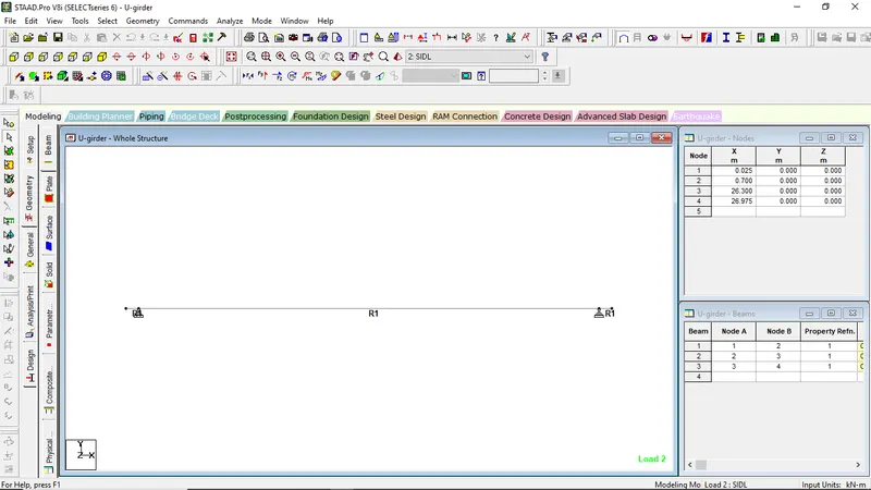
STEP-2
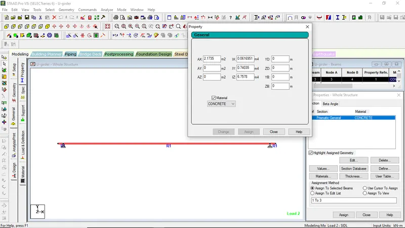
Assign the material Property
Go to general
Material Property
Go to Define
Go to general
Put the calculated values
STEP-3
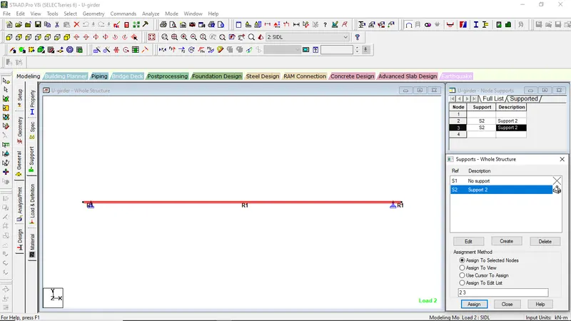
Support Condition
Go to general
Click on Support
Select Pinned Support
STEP-4
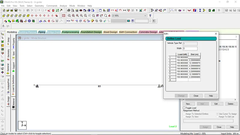
Application of Loadings:-
Go to General
Select Load and Definations
Go to the Defination
Select Vehicle Definatons
Put the calculated values
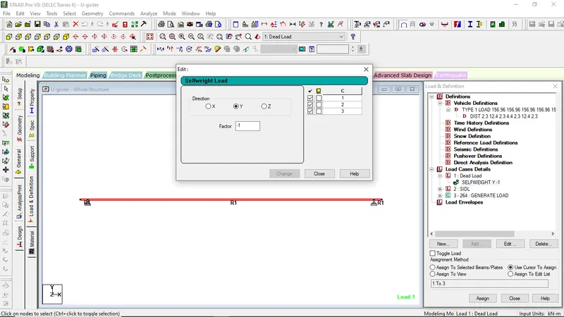
For Dead Load
Select Load cases details
Select loading type as Dead
Click on Dead
Add selfweight
For SIDL
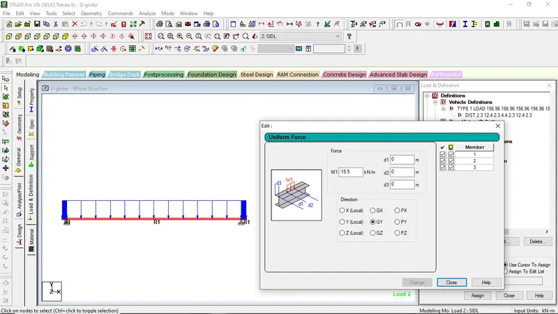
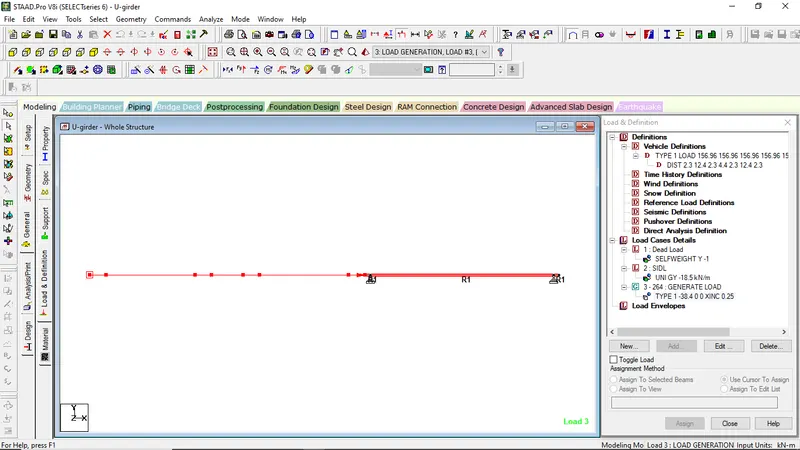
For Vehicle Load
Select Load Generation on Load Case Details
No of loads to be generated=262
STEP-5
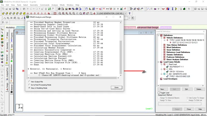
ANALYSIS OF MODEL
Go to Analysis/print
Select on no print
Go to analyze menu
click on run analysis
Go to Post Processing mode:-
Carry out the all the SF AND BM
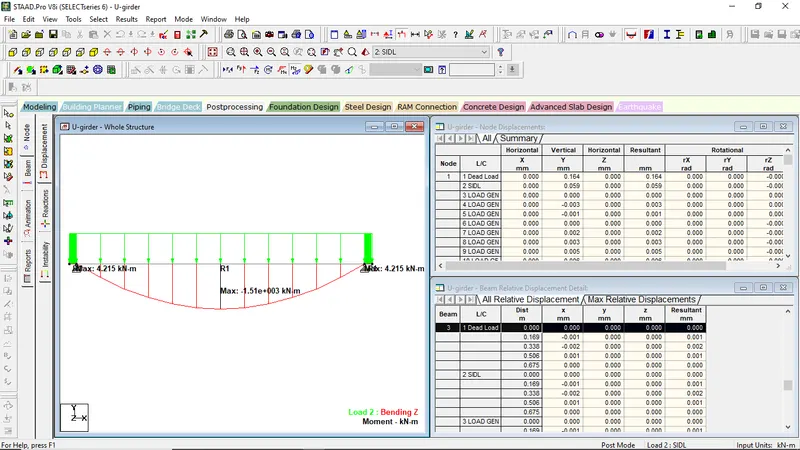
Maximum Bending moment on SIDL
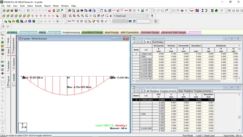
8.Explain the step wise procedure of transverse analysis of open web structure of U girders in STAAD pro along with how the vehicle parameters and loadings are fed in the STAAD software.
STEP-1
Modelling of U-Girder as per given question
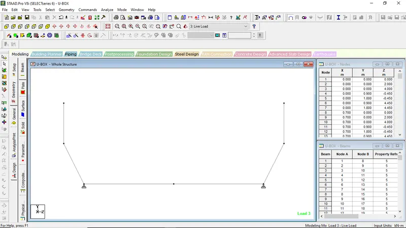
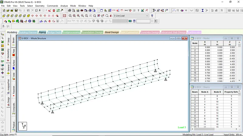
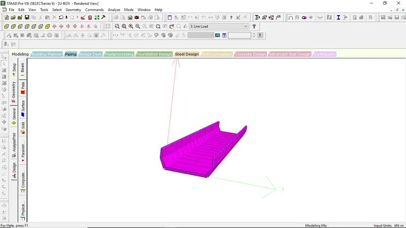
STEP-2
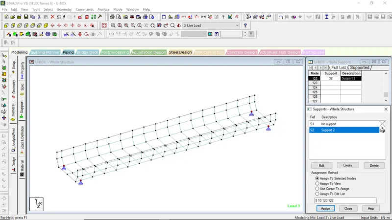
Applying Supports to the girder
STEP-3
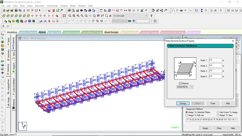
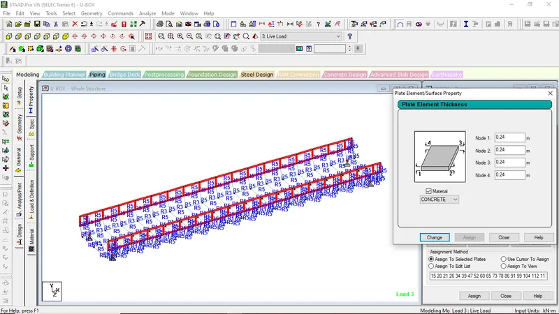
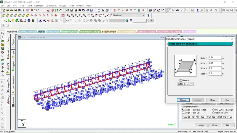
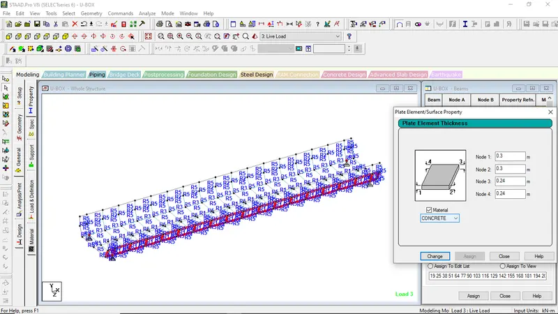
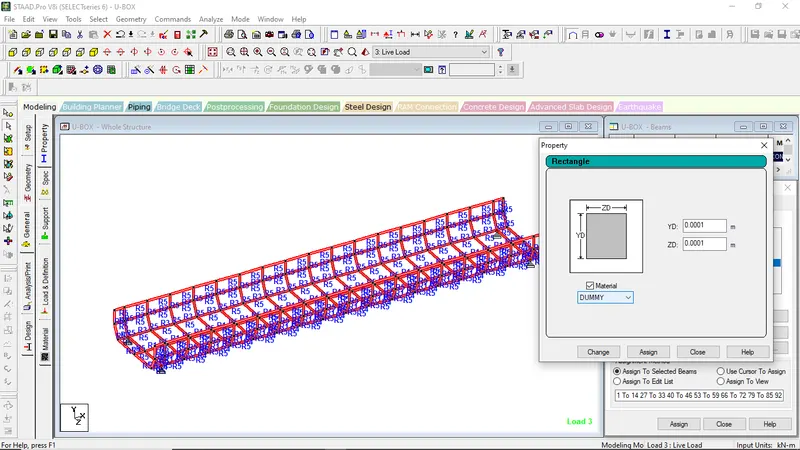
Providing Material Property to the girder:-
STEP-4
Application of Loads