Challenge 2- Comparing the performance of three types of beams under bending load.
Aim:
- To compare the performance of three types of beams under a bending load.
- To create the design of the beam by the given data.
Introduction:
- Simple bending or pure bending A beam or a part of it is said to be in a state of pure bending when it is bent under the action of a uniform or constant bending moment without any shear force.
- Alternatively, a portion of the beam is said to be in a state of simple bending or pure bending, when the shear force on that portion is zero.
- In that case, there is no possibility of shear stress in the beam.
- When a beam is loaded with external loads all the sections will experience a bending moment.
- The bending moment at a section tends to bend or deflect the beam and the internal stresses resist its bending.
- The resistance, offered by the internal stresses to the bending, is called bending stress.
- Bending stresses are the internal resistance to external force which causes bending of a member.
- It is denoted by σ. Its unit will be N / mm².
- In the bending process, the inner surfaces of the beam contract, and the outer surfaces expand.
- Therefore, there must be a surface somewhere in the middle of the beam, whose length does not change, this surface is called the "neutral layer".
- There is no stress on this surface.
Some practical applications of bending stresses are as follows:
- Moment carrying capacity of a section.
- Evaluation of excessive normal stress due to bending.
- Design of beam for bending.
- Evaluation of the load-carrying capacity of the beam.
- Design as determined by the type of load
Assumptions for Theory of Simple Bending
- The material of the beam is perfectly homogeneous and isotropic.
- The beam material is stressed within its elastic limit and thus, obeys Hooke's law.
- The transverse sections, which were plane before bending, remain plane after bending also. Each layer of the beam is free to expand or contract, independently, of the layer above or below it.
- The value of E (Young's modulus of elasticity) is the same in tension and compression.
- The beam is in equilibrium i.e., there is no resultant pull or push in the beam section.
The basic steps for doing this project are as follows:
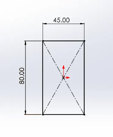
- First make a sketch of the beam using the sketch tool with the proper dimensions.
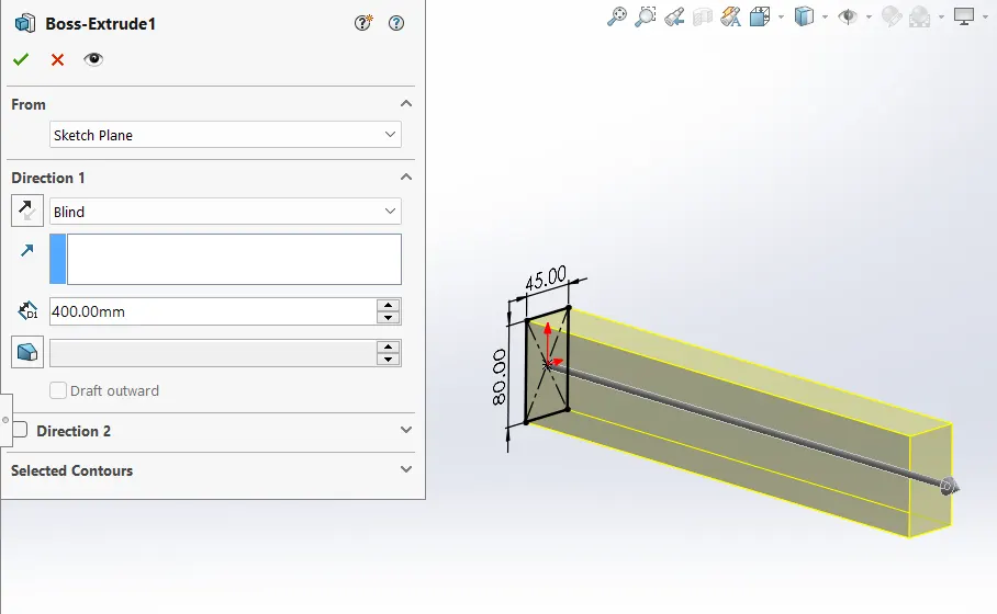
- Extrude the sketch up to 400mm using extrude boss/base. Now beam is ready for simulation.
BEAM_1
BEAM_2:
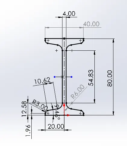
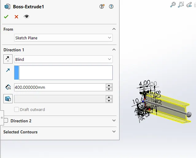
BEAM_3:
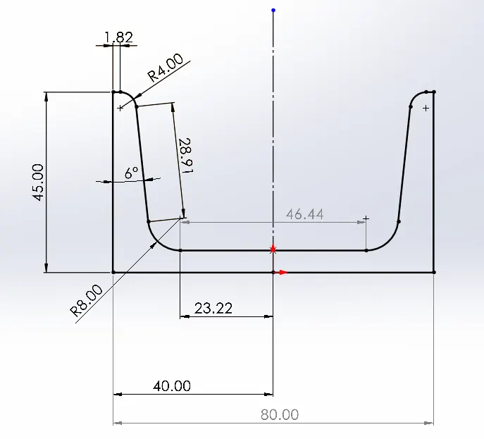
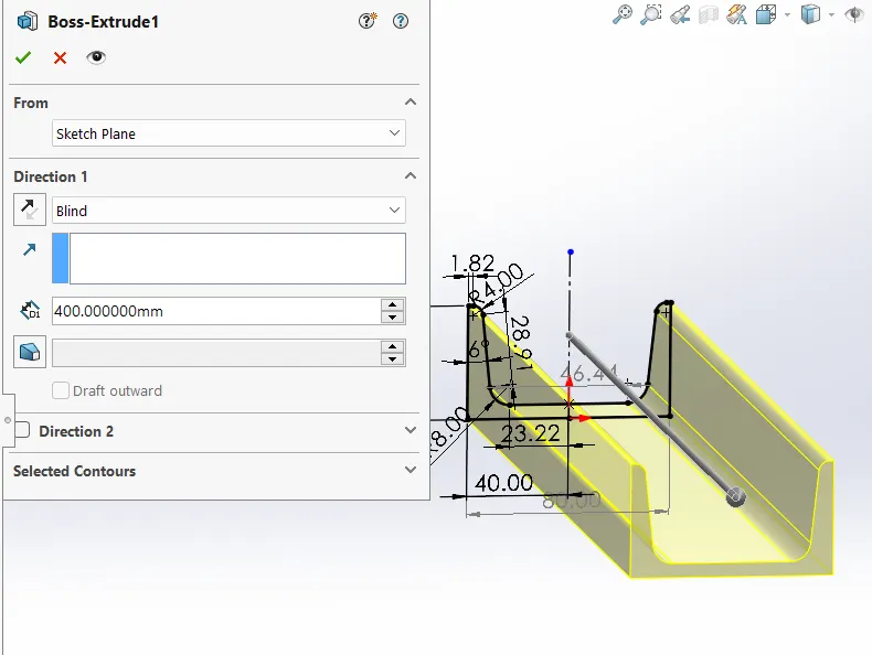
Now use the simulation command and set all required data are as follows:
- After designing click on the stimulation and select the static.
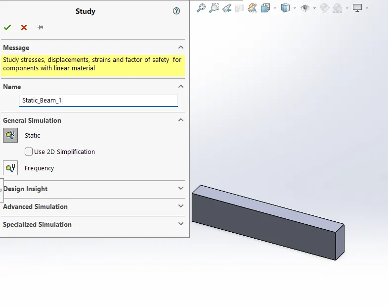
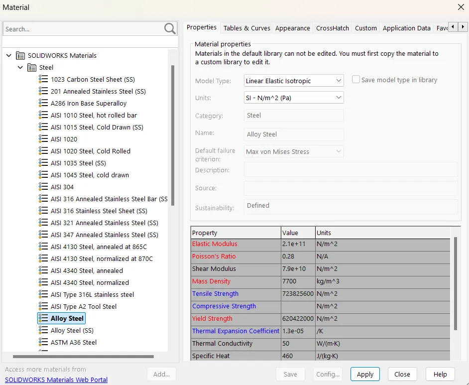
- Add materials here "alloy steel" is taken.
- Add fixture < fixed geometry< select end face and say ok.
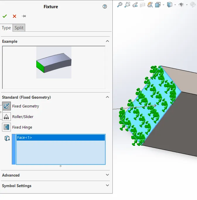
- Create mesh. Any type of mesh you can apply but fine mesh gives enough accuracy.
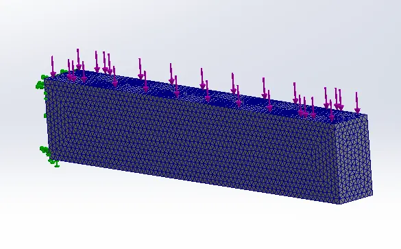
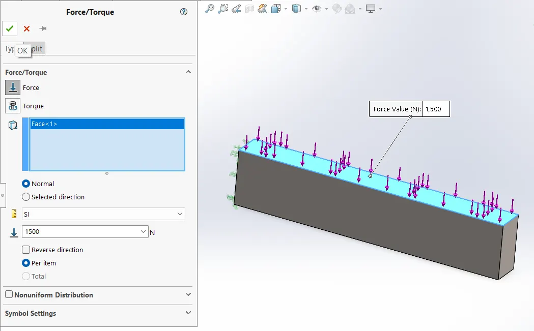
- Apply force on the face of 1500N.
- Now time to run the study and get the result.
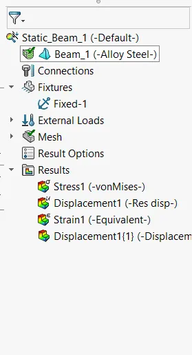
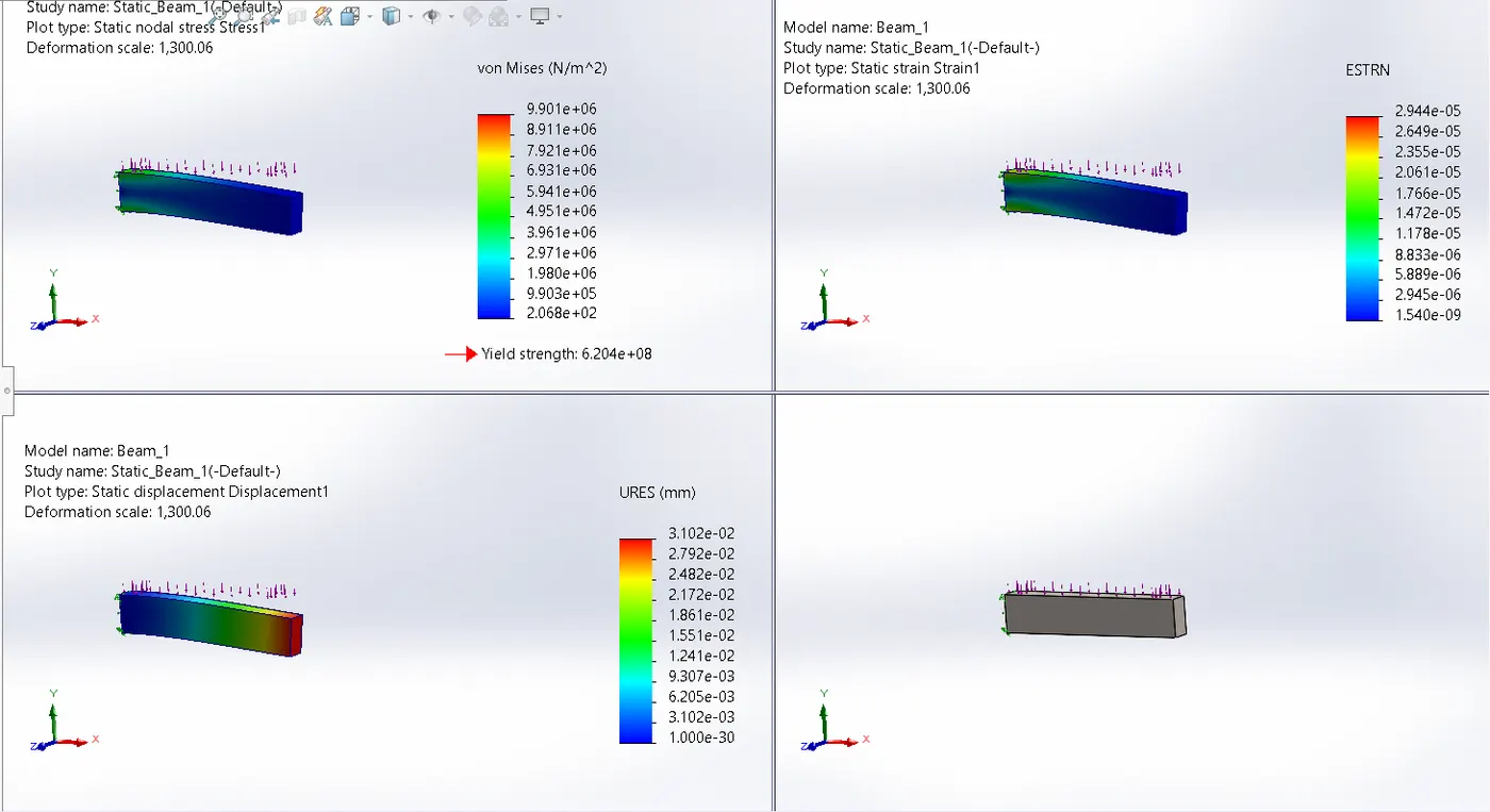
- Similarly remaining two beams are simulated and get results.
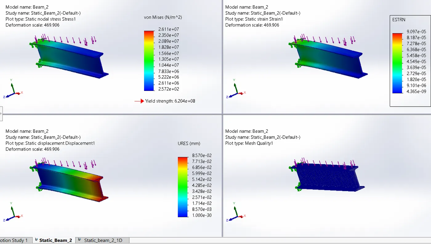
Beam_2:
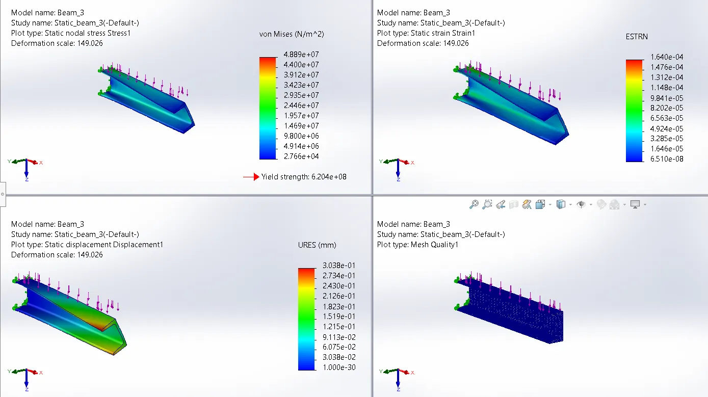
Beam_3:
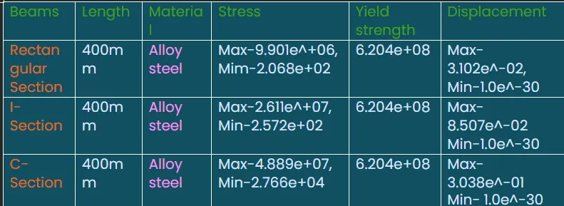
Observation:
Result:
- Maximum stress in all beams is lower than the yield strength of all beams is accepted in view of stress concentration, but maximum displacement is least in c section beam and maximum in rectangular beam.
Animation:
Stress_Beam_1:
Stress_Beam_2:
Stress_beam_3:
Displacement_Beam_1:
Displacement_Beam_2:
Displacement_Beam_3: