Challenge 2- Comparing the performance of three types of beams under bending load.
Challenge 2- Comparing the performance of three types of beams under bending load
AIM
Comparing the performance of three types of beams under bending load in Solidworks
INTRODUCTION
inite element analysis (FEA) is the use of calculations, models and simulations to predict and understand how an object might behave under various physical conditions. Engineers use FEA to find vulnerabilities in their design prototypes.
FEA uses the finite element method (FEM), a numerical technique that cuts the structure of an object into several pieces, or elements, and then reconnects the elements at points called nodes. The FEM creates a set of algebraic equations which engineers, developers and other designers can use to perform finite element analysis.
Frequently, the physical experiences of a product -- such as its structural or fluid behavior and thermal transport -- are described using partial differential equations (PDEs). Finite element analysis emerged as a way for computers to solve both linear and nonlinear PDEs. However, it is important to note that FEA only provides an approximate solution; it is a numerical approach to finding the real results of partial differential equations.
Using finite element analysis can reduce the number of physical prototype created and experiments performed while also optimizing all components during the design phase. Finite element analysis software emerged in the 1970s with programs such as Abaqus, Adina and Ansys. Now, it is common to find virtual testing and design optimization integrated into the product development cycle to improve the product quality and reduce the time it takes to enter the market.
Types of FEA tests
Various different types of tests are used during finite element analysis, such as:
- Structural static analysis. This type of FEA analyzes a scaled model based on proportions. The test maintains that any structure that is sound on a small scale will be able to handle the same interactions with the full-scale structure and produce the same results.
- Thermal engineering analysis. This test explores variations in temperature and how it affects the design structure.
- Modal analysis. Every object vibrates at a frequency, so it is important to use modal analysis to test how disruptive external vibrations affect the product's structure. This form of finite element analysis also allows users to adjust for vibrations throughout the design stage, thus creating a strong final product.
- Engineering seismic calculations. This test helps developers understand the product's performance when dealing with various ground frequencies and vibrations, ensuring a sturdy location for the final structure.
Finite element analysis is used to solve numerical differential equations of complex parameters used in engineering and mathematical models.
Key feature of FEA is using differential equations as it simplifies and provide the following:
- Accurate representation of complex geometry
- Inclusion of dissimilar material properties
- Capture of circumscribed effects
- Uncomplicated total solution
Basic theory
FEA involves dividing the problem into small number of smaller sub domain that represent a set of element equations to the original problem. Thus, unifying set of element equations to form the final calculation. The FEM approximates a solution by minimizing an associated error function via the calculus of variations. Typical problem areas of interest include structural analysis, heat transfer, fluid flow ...etc. Studying or analyzing a phenomenon with FEM is known as finite element analysis (FEA).
Methods of solving engineering problems:
- Analytical method
- Usage of derived mathematical formulae.
- Experimental method
- Requires performing experiments and recording the solutions as long the setup is well defined.
- Numerical method
- Using mathematical tools to obtain approximate solutions for complex areas and volumes.
General steps in analysis:
- Pre-processing
- Geometry check
After importing the CAD model, it is made sure that there are no alterations in our model.
- Meshing:Model is discreet into smaller elements for meshing.
- Quality check:Quality of the meshing is checked during this step.
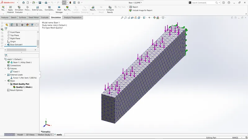
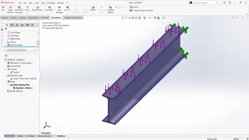
- Boundary conditions:This includes the fixtures, loads, values of loads, initial conditions of the model, material of the model… etc.
- Processing:Software computes the mathematical calculations based on the boundary conditions provided for FEA.
- Post-processing:Visualization of the data form the simulation to obtain result or verify the hypothesis or redesign to obtain the desired outcome.
Case setup
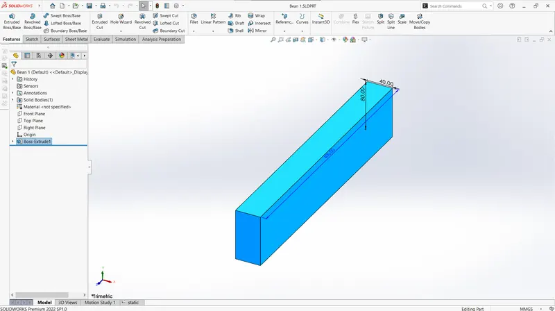
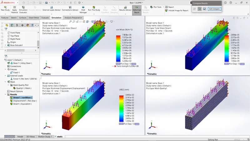
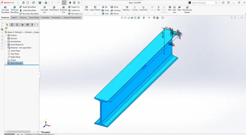
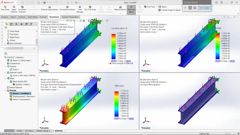
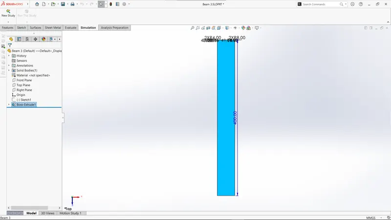
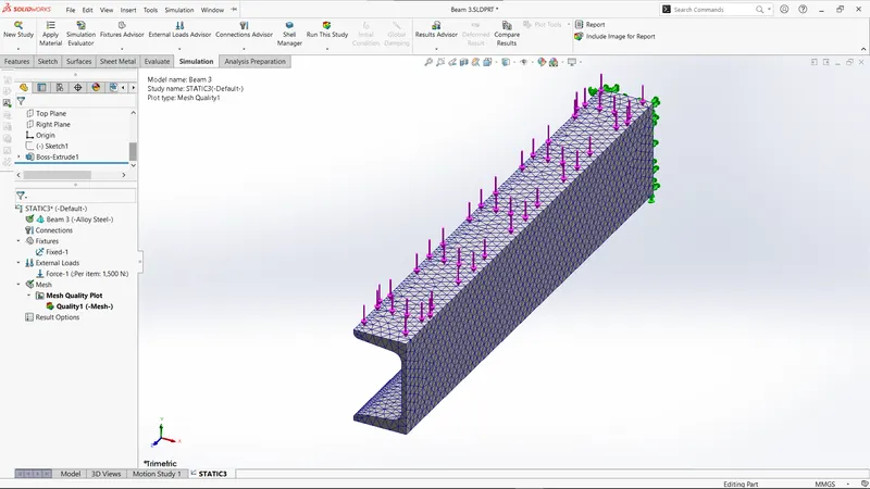
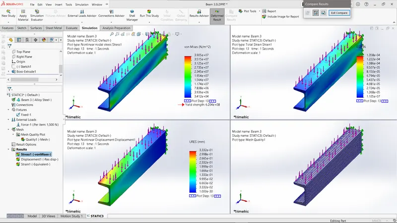
We have three beams of different cross-sections but of length 400mm each and the applied load is 1500N on smaller faces to develop bending in the corresponding beams. By constraining one end of the beam and with the applied force the stress, strain and displacement results are obtained and compared for three different beams taken as:
- case 1-Rectangle beam
- case 2-I beam
- case 3-C beam.
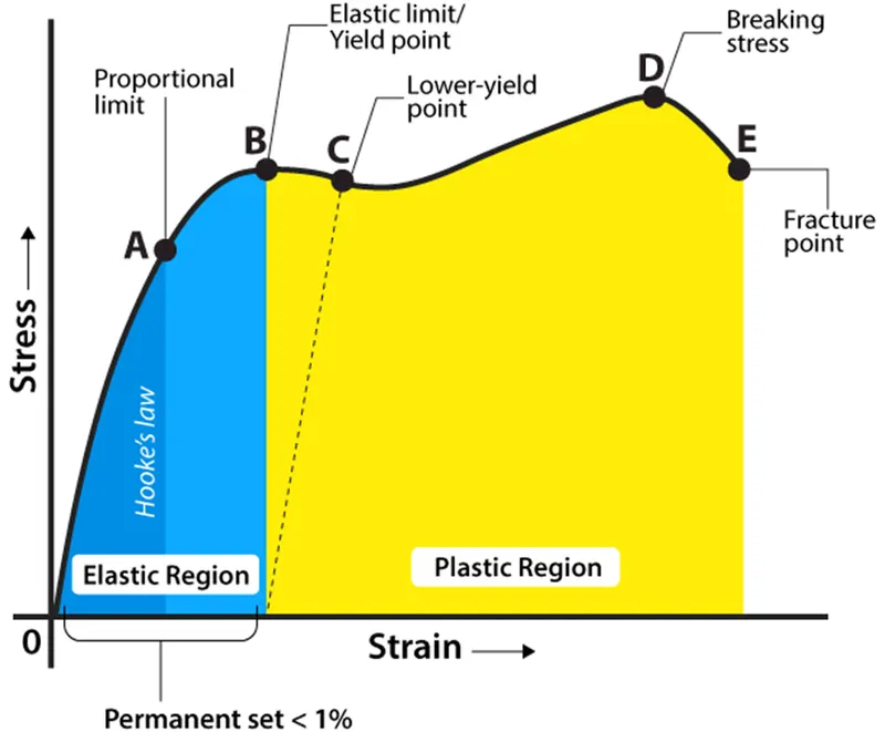
Stress: Stress is defined as force per unit area within materials that arises from externally applied forces, uneven heating, or permanent deformation and that permits an accurate description and prediction of elastic, plastic, and fluid behaviour. Stress is given by the following formula:
σ=F/A
where,
σ is the stress applied, F is the force applied and A is the area of the force applied. The unit of stress is N/m2.
Strain: strain is the amount of deformation experienced by the body in the direction of force applied, divided by the initial dimensions of the body. The following equation gives the relation for deformation in terms of the length of a solid:
ϵ=δl/L
where,
ϵ is the strain due to the stress applied, δl is the change in length and L is the original length of the material. The strain is a dimensionless quantity as it just defines the relative change in shape.
Displacement: it is defined as the change in position of an object. It is a vector quantity and has a direction and magnitude. It is represented as an arrow that points from the starting position to the final position. For example- If an object moves from A position to B, then the object’s position changes. This change in position of an object is known as Displacement.
Displacement = ΔX= Xf-X0
Xf = Final Position, X0 = Initial Position, ΔX = Displacement
BEAM 1:
BEAM 2:
BEAM 3:
CONCLSION
FEA using solidworks is always helps to manufacturers on choosing the best product and its material used, how much load it will withstand before starting its production. Here also same process for three different types of beams but same conditions and inputs.