Centrifugal pump design and analysis
OBJECTIVE
- Run the parametric study of a centrifugal pump for different velocity at outlet
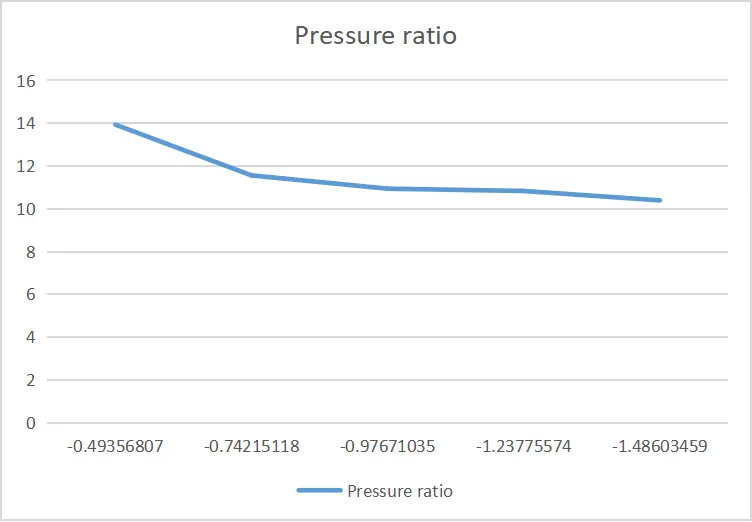
- Plot the pressure ratio vs mass flow rate
THEORY
- CENTRIFUGAL PUMP
Centrifugal pumps are used to transport fluids by the conversion of rotational kinetic energy to the hydrodynamic energy of the fluid flow. The rotational energy typically comes from an engine or electric motor. They are a sub-class of dynamic axisymmetric work-absorbing turbomachinery. The fluid enters the pump impeller along or near to the rotating axis and is accelerated by the impeller, flowing radially outward into a diffuser or volute chamber (casing), from which it exits.
Common uses include water, sewage, agriculture, petroleum and petrochemical pumping. Centrifugal pumps are often chosen for their high flow rate capabilities, abrasive solution compatibility, mixing potential, as well as their relatively simple engineering. A centrifugal fan is commonly used to implement a vacuum cleaner. The reverse function of the centrifugal pump is a water turbine converting potential energy of water pressure into mechanical rotational energy.
Like most pumps, a centrifugal pump converts rotational energy, often from a motor, to energy in a moving fluid. A portion of the energy goes into kinetic energy of the fluid. Fluid enters axially through eye of the casing, is caught up in the impeller blades, and is whirled tangentially and radially outward until it leaves through all circumferential parts of the impeller into the diffuser part of the casing. The fluid gains both velocity and pressure while passing through the impeller. The doughnut-shaped diffuser, or scroll, section of the casing decelerates the flow and further increases the pressure.
PROCEDURE
- Creation of 3D model of centrifugal pump
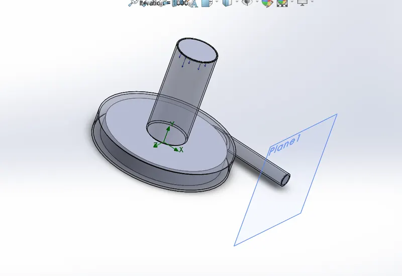
- Creation of a zone near the impeller for moving reference frame
- Simulation Setup
- Analysis type - Internal
- Steady state solution
- Fluid - Water
- Flow type - Laminar and Turbulant
- Rotation - Local region (averaging)
- Boundary Condition at Inlet - Enviornmental pressure
- Boundary Condition at Outlet - Velocity (10 m/s)
- Meshing (Advance channel refinement)
- Adding Goals (Total pressure at inlet and outlet & mass flow rate at outlet)
- Adding cutplots for velocity
- Adding flow trajectory
- Adding Goal plots
- Parametric Study
- Create a new parametric study
- Simulation parameter - Outlet velocity ( Select outlet velocity and use discrete values option to create 5 different cases ranges from 10 to 30m/s )
- Output parameters - Goal, Cutplot and Flow trajectory
- Run
3D MODEL OF CENTRIFUGAL PUMP
RESULTS

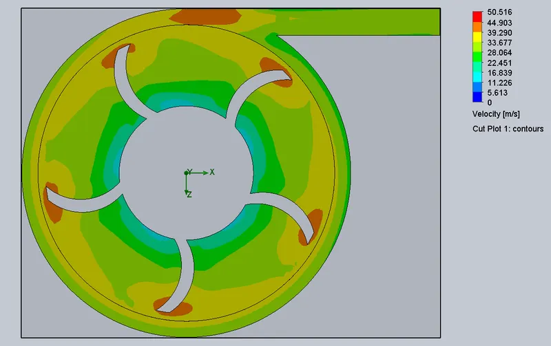
1.Cutplots - Velocity
- Velocity = 10m/s
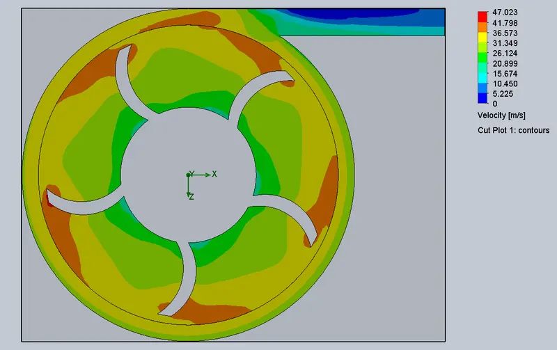
- Velocity = 15m/s
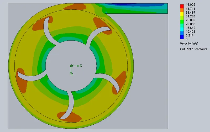
- Velocity = 20m/s
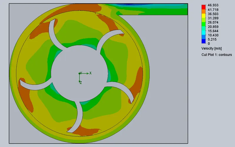
- Velocity = 25m/s
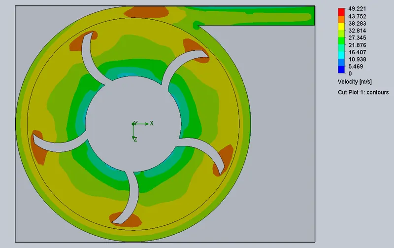
- Velocity = 30m/s
2.Flow Trajectory
- Velocity = 10m/s
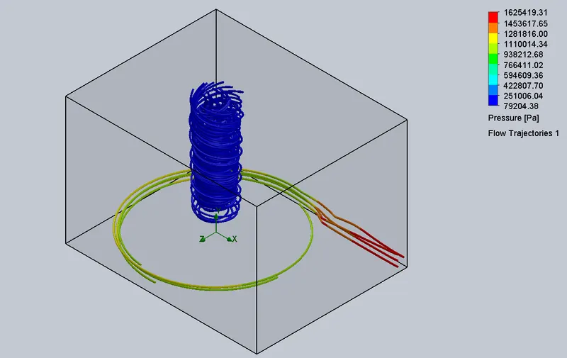
- Velocity = 15m/s
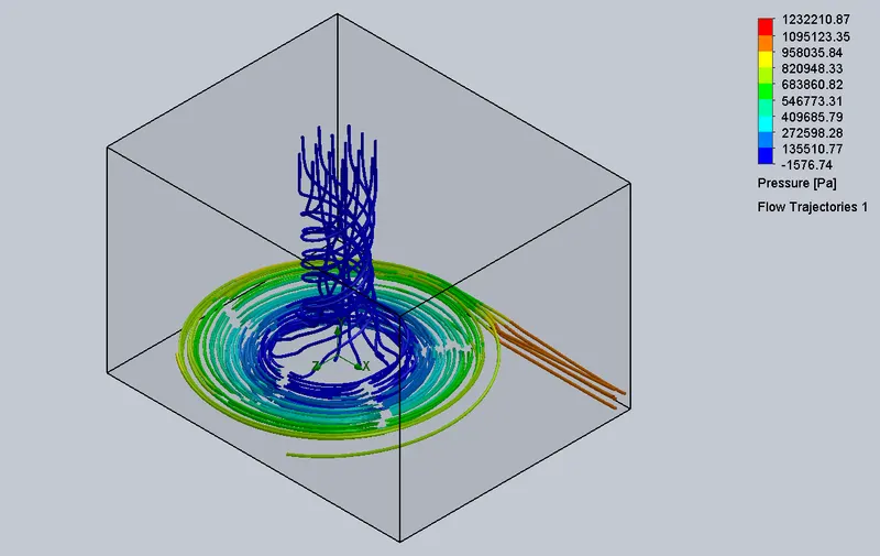
- Velocity = 20m/s
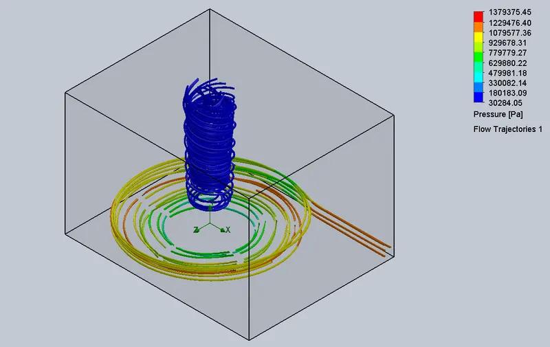
- Velocity = 25m/s
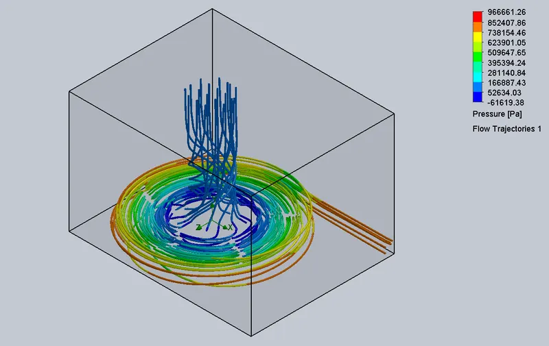
- Velocity = 30m/s
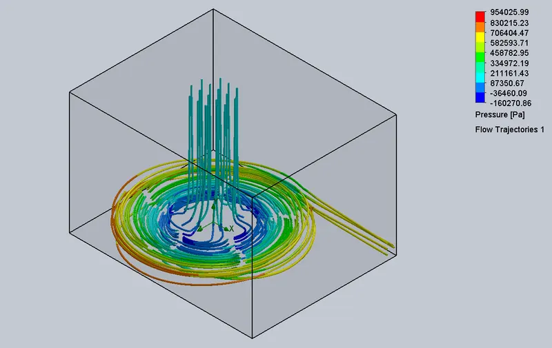
3.Pressure Ratio - Mass flow rate graph
CONCLUSION
- In the first figure we can see that, initially the velocity is less because of that the mass flow rate is also less, if when velocity increase then mass flow rate is also increases.
- Inlet pressure remains the same for all the cases but the outlet pressure varies. When the flow rate at the outlet is high the pressure reduces at outlet which results in the decrease in the pressure ratio.
-
From the First plot we can see that initially the velocity is less so the mass flow rate is less when the velocity increases the mass flow rate increases.
-
From the Second plot we can see that, pressure ratio is high for low velocity and pressure ratio starts to decrease when the velocity increases.
-
From the Third plot we can see that for lower mass flow rate the pressure ratiois high when the mass flow rate increases pressure ratio decreases.