Braking of Electric Motors
1) For a defined driving cycle, calculate the energy required for braking.
The energy required for braking would be the same energy required for acceleration. Suppose the car accelerates to a certain speed; to bring that speed down to zero by hitting the brakes would be referred to as braking energy. Therefore, the amount of work done to accelerate would be the same amount of work done needed for braking.
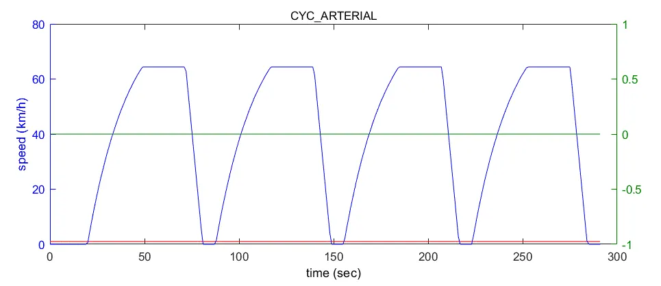
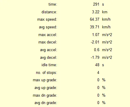
Through the ADVISOR tool in MATLAB, the ARTERIAL CYCLE has been chosen as the defined driving cycle. Other popular cycles such as FTP or UDDS were avoided because this one is much simpler and perfectly appropriate to answer this question.
Using an excel calculator:
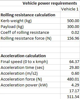
- Referring to the drive cycle data, for a max speed of 64kmph and the average acceleration being 0.6m/s2, the time it takes for acceleration from 0 to max speed is 29.8 seconds. That results in an acceleration, hence braking power, of 4.29kW.
- There are four instances in the drive cycle (see above) that the vehicle accelerates the same way, making the total braking power 4.29x4 = 17.17kW for a vehicle of mass 800kg
- Total braking energy would be 17.17kW x 29.8s of acceleration time = 511.54kJ
2a) Why can't an electric motor develop the kind of braking torque that it does at the start at high speeds?
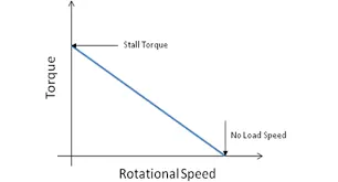
`T = (kV - k^2omega)/R` ----------- inversely proportional relationship between speed and torque: the higher the motor speed, the lower the torque
As can be seen in the figure above, starting (or stall) torque is the highest torque a motor can develop. As the motor speed gets higher during motoring of the vehicle, the torque reduces, and therefore peak braking torque is always lesser than peak motoring torque too, not just starting torque.
2b) How are electric and mechanical brakes coordinated?
Mechanical braking refers to the mechanism where the friction between the brake pads pressed against the rotating wheels reduces the speed of the vehicle. All the energy through this mechanism is lost to heat as part of the friction created.
Electric braking is an engineering marvel, also referred to as regenerative braking, that is available in HEVs/EVs. With this mechanism, when the brakes are applied, the kinetic energy of the wheels are transferred back to the motor-turned-generator, that converts it into electrical energy and charges the battery with it.
How they are coordinated:
Above is an example of the brake control strategy Nissan came up with for its Nissan Leaf EV. Since both mechanical and electric braking are to be used, intuitively it would make sense to majorly use mechanical brakes at lower speeds, as this would result in generation of little heat and minimal wear and tear of the two surfaces in contact. Likewise, using electric brakes at higher speeds would mean a lot of energy saving and lower usage of fuel since the battery can be recharged with the amount of kinetic energy the vehicle is carrying at higher speeds.
However, when referring to the control strategy by Nissan in the above figure, they have gone with the opposite i.e. more mechanical braking at higher speeds and more energy saving via regenerative braking at lower speeds through electrical braking. Why is that?
The answer lies with the battery charging current limitation for regenerative braking. When brakes are pressed at high speeds, it is certain that the vehicle is carrying a lot of kinetic energy that could be reused, however, high speed braking also results in peak braking torque and thus a big inrush of current (`T = k_TI_a`) into the generator and battery, and often it exceeds the charging current limitation. Thus, to keep the generator and battery from experiencing this sudden inrush of current which could destroy the motor windings and other temperature sensitive parts, design and manufacturing engineers decide to use more of mechanical braking than regenerative, especially since regenerative isn't as efficient at higher speeds anyway. At lower speeds, the braking torque is lesser and the produced energy can be fully used to charge the battery, so the regenerative:mechanical ratio increases almost exponentially as vehicle speed lowers linearly.
This certainly is a problem, as charging current limitation doesn't allow for huge amounts of braking energy (which is available at higher speeds) to be used to charge the battery through regenerative braking. Imagine the amount of fuel saving that could be done if this problem were solved.
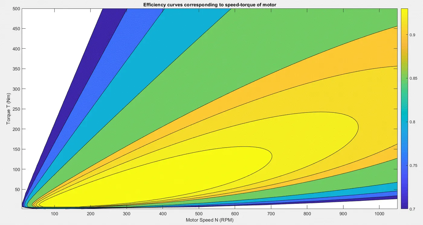
3) Make a MATLAB program which plots contour of given motor speed, torque and efficiency values.
Code:
%-------Plotting contours of motor speed, torque, and efficiency----------
clear all; close all; clc

w = linspace(1,110); %rad/sec
N = (w.*60)/(2*pi); %motor speed converted to RPM
t = linspace(1,500); %Nm
[N,t] = meshgrid(N,t);
kc = 0.2; %copper loss constant
ki = 0.008; %iron armature loss constant
kw = 0.00001; %windage (friction) loss constant
const = 20; %constant motor losses (miscellaneous)

CL = (t.^2).*kc; %copper losses (I2R)
IL = ki.*N; %iron losses
WL = (N.^3).*kw; %windage losses
Total_Losses = CL + IL + WL + const;

Power_OUT = t.*N; %P = Tw
Power_IN = Power_OUT + Total_Losses;
eff = Power_OUT./Power_IN;
n = [0.70 0.75 0.80 0.85 0.90 0.91 0.92 0.93]; %efficiency for contour lines

contour(N,t,eff,n);
xlabel('Motor Speed W (RPM)')
ylabel('Torque T (Nm)')
title('Efficiency curves corresponding to speed-torque of motor')
colorbar
Output: