Body side Outer Panel for an SUV
Objective: :
Design and development of automotive Body side Out for an SUV. Design individual components and attach them to the rest of the SUV body. We need to model these parts in such a way that they can be welded together.
Automotive Body Side Outer:
The car body side refers to the exterior surface or panel on the side of a vehicle. It is the outer layer of the car's body that encloses the interior space and protects the vehicle's occupants and components.
- A Pillar:The A-pillar is a structural component of a vehicle's body that supports the windshield and provides structural integrity to the front of the vehicle. It is located on either side of the windshield, forming the boundary of the front side windows. The A-pillar typically extends from the vehicle's roof down to the front fender or the base of the vehicle's body. It plays a crucial role in maintaining the structural strength and safety of the vehicle, especially during frontal impacts or rollover accidents. Fig.(a) A Pillar
- B Pillar:The B-pillar is a vertical structural component of a vehicle's body located between the front and rear doors. It provides support and stability to the roof structure of the vehicle. The B-pillar is typically thicker and stronger compared to the other pillars in the vehicle, as it helps enhance the overall rigidity and crashworthiness of the car. In many vehicles, the seat belts for the rear passengers are also anchored to the B-pillar. The B-pillar plays a vital role in maintaining the structural integrity and safety of the vehicle in the event of a collision or rollover. Fig.(b) B Pillar
- C Pillar:The C-pillar is a vertical structural component of a vehicle's body located at the rear end, behind the rear passenger doors (if present). It provides support and structural integrity for the rear portion of the vehicle. The C-pillar is usually thicker and more robust than the other pillars, as it helps support the roof and contributes to the overall rigidity of the vehicle's structure. The design and shape of the C-pillar can vary among different vehicle models and can significantly affect the vehicle's aesthetic appeal. Additionally, the C-pillar often houses features such as rear side windows and may play a role in the overall aerodynamics of the vehicle Fig.(c) C Pillar
- Sill body:The sill body, also known as the rocker panel or side sill, is a structural component located on the sides of a vehicle, typically between the front and rear wheel wells. It runs horizontally along the bottom edge of the car's body, connecting the front and rear fenders. The sill body provides support and rigidity to the vehicle's structure and helps protect the interior from damage. It also serves as a visual element, contributing to the overall design and aesthetics of the car. Fig.(d) Sill Body Region
- Bumper and lamp mounting region:The bumper region refers to the area of a vehicle's front or rear where the bumpers are located. Bumpers are designed to absorb and distribute impact forces in the event of a collision, helping to protect the vehicle's occupants and minimize damage to the vehicle's body. The bumper region often includes additional components such as bumper covers, energy absorbers, reinforcement bars, and sometimes sensors or cameras for advanced driver assistance systems (ADAS). The specific design and composition of the bumper region can vary among different vehicles, but its primary purpose is to enhance safety and protect the vehicle during impacts.So for designing it, we used reference of styling of bumper mount and then created bumper.
Fig.(e) Bumper Region
- Gas Stay Retraction Area:The retraction area of a gas strut generally refers to the part or region of the strut where the piston retracts when the tail gate it is supporting or assisting is in the closed or lowered position. When the tail gate or back door is opened or lifted, the gas strut extends, pushing the piston out of the retraction area and generating the necessary force to hold the component in an open or raised position.So for designing it, we used two references. one is the back door, and the other is the roof, and then created the flanges.
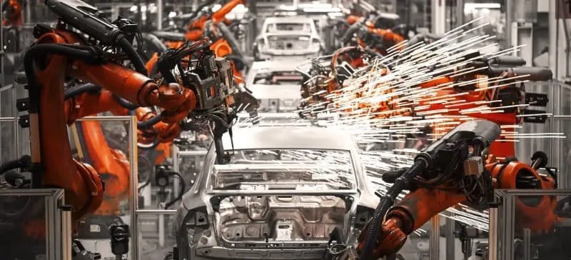
Automotive Metal Forming Technologies:
One of the most important things about metal is that it can undergo plastic deformation.
The process of deformation begins with a blank, a quantity of metal in some basic form that will undergo a change in shape. The blank becomes the workpiece—the piece of metal to be reshaped—in the metal-forming process. For automotive metal forming, the blank is often made of sheet metal, which can be stamped, cut, or bent into the shape needed for an automobile's body. Alternatively, it can be a solid block of metal in a cubical or lens-like shape. Here are some ways that a metal workpiece can be deformed during the automotive manufacturing process:
1. Blanking:Blanking is a sheet metal forming process that involves cutting a flat piece of metal into a desired shape. This operation is typically carried out using a punch and die set, where the punch creates the desired shape by shearing the metal against the die. The excess metal is then discarded as scrap.
2. Punching:Punching is a sheet metal forming process that involves creating holes or other shapes in a piece of metal using a punch and a die. The punch pushes through the metal and into the die to create the desired shape. This process can be done manually or with a machine, and it can create a variety of shapes and sizes depending on the punch and die used. Punching is commonly used in the production of small metal components, such as bolts and screws, and in the automotive industry to create holes in car body parts for assembly.
4. Drawing:In drawing, the sheet metal is forced against a die that has been cut into the three-dimensional, often curved shape that the sheet metal is to take on.This technique can produce relatively complex shapes. Once again, pressure is applied to the workpiece using a hydraulically or mechanically operated punch.This method is commonly used to make auto body parts and fuel tanks.
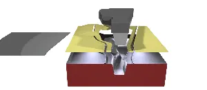
Fig.(l) Drawing Process Fig.(m)Blanked sheet example
5.Bending:In bending, force is applied to a sheet metal workpiece to produce a curvature of the surface. Bending is generally used to produce simple, curved surfaces rather than complex ones. A mechanically operated press drives a punch against sheet metal, forcing it into a simple die with enough pressure to produce a permanent change in the metal's shape. The amount of pressure is important. If not enough pressure is applied, the metal can simply spring back into its original shape. If too much is applied, it can break.
Fig.(n) Bending
7. Stamping:A tool called a stamping press and a number of dies are used in the process of stamping to cut and shape metal into different shapes.The dies exert external forces on plates, strips, pipes and profiles to produce plastic deformation or separation so as to obtain the required shape and size of workpieces
There are three popular types of metal stamping presses used for automotive and other industrial parts. They include:
- Mechanical presses, which have a mechanical flywheel powered by a motor.
- Hydraulic presses, which have pressurized fluids that control the pressure and application of force on a workpiece.
- Mechanical servo presses, which use only motors and no mechanical flywheels.
Below are the snapshot of the required design as per data given:
Fig. (o) Three views of model
Conclusion:
As a result, I applied proper design techniques and created the necessary reinforcements and embosses for the provided stylistic surface of a side door design.As a result, I created an outer side door for an SUV car.