Bird Strike Using LS-DYNA
BIRD STRIKE WITH PLANE
INTRODUCTION
A bird strike is not a rare event, to say. From literature, it was found that 8 out of 10,000 planes are affected by bird strike events. Although, engines of planes are designed like they can withstand a minimum of 3.5 kg of birds (without debris), if one engine gets failed, it can cross half of the ocean on another engine. Birds generally fly as high as 150 m. This is the height where, the plane would be in the position of taking off or landing, in which case, the speed of the plane is slower than when it flying. Thus, many reports have shown the accident in case of taking-off and landing. However, it has also been reported at a high altitude of 6000 to 9000 mts. It has also been observed that 5% of bird strike results in damage to the plane. In that plane has to land at a nearby airport.
This work was undertaken to study the procedure of modeling this case, analyzing it, and drawing out the conclusion, using LS-Dyna software.
PROCEDURE
The FE model of the engine and the bird was available to analyze, as shown in the figure below. The model consisted of the casing, blade, hub, and bird. The bird model was shown as a cylinder, as only the representation is enough to analyze, rather than complicating the case. The bird although was given the material property of the bird itself.
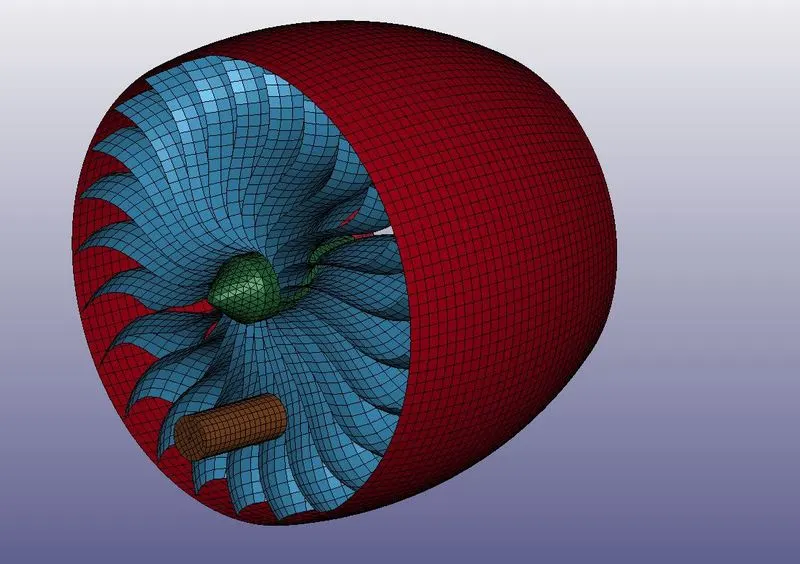
Figure 1: FE model of airplane’s engine and bird.
Before, proceeding to assign material and other things, the model was first separated. In other words, each part of the model was saved as a separate file.
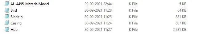
Figure 2: Each part of the model was saved as a separate file.
Material & Section
Now, to each part, the material and section card was assigned.
Casing:
The casing is the heaviest part of the engine, therefore, for that, light materials like titanium, aluminum, or CFRP material are used. However, to avoid complications at the initial stage of modeling, steel material was assigned to it, using *MAT_ELASTIC card.
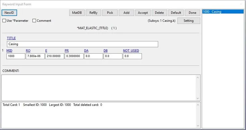
Figure 3: *MAT_ELASTIC card with steel material property assigned to the casing.
Next, the section card was used to assign the thickness of 5 mm to the casing.
Every engine-making company has its own standards for designing the parts. So, this is the case for airplane engine-making companies. Now, because of the unavailability of the standard dimensions of the thickness of the casing and other parts, thicknesses were taken arbitrarily. The only of this work was to study and understand the procedure.
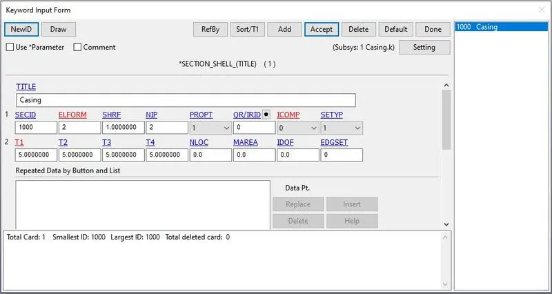
Figure 4: *SECTION_SHELL card to assign the thickness of 5 mm to the casing.
Blades:
For the blades of the engine, a material card was available, as can be seen in fig. 2 (File Name: AL4495-MaterialModel). Now, to assign that material to blades, the file containing blades was opened. In that, *INCLUDE card was used to which the path of the material card was given, as shown in the figure below.
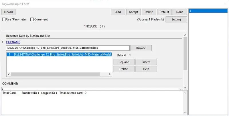
Figure 5: *INCLUDE card to include a material card to the blades containing the file.
The file saved, ls-dyna application closed, and re-opened, and opened the Blades file. Now, as can be seen in the figure below, the material card was included in the Blade-s file.
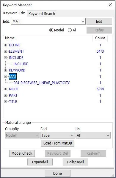
File 6: Available material file included in the Blade-s file, using *INCLUDE card.
The plot of material data is shown in the figure below. From the figure, the data seems like stress (in kN/mm^2)-strain (in mm/mm) curve.
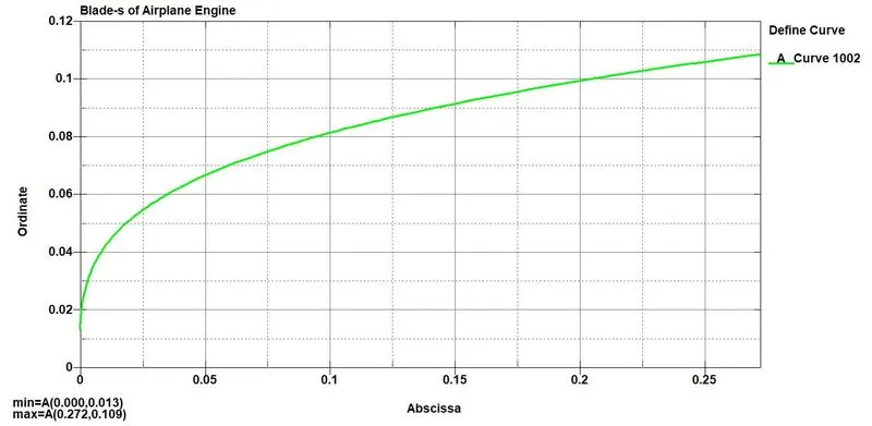
Figure 7: Material data, available for the blades of the engine.
From fig. 8, it can be seen clearly that the material of the blade is aluminum.
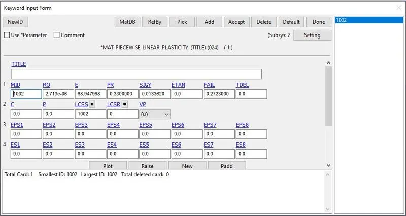
Figure 8: Material card for blades of engine.
Similar to the casing as shown in fig. 4, after material, the section card was created using *SECTION_SHELL, for the blades, to assign it the thickness of 3 mm.
Hub:
For the hub, *MAT_PIECEWISE_LINEAR_PLASTICITY material card was used. It was provided the steel material property in (Kg, mm, ms) unit system.
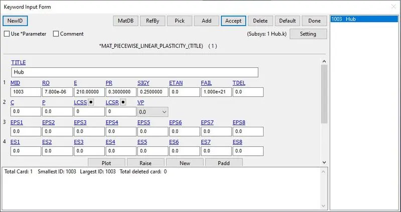
Figure 9: Material card for the hub.
The hub was composed of solid elements, therefore, *SECTION_SOLID card was used for the hub.
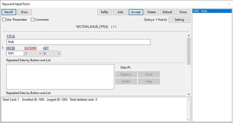
Figure 10: Section for solid elements of the hub of the propeller.
Bird:
In reference [3], the density of the bird was taken as 942.7 kg/m^3, and Poisson’s ratio of 0.45. Thus, in this work, the bird was assigned the material property accordingly, using *MAT_ELASTIC card.
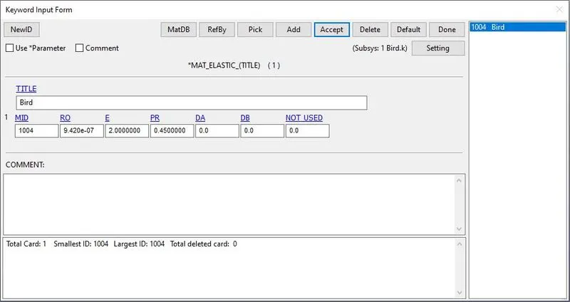
Figure 11: Material card for the bird.
Similar to the casing, the same *SECTION_SHELL card was applied to the bird, with 2 mm of thickness.
This is how, all the parts were saved in separate files, and assigned to them as material and section property. Now, to import all of those files into one single file, another blank/new file was opened in ls-dyna. Using *INCLUDE card, all those files were included. The file was saved, closed, and reopened. The model looks exactly like as shown in fig. 1.
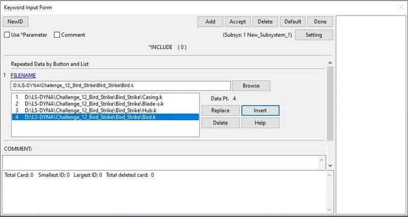
Figure 12: *INCLUDE card to include all of the files in one file.
When all the files are included in one file, a part set was created for each part using Model & Part → Create Entity → Set Data → SET_PART.
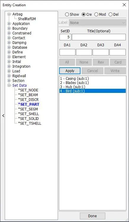
Figure 13: Part set created for each part of the model.
Contacts
Between Birds and Blades
When the bird hits the blades, the first that would occur is in between the bird and blades. Thus, *CONTACT_AUTOMATIC_SURFACE_TO_SURFACE contact card was created between the bird and the blades. Now, the bird being less stiff than the blades, it was taken as a slave, and the blades were taken as master.
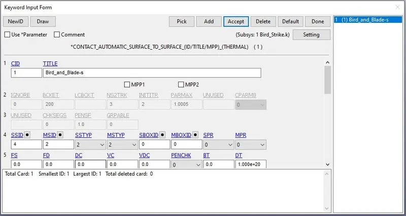
Figure 14: Automatic surface-to-surface contact between bird and blades.
Between Blade-s and Blade-s
If the bird is going to damage the engine, the second contact would occur between blades with each other. It means, the blades will hit themselves. Therefore, *CONTACT_AUTOMATIC_SINGLE_SURFACE contact card was created for this case. In this case, the master is not required, it works only by defining the slave. Thus, the slave is defined with blade-s.
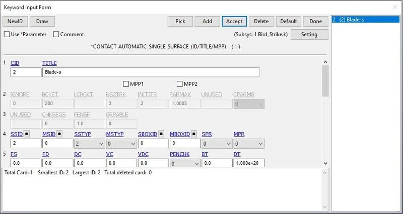
Figure 15: Automatic single surface contact card for blades.
Between Blades and Casing
The third contact, after damage, would occur between the blades and the casing. Thus, *CONTACT_AUTOMATIC_SURFACE_TO_SURFACE contact card was used. In here, the casing being stiffer than blades, it was taken as master, and the blades were taken as slaves.
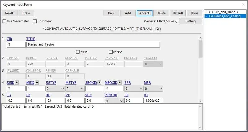
Figure 16: Automatic surface-to-surface contact between blades and casing.
Between Blades and Hub
The contact between the hub and blades is the only contact that remains constant before and after the damage. Thus, *CONTACT_TIED_SURFACE_TO_SURFACE contact card had to create between blades and hub. But it is recommended that the tied contact has to be defined between nodes to nodes and not between part ids. Therefore, at first, a node-set was created for the blades and the hub each. Then, the tied contact card was created, as shown below, in which nodes of blades were set as slaves and nodes of the hub were set as masters.
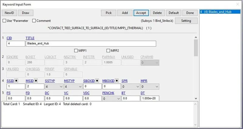
Figure 17: Tied contact between blades and hub.
Boundary Condition
Initial Velocity to Bird
According to National Technical Systems, Inc., they give the velocity of 400 mph or ~180 mm/ms to birds (either real or gelatine substitutes), for testing the engines. According to American aerospace manufacturer Pratt & Whitney, they consider the speed of a bird is 200 knots (230 mph) or ~100 mm/ms. There is too much deviation between standards. Therefore, in this work, the average was taken i.e., 140 mm/ms.
Using *INITIAL_VELOCITY_GENERATION, the velocity of 140 mm/ms was given to the bird in the direction of the engine.
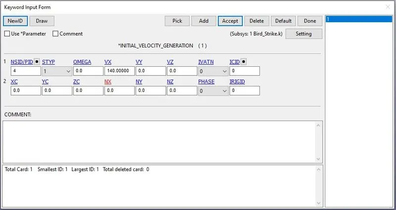
Figure 18: Initial velocity of 140 mm/ms was given to the bird.
Angular Velocity to Hub
In-flight, the fan blades spin at around 3,000 RPM, or 0.3 radians per milli-seconds. Thus, using, *INITIAL_VELOCITY_GENERATION, 3000 rpm speed was given to the hub, and thus the blades (because they are tied).
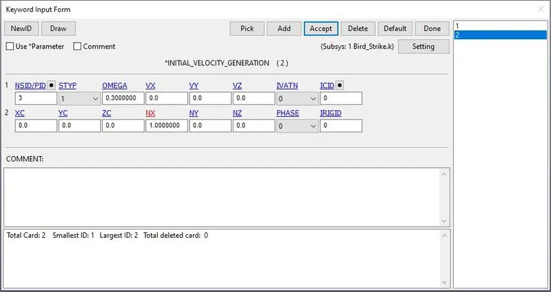
Figure 19: Initial angular velocity of 3000 rpm was given to hub.
Fix the Casing
The casing of the engine remains as it is, even after the damage. Thus, it had to be fixed in all directions. Using, Model and Part → Create Entity → Boundary → Spc, nodes of the casing were fixed in all directions.
Constrain Blades and Hub
After the impact, the blades and hub should not move in other directions and remain on their own axis. Therefore, Model and Part → Create Entity → Boundary → Spc, are constrained to not move in the x-axis.
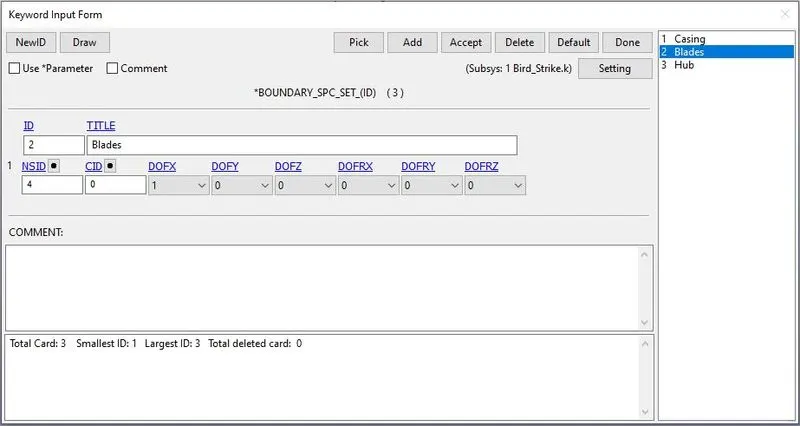
Figure 20: Blades constrained to not move in the x-axis.
Constant Speed of Hub and Blades
After impact, it is certain that the rotational velocity of the blade would reduce, which is not the case in real-time. Because a drive is provided to it. To replicate this, a curve was defined using *DEFINE_CURVE. The plot was drawn for constant speed as shown in the figure below.
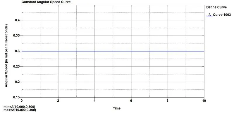
Figure 21: Plot for constant angular speed of blades.
Using *BOUNDARY_PRESCRIBED_MOTION_SET, this curve was defined to the blade and hub, together.
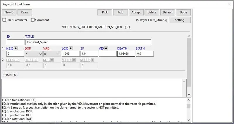
Figure 22: Constant angular speed was given to hub.
Renumbering
One of the tasks of this work was to, renumber the nodes, elements, and parts. In other words, 100000+ numbering for nodes, 500000+ numbering for elements, 1000+ numbering for parts, and all other keywords numbering should be within 10000-19999. Using Model and Part → Renumber, everything required was renumbered.
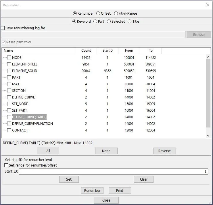
Figure 23: Renumbering of everything was done, as required.
Control Cards
The simulation had to run for 10 ms. Therefore, *CONTROL_TERMINATION card was used, in which ENDTIM value was given as 10. The *CONTROL_TIMESTEP card was also included to control the timestep if required.

Figure 24: Simulation time was set to 10 ms.
Output Request
In the output, *DATABASE_BINARY_D3PLOT card was used to request animation files every 0.1 ms. Along with this, using *DATABASE_ASCII_option, GLSTAT (global statistics), MATSUM (Material Energies), RCFORC (Resultant Interface Forces) was also requested.
Solver & Postprocessing
When the run was started, with setting in *CONTROL_TIMESTEP card, which is, DTINIT = 0.01, TSSFAC = 0.9, and DT2MS = -1.0E-05, for 5 ms of analysis. It was observed that the was taking around 12 hrs to solve, with no mass increase.
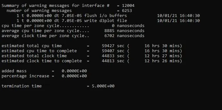
Figure 25: Estimated time at first run.
Therefore, the run was stopped, the value of DT2MS was increased to -1.0E-04, and the run started again. Now, this time, the estimated time was reduced to 3 hrs 14 mins, with mass increased by 5.42E-03%, which is negligible. However, the actual time had to be less than what was estimated, therefore, the run was let to complete.
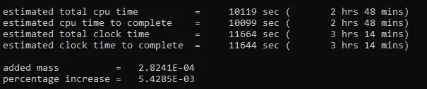
Figure 26: Estimated time at a second run.
The problem actually terminated normally, within 6 minutes and 37 secs.
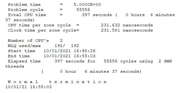
Figure 27: Problem terminated normally within 7 minutes.
The problem was then checked with Von-Mises stress contour. In the animation below, it can be observed, that there is no stress level on the frees ends of the blades. However, there some stress can be seen at the blades and hub contact. This is because, that was stationary, and the hub had to provide a drive to them. Now, because of the inertia of the blades, this increase in stress level is there.
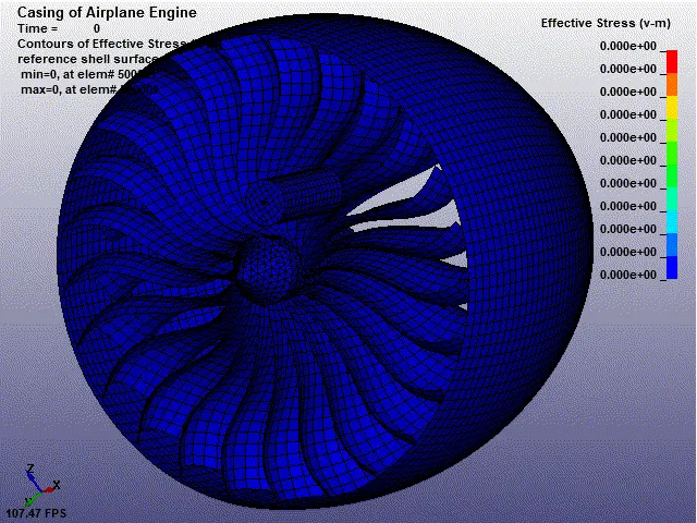
Figure 28: Von-Mises stress contour.
The simulation appeared to be perfect, as expected. Now, when the bird hit the blades at a speed of 140 mm/ms, which was running at 3000 rpm, the damage occurred to 2 blades. However, the entire engine was still running perfectly. No disturbance is observed. When practically, the bird has to tear apart, and shouldn’t be seen as it is appearing in the animation. But, because it was the first attempt, it was acceptable.
In the energy plot, it can be observed that when the kinetic energy was decreased slightly, the internal energy increased by the same amount. The total energy is decreased slightly at the start, or when the bird actually touched the blades. This shows the presence of some amount of error. However, it remained constant thereafter.
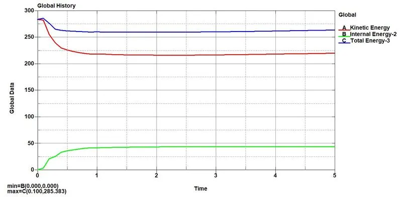
Figure 29: Plot of energies vs. time.
In the figure below, 509569 is the element id of the element of the bird, and 508089 is the element id of the deforming blade. The stress level is in GPa. From the figure, it can be observed that the bird is undergoing a stress level of around 65 MPa, which can be imagined as ~12000 kg of load for the bird with 50 mm diameter. A bird definitely cannot survive at this much load. But ~55 MPa of maximum stress on blades, is still acceptable.
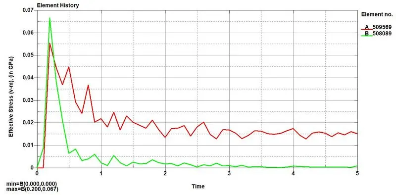
Figure 30: Comparison of stress level on blade and bird.
However, the whole scenario can be different, because, many assumptions were considered in this work.
CONCLUSION
The objective of this work was to replicate the event of a bird strike with an airplane engine. For this, the model had to make ready with material, element formulation, contacts, boundary condition, and some simulation control parameters. All of these were performed perfectly, but with some assumptions. The assumption was needed because of the unavailability of some data, and because it was the first attempt. However, the simulation appeared much practical. This can become more practical with some actual data of birds, and blades.
References
[3] Dr. Mohamed Zakaulla, Innovative Processing Methods for Synthesizing Advanced Structural And Functional Materials, RED'SHINE Publication. Pvt. Ltd