Bird Strike - Project - 2
Objective:
To perform Transient-non linear bird strike simulation where the birds hits the gas turbe blades - Using LS-Dyna
Theory:
Bird strikes are a major threat to aircraft structures, as a collision with a bird during flight can lead to serious structural damage. Computational methods have been used for more than 30 years for the bird-proof design of such structures, being an efficient tool compared to the expensive physical certification tests with real birds. At the velocities of interest, the bird behaves as a soft body and flows in a fluid-like manner over the target structure, with the high deformations of the spreading material being a major challenge for finite element simulations. Bird strike simulations on aircraft structures have been performed and improved since the late 1970s. Large variety of bird impactor geometries, materials, masses, densities and modelling methods exists in the literature. there are three established techniques for numerical bird impactor modelling are used: Lagrangian , Eulerian and SPH. Each technique has specific advantages/disadvantages. The best approach depends on the specific application, software package, computational resources and parameter setup.
Procedure:
Case setup & Execution:
1. Separation of Parts:
- The given keyword file BIRD_STRIKE consists of nodes and elements for all the four parts collectively i.e, Engine casing, Blade, Hub and Blade
- we need to keep only one part in each keyword file, such that it is created by deleting all other parts which are not needed.
- Then the keywords are saved in a separate location.
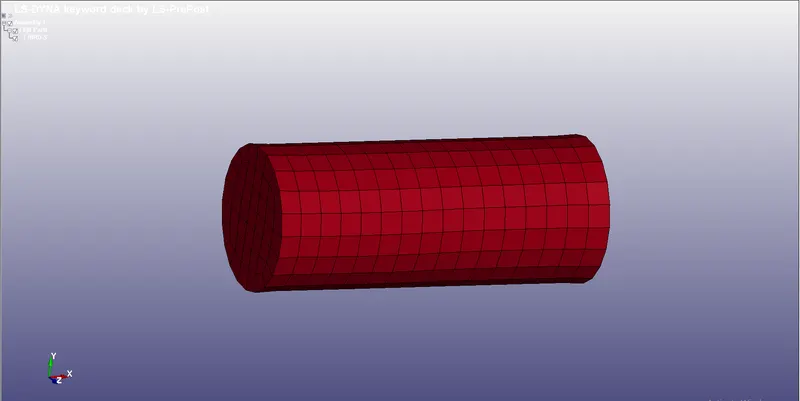
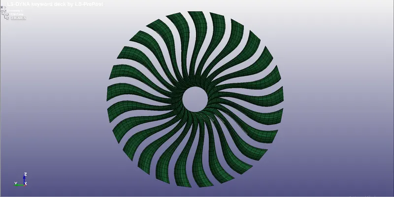
BIRD BLADE
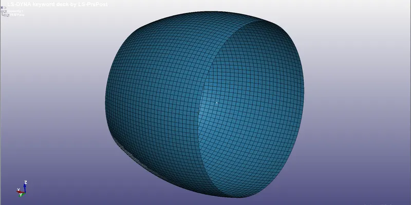
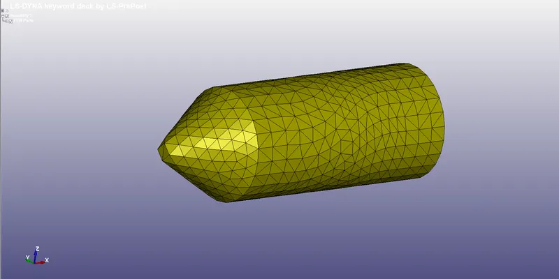
ENGINE CASING HUB
2. Material card creation:
- The Unit system followed here will be Kg, mm, ms
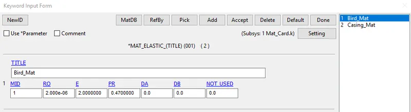
- For bird the material is selected from a journal "https://www.researchgate.net/publication/258630404_Bird-Strike_Modeling_Based_on_the_Lagrangian_Formulation_Using_LS-DYNA"
- From which the density of the bird is taken as 2.0E-06 , with a youngs modulus of 2 Gpa and a poisson ratio of 0.47
- from keyword *MAT_ELASTIC card is taken to assign the values
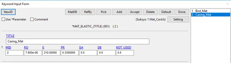
- For Engine casing the same material card is used with the properties of steel is assigned to it
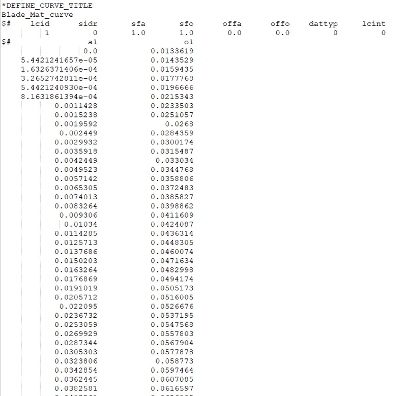
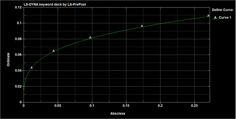
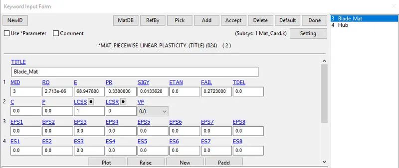
- For blades MAT_24_Piecewise_Linear_plasticity card is assigned with properties of Aluminium and the given Mat curve data is assigned as a load curve for plastic strain behaviour.
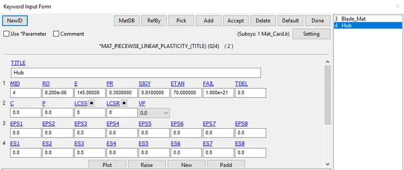
- For Hub the same material card with properties of Steel is assigned
3. Section card Creation:
- Now Section card is created separately in another keyword file.
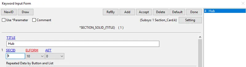
- Since the Hub is a solid element, Section `rarr`Solid is created for it, with a element formulation of 10
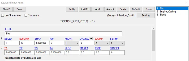
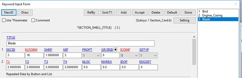
- For the other three parts i.e., bird, blade and engine casing Section `rarr`Shell with element formulation of 16 ( Fully Integrated) is selected.
- For Bird thickness is given as 5 mm For blade 2 mm thickness is assigned.
- For Engine casing thickness is given as 3 mm.
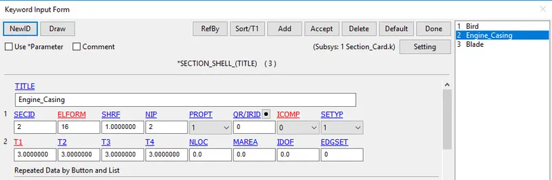
- For blade 2 mm thickness is assigned.
All the keywords which are saved separately for bird, engine case, blade, hub, material card and section card is Included into a single keyword file using the option "Include `rarr`Include"
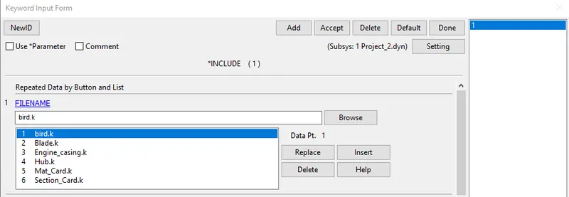
This keyword file is then stored with .dyn extension for easy access, this new keyword files consists of all the above mentioned keywords into one file.
4. Contact creation:
- The ideal scenario is that the bird crashing into the blades, so a contact needed to be defined between the bird as blade
- Hence *CONTATCT_AUTOMATIC_SURFACE_TO_SURFACE is selected with the bird as the slave and blade as the master
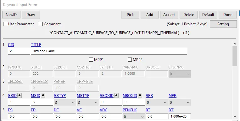
- After impact there is possiblity that the blade might get broken down and collide with other parts for which *CONTATCT_AUTOMATIC_SINGLE_SURFACE is assigned with the blade acting as both the master and the slave.
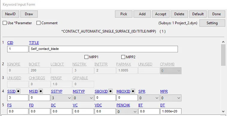
- There is also a possibility that the broken down blade might hit the engine casing
- hence *CONTATCT_AUTOMATIC_SURFACE_TO_SURFACE is selected with blade as the slave and casing as the master
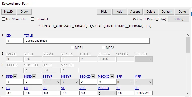
- As we already know that the hub is modelled with solid elements while the blades are modelled with shell elements so they are tied together with *CONTACT_TIED_SURFACE_TO_SURFACE with the hub as the master and the blade as slave
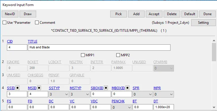
- There is also a slight possibility that the bird after impacting might come into contact with the Engine casing for which *CONTATCT_AUTOMATIC_SURFACE_TO_SURFACE is selected with the bird as the slave and casing as the master
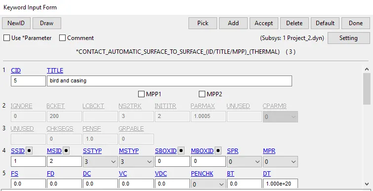
5. Boundary conditions:
(i) Initial velocity:
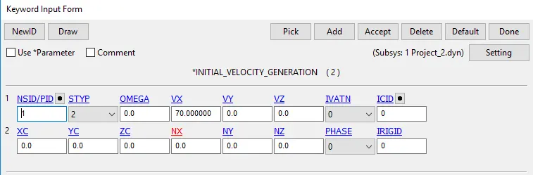
- The Average velocity in which the bird travels is taken from the outsides sources is foundout to be approximately 20 to 80 mm/ms
- So the velocity of the bird is assigned to be 70 mm/ms along the X axis.
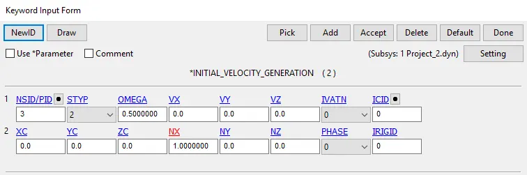
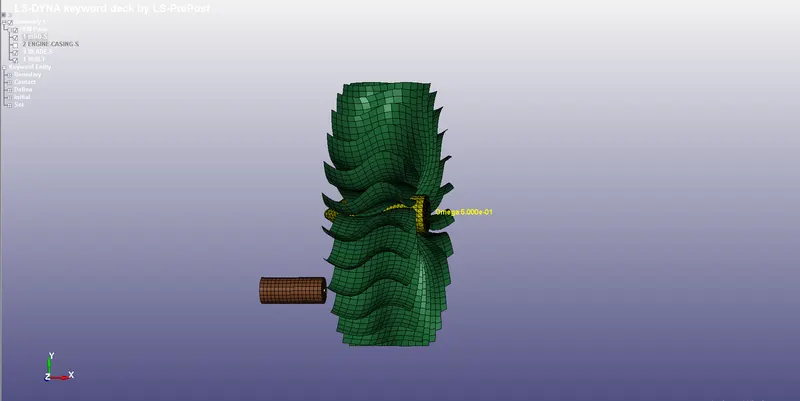
- For the blades angular velocity is needed to be defined, it is known that the average speed of the air craft turbe is around 3000 to 20000 rpm
- here we have considered 5000 rpm from which angular velocity is found out to be 0.5 rad/ms
(ii) Spc:
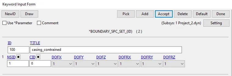
- The Engine case is constrained in all Dof's
6. Renumbering:
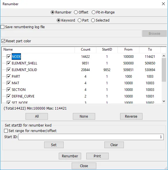
After completing all the above mentioned process, we need to renumber the model in such a way that the numbers would start from 100000+ for nodes, 500000+ for elements, and 1000+ for the parts, All other keywords should be numbered within 10000-19999 this is done in consistant numbering approach which is commonly follwed in industries while dealing with complex projects.
7. Control cards:
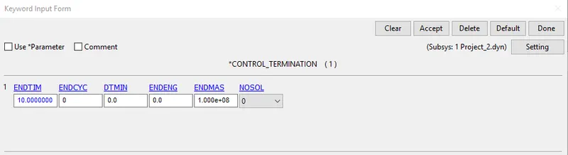
- Run time of the simulation is set to 10 ms using the Control termination card
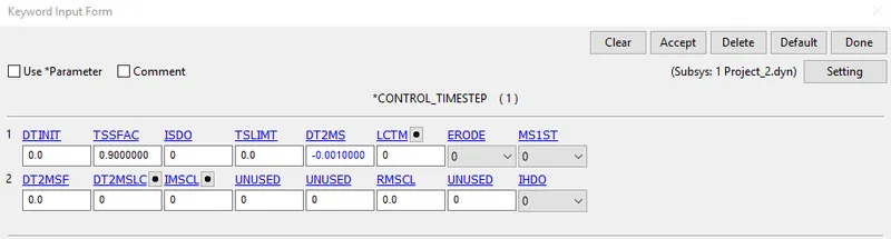
- For mass scaling Control time step card is given with D2MS value of -0.001 and tssfac of 0.9
8. Output Request:
- Generally output resquest are specified to view the results of the simulation which is done by the following commands
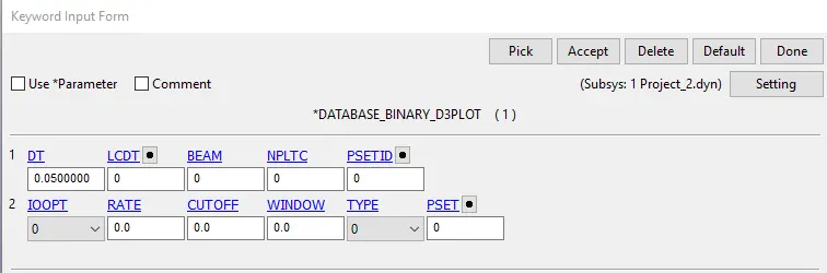
- Keyword manager `rarr`All`rarr` Database`rarr` ASCII_option from which GLSTAT,MATSUM,NODOUt option is selected with DT= 0.05 ms
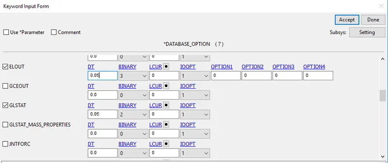
- BINARY_D3PLOT: It defines the frequency at which the animation file is to be created and is set to 0.05
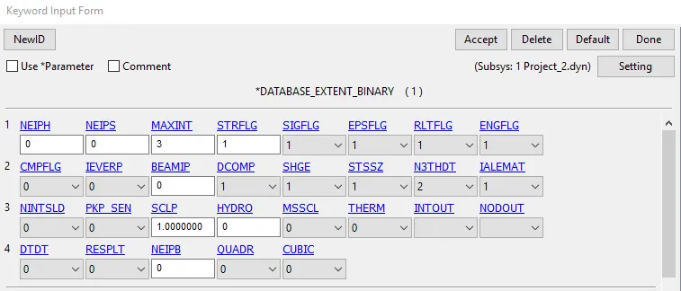
- Keyword Manager `rarr`Database `rarr` Extent_binary with IMFAG = 1 is given , this will compute the elastic strain in the model
9. Run the simulation
- The keyword is saved in a separate folder and it is opened in Ls-Dyna manager
Effective stress:
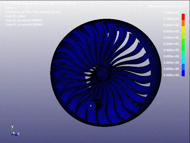
The Maximum stress attained here is 4.884 E-02 kg-mm/`ms^2`
Effective plastic strain:
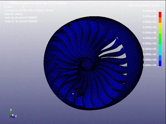
The Maximum strain attained here is 2.723 E-01
Observations:
- Since the thickness of the bird is 5 mm which is greater than that of the blade which is 2 mm. it can be noticed from the simulation that the blade is getting broken down after impacting with the bird due to the impact of bird velocity.
- owing to the imposed displacement given the blade does not stop even after impacting.
Graph:
Energy graph:
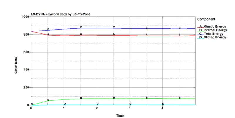
- here we can notice that the impact of bird can be noted in the form of kinetic energy, also the blade deforms correspondingly the internal energy of the system starts acting in the opposite direction to the kinetic energy
- so we can notice that the plot satisfies the law of conservation of energy
- hence the total energy of the system remains constant throuhout the simulation.
Stress and Displacement:
A random element is selected at the point of impact and the stress acting on it is plotted.
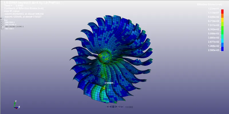
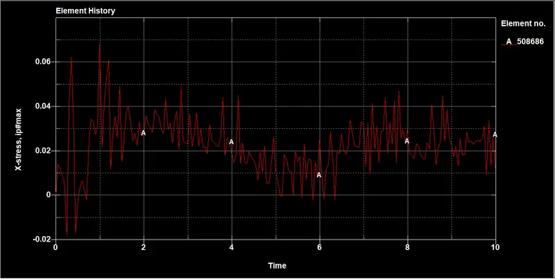
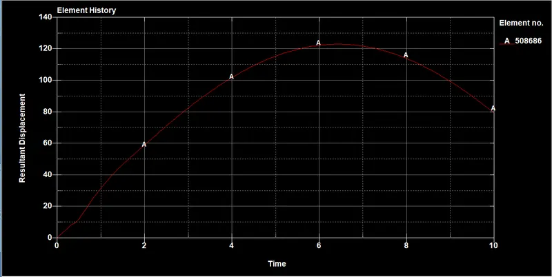
here we can see from the graph the displacement of the element keepon increasing steadily during the impact and as the bird moves away from the from the element the displacemnt is reduced.
Inference:
- In this simulation we have assigned Mat_Elastic for the bird with general properties, hence the simulation obtained from this cannot be compared with real time simulation data.
Conclusion:
Transient-non linear bird strike simulation where the birds hits the gas turbe blades - Using LS-Dyna is performed and the results are plotted.