Bird Strike - Project - 2
AIM:
To simulate a bird strike on an aircraft blade using ls dna explicit solver, which comes under classic nonlinear transient dynamic problem. We call collisions between a bird and aircraft as a “bird-strike events,” and they are quite common and dangerous. According to the Federal Aviation Administration (FAA), wildlife strikes cost the U.S. civil aviation industry over $300 million and more than 500,000 downtime hours each year. Also, people’s lives have been lost or being in risk due to aircraft malfunctions after bird-strikes which make it imperative to design aircraft components capable of withstanding these impacts.
PROCEDURE:
STEP 1:
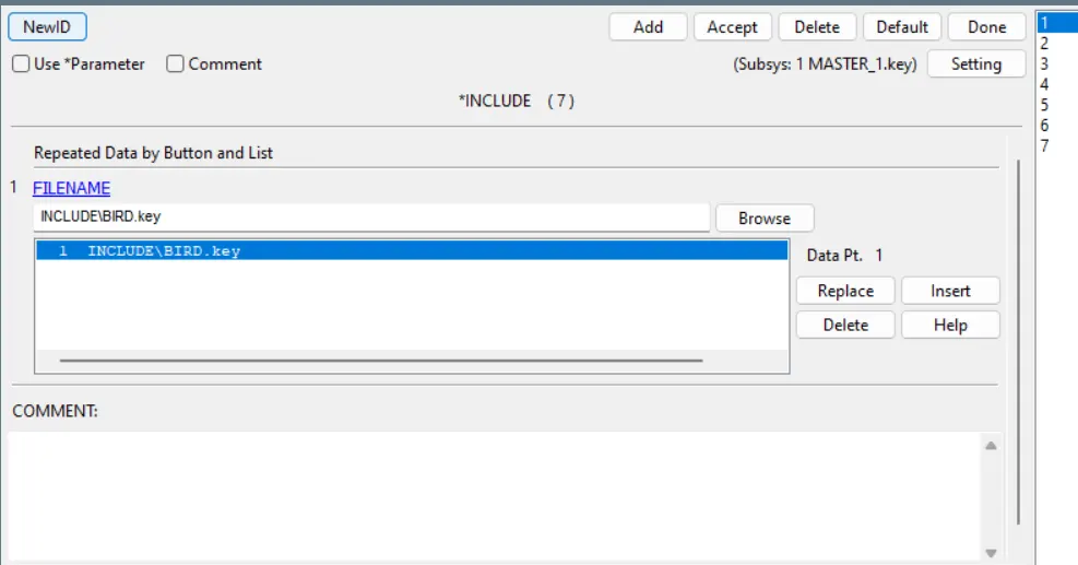
The given file consist of turbine casing, bird, blade and hub. We have to maintain a separate include file for each parts. So open the given file in four different window and kept only one respectively and save it. Now we have each parts in separate files.
STEP 2: Material:
BIRD:
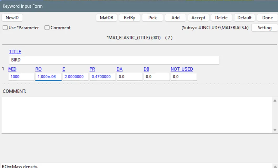
- The standard density of bird model is 936 kg/m3 which is approximately equal to 1.00e-06 kg/mm3
- The youngs modulus of bird model is given as 2GPa which is 2 after the unit conversion to kg/mm/ms.
- The poisson ratio is taken as 0.47 referred from the research paper.
- Use MAT_ELASTIC_001 material card and enter the above mentioned values.
Blade:
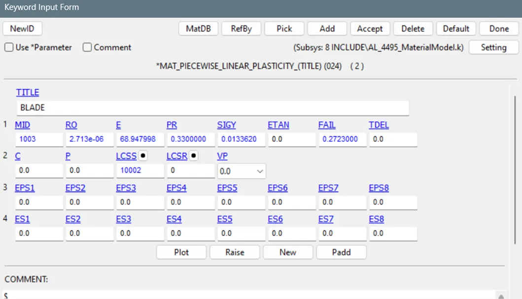
- For blade, a material model is given, that can be used.
Hub:
- The turbine hubs are typically made from cast iron, steel or aluminium etc because it should be highly durable, strong and inextensive.
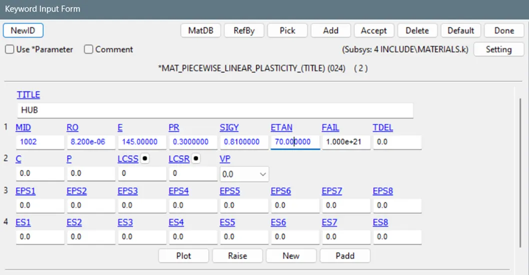
- The density of the hub is 8200 kg/m3 which is 8.2e-6 kg/mm3 after unit conversion.
- Youngs modulus value is 145Gpa and the plasticity region is defined using yield stress and tangent modulus values.
- MAT_PIECEWISE_LINEAR_PLASITICITY_024 material card is used which is used to define the plasticity of the model.
Casing:
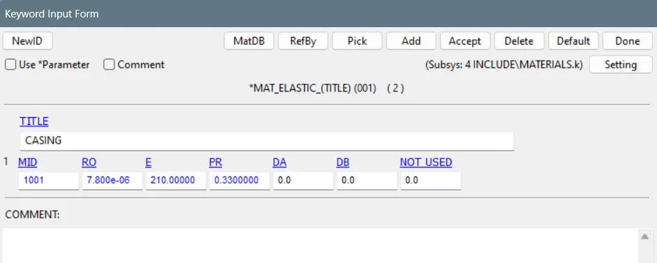
- The default steel material property is used as shown below.
STEP 3: SECTIONS
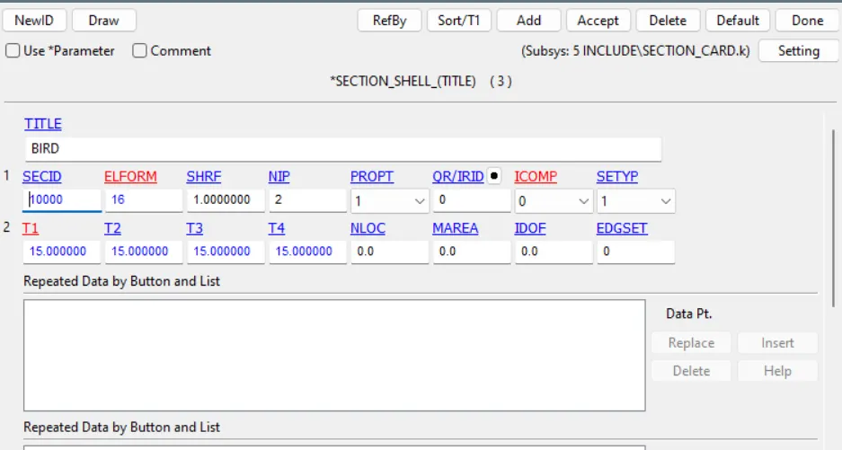
BIRD:
- Since it is an outer mesh model, section_shell card is used.
- Elform value is taken as 16 for highly accurate in simulation with nip value 2(default).
- Thickness is given as 15mm.
Blade:
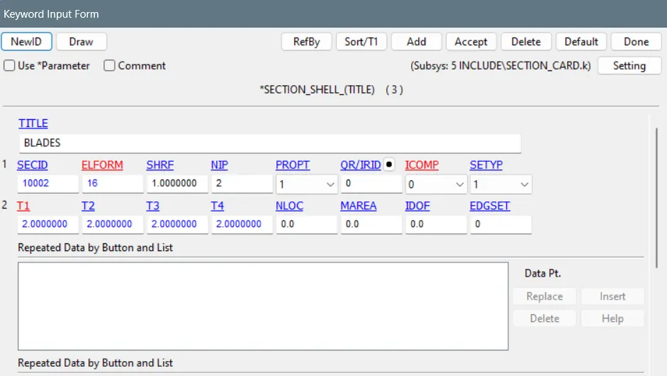
- Section_shell card is used as it is a mid mesh model with thickness 2mm (assumption).
- Elform 16 is used for accurate result and default nip value 2 is used.
CASING:
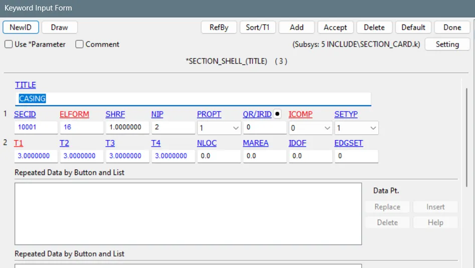
- Section_shell card is used as it is a mid mesh model with thickness 3mm (assumption).
- Elform 16 is used for accurate result and default nip value 2 is used.
Hub:
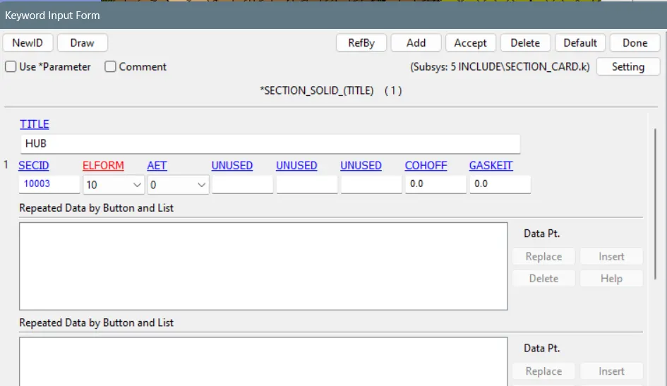
- Hub is modelled as tetra solid mesh.
- For tetrahedron elements, elform 10 should be used.
STEP: 4
- Now include the mesh models (Bird, Blade&hub, Casing), using keywork>include>insert>accept in to the master file.
STEP 5: CONTACT:
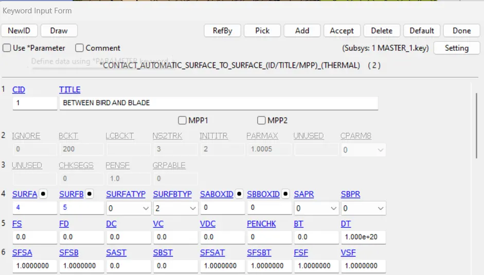
Contact between bird and blade:
- Here bird is more deformable than blade that we can conclude by comparing the young modulus values of both the components.
- Contact_automatic_surface_to_surface card is used.
- Master set is selected as blade and the slave set is selected as bird.
- Select the master set type and slave set type based on what type of set data you are creating.
Contact between blade and casing:
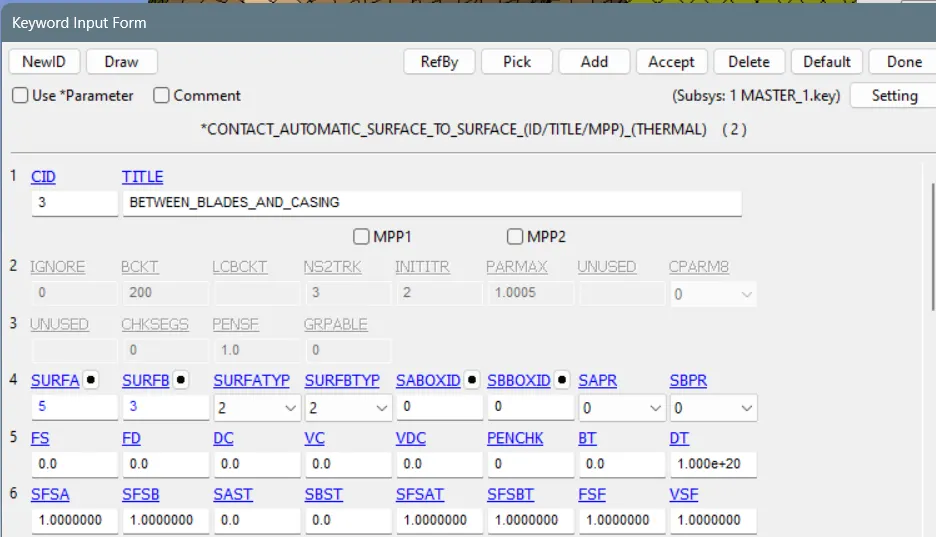
- By comparing the youngs modulus values of blade and casing it is found that blade is more deformable than casing.
- Thus blade is defined as slave set and the casing is defined as master set.
- Contact_automatic_surface_to_surface card is used.
- Select the master set type and slave set type based on what type of set data you are creating.
Contact between blades:
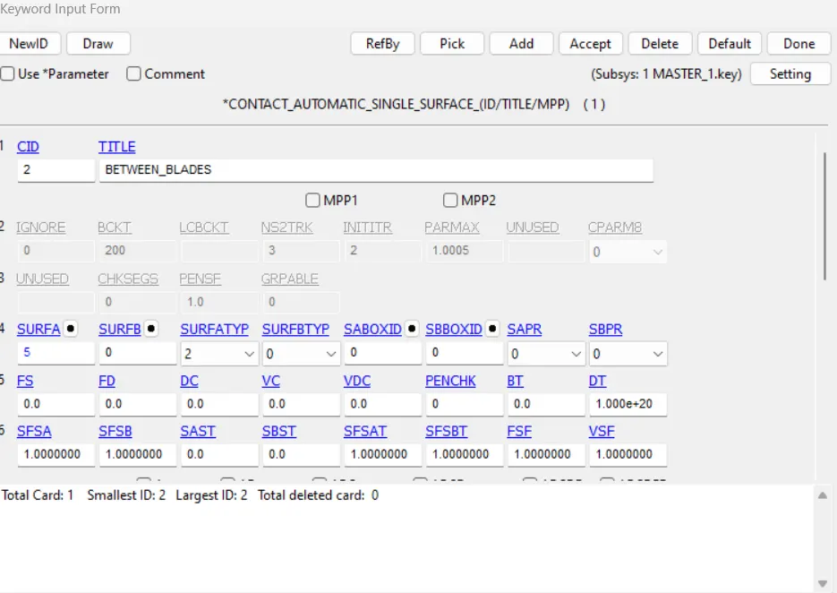
- After colliding with bird, the blade under go rapid deformation. To avoid self penetration between the blades, Automatic single surface contact card is used.
- To define a single surface contact, the slave set is selected as bird and the master set should be kept emply.
Contact between blade and hub:
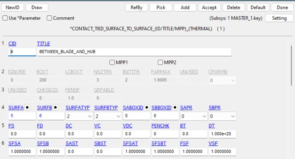
- Tied contact should be given betwwen the blade and the hub so that the blade won't go away from the hub. The balde surface is constrained with hub surface.
STEP:6 BOUNDARY CONDITIONS:
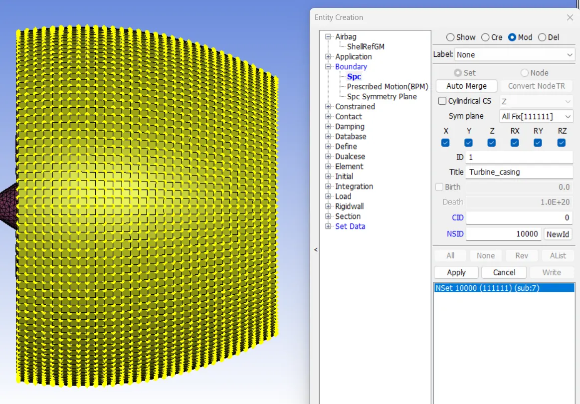
Through out the simulation, the turbine casing should be fixed. As like in the real condition, the turbine casing is attached to the aeroplane wings. Go to model>create entities>boundary>spc_set>select the casing>fix in all dof>apply.
STEP:7 INITIAL_CONDITIONS
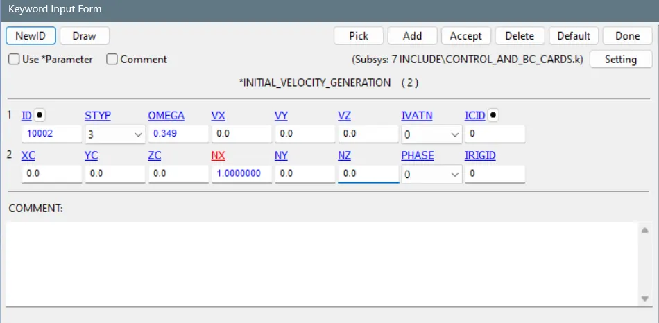
- The speed of the blade is assumed to be 5000rpm, thus the angular velocity is equal to 0.349 rad/ms. The rotational axis is along x direction, so give NX value as 1.00.
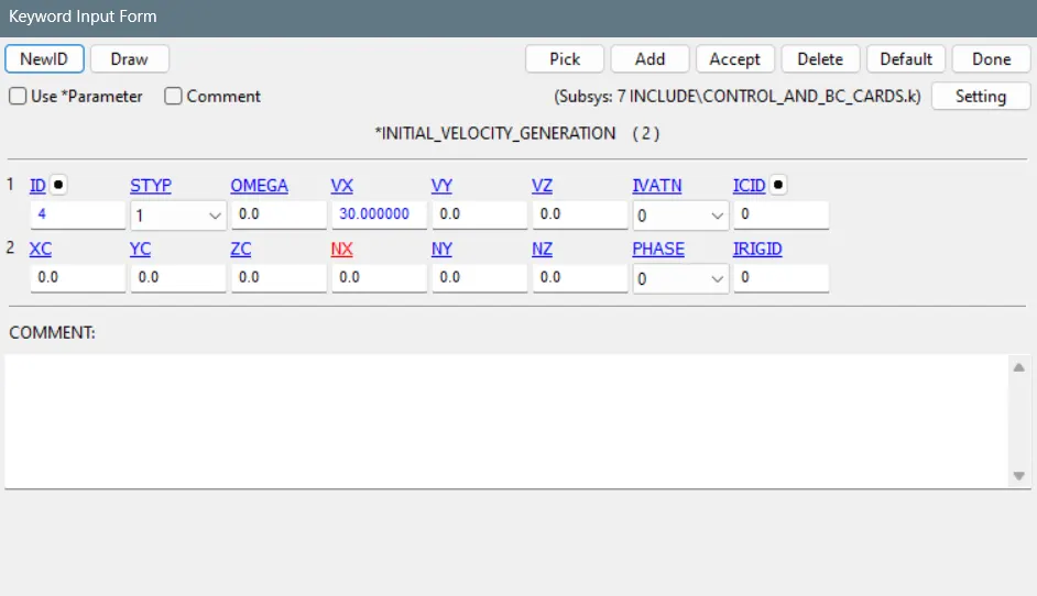
- The average velocity of the bird is assumed to be 30m/s which is 30mm/ms.
STEP 8: CONTROL CARDS:
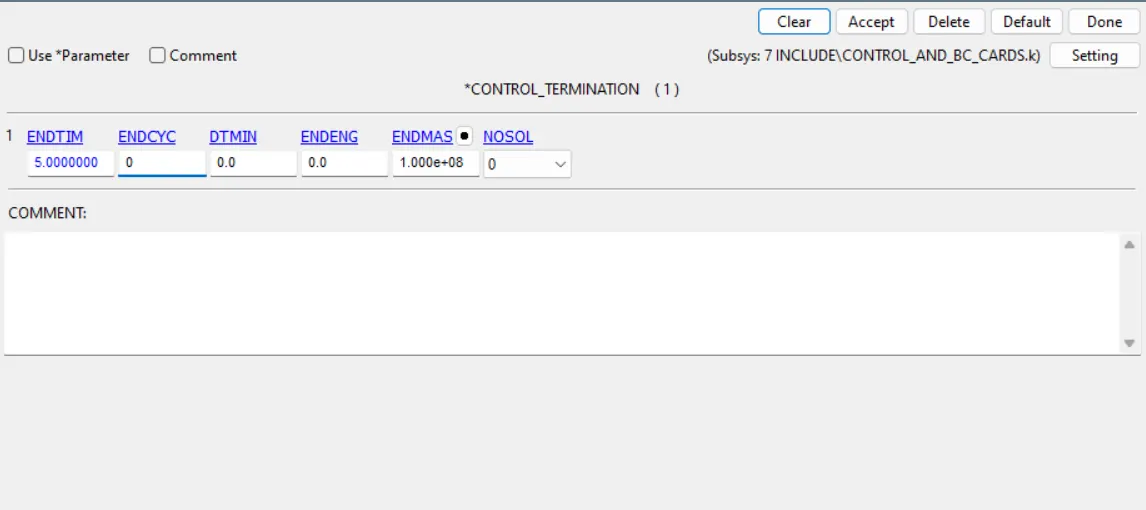
TERMINATION:
- The distance between the bird and the blade is 20 mm and the velocity of the blade is 30mm. The time at which the bird colloides wtih the blade is 0.67 ms. To measure the deformation after collision, the end time of the simulation is given as 5ms.
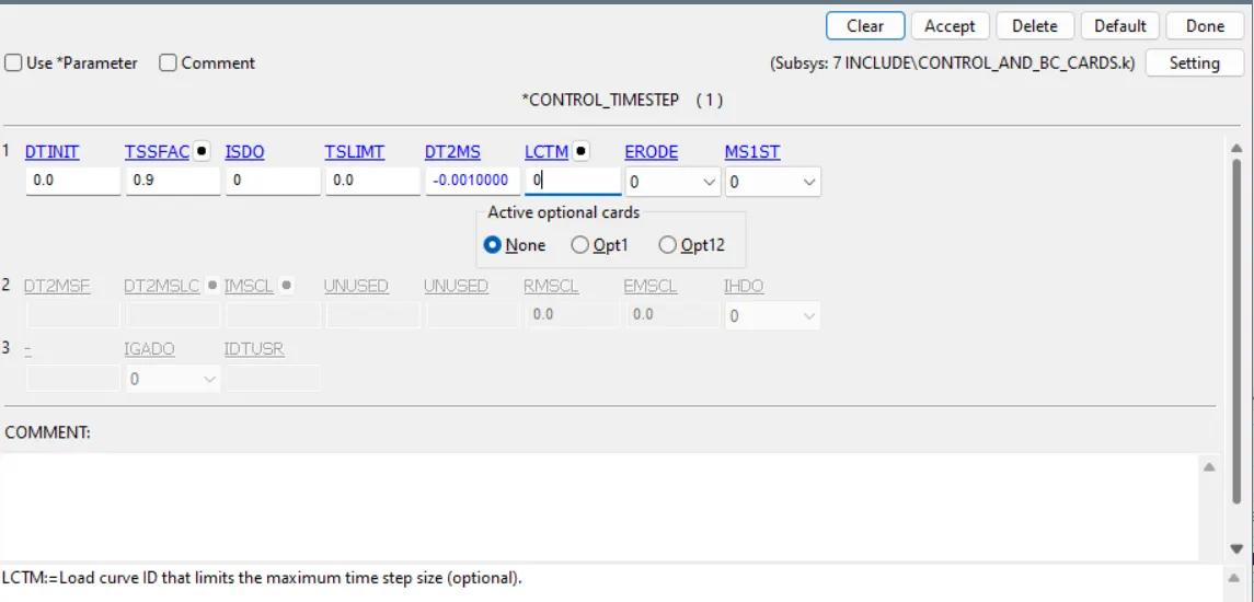
Control_time_step:
- Use trial and error method to calculate the DT2MS value. First enter 1e-5ms and check the percentage increase in mass. Reduce the value until the percentage increase in mass comes to less than 8%.
STEP 9: RENUMBERING:
Now include all the created file into master key file. Go to model>renumber>Enter the start id and click on set and renumber.
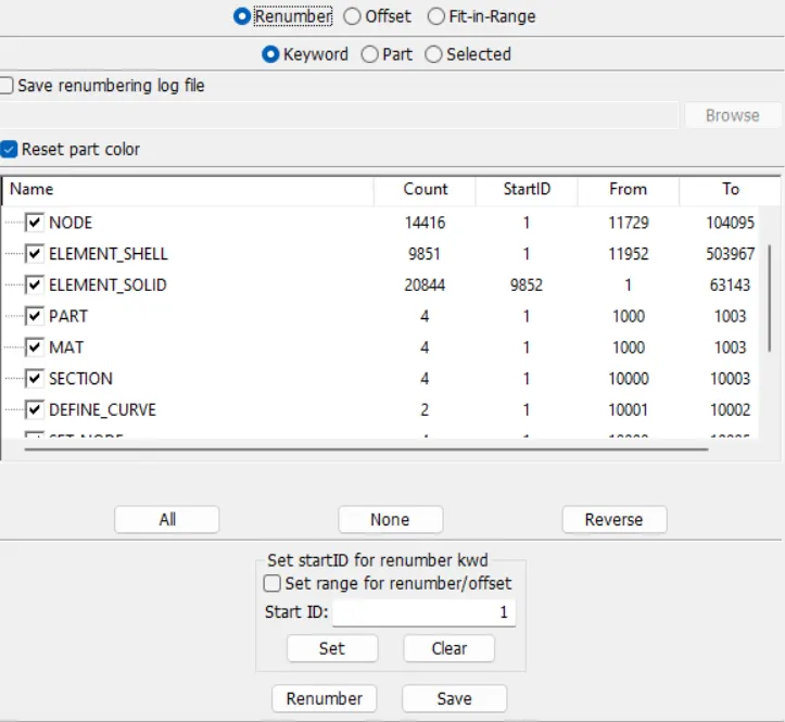
- Node ids should start from 1e+5 and above
- Element ids should start from 5e+5 and above.
- part ids should start from 1000 and above
- Remaining keyword ids should be in a range 1e+04 to 2e+04.
- After renumbering cross check all the keywords.
STEP 10: DATABASE:
- BINARY_D3_PLOT to record the animation of the simuation.
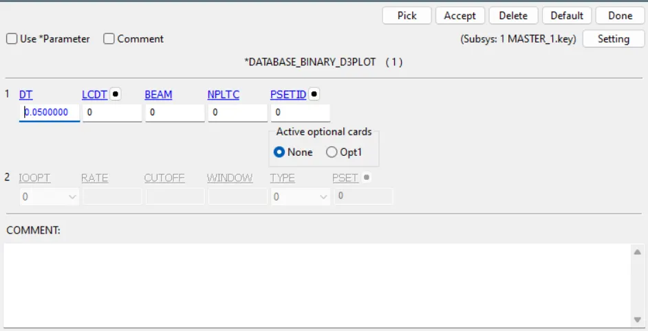
- GLSTAT and RCFORC option are selected in ASCII output.
RESULT:
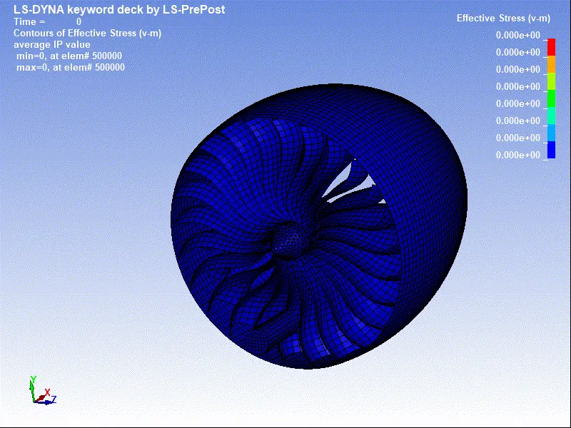
VON MISES STRESS:
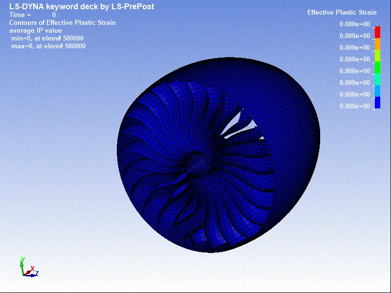
EFFECTIVE PLASTIC STRAIN:
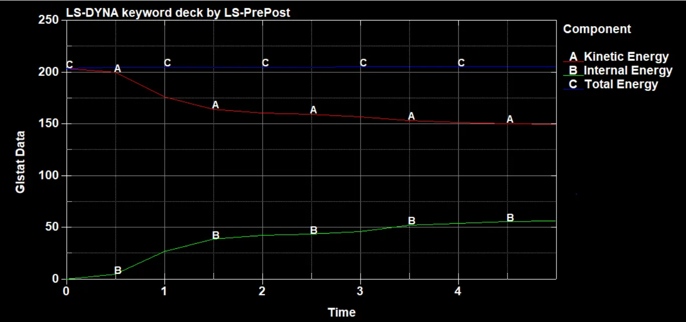
KINETIC ENERGY vs INTERNAL ENERGY vs TOTAL ENERGY CURVE:
RESULTANT DISPLACEMENT IN BLADE:
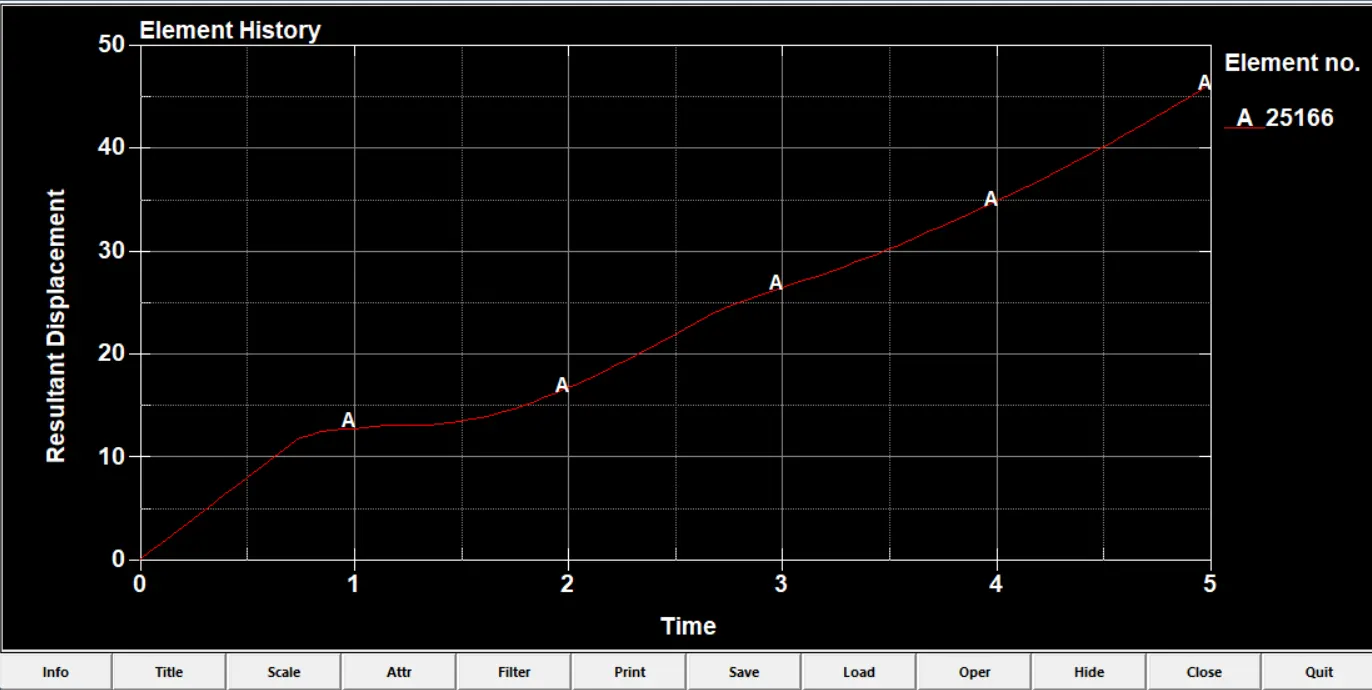
We know that the time bird colloides with the blade is 0.67 ms. Unitl 0.67 ms the displacement curve is linear which means the blade is moving with constant velocity but after collision the velocity of the blade is affected and it is non linear.
Conclusion:
Thus the bird strike on a turbine of the aeroplane engine event has been successfully simulated using lsdyna explicit solver.