Bird Strike - Project - 2
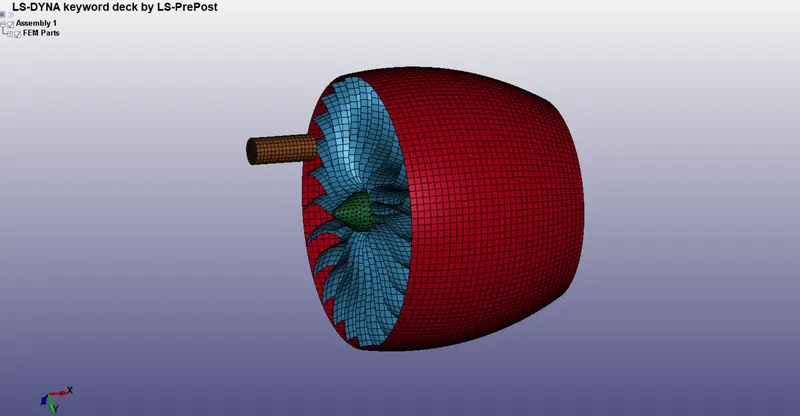
Bird Strike in Aero Engine
Aim:
- Separate the given model to each file according to parts and then run the model using include keywords. The parts (blade, hub, casing & bird), related properties in different files, boundary conditions, and solver deck should be in the main file.
Procedure:
- The first step is to open the given file in the LS-Prepost interface. Initially, all the parts were in a single file so the parts present in the file are separately saved in different files in .k format. The important thing is to choose a proper numbering system as I'll be using an include file later to create an assembly. The numbering should be very consistent and should not repeat. Here are my naming and numbering formats for my deck preparation.
-
NODE ID ELEMENT ID PART ID SECTION ID MAT ID bl_casing.k 10000 100000 8001 2 1003 blade.k 20000 200000 8002 2 1002 hub.k 30000 300000 8003 3 1002 bird.k 4000 40000 8004 2 1004
-
- First, create the part card for the casing. Now delete all other parts from the file. Then create section_Id according to the shell elements present in the casing. Then create the material for the casing and give reference in the part card. Now renumber the remaining node_ID, element_ID, section_ID and mat_ID according to the previous scheme, then save the file differently. The same procedure can be followed to create other files as well. Just the difference is that for the hub the element formulation is different instead of the shell we'll give the solid element formulation.
- The next step is to create a partset including Al_mat.k(which is given in the question statement) blade.k, & hub.k this has been done to make sure both the blade and hub move as one single body. The NSID of the partset is taken as 17000.
- A partset has been created from the create entity in LS-Prepost whose ID is given as 18000. As the partset doesn't have any mat so the given mat card has also been included in the partset file. After creating the partset the partset file looks like below
-
$# LS-DYNA Keyword file created by LS-PrePost(R) V4.7.17 - 08Jul2020
$# Created on Sep-26-2022 (23:33:48)
*KEYWORD
*TITLE
$#                                                                         title
PARTSET
*SET_PART_LIST_TITLE
BLADE_HUB
$#     sid       da1       da2       da3       da4    solver
     18000       0.0       0.0       0.0       0.0MECH
$#    pid1      pid2      pid3      pid4      pid5      pid6      pid7      pid8
      8002      8003         0         0         0         0         0         0
*INCLUDE
$#                                                                      filename
B:Master_ProgramLS-DYNAChallengesProject_2ITR2Includeblade.k
*INCLUDE
$#                                                                      filename
B:Master_ProgramLS-DYNAChallengesProject_2ITR2Includehub.k
*INCLUDE
$#                                                                      filename
B:Master_ProgramLS-DYNAChallengesProject_2ITR2IncludeAl_mat.k
*END
-
- A partset has been created from the create entity in LS-Prepost whose ID is given as 18000. As the partset doesn't have any mat so the given mat card has also been included in the partset file. After creating the partset the partset file looks like below
- The next step is to create the contact cards. There are two types of contacts here. The first one is tied-contact between blade and hub, the next one is for the contact between bird and blade. For contacts, the numbering scheme is chosen to start from 14000.
- Surface to Surface Contact: This contact is defined to capture the contact behaviour of bird and blade. For this contact formulation, the master part is chosen as the blade and the slave part as the bird.
- Tied-Contact: The tied contact is between the blade and the hub so that both the part can move as a rigid body and the motion can be transferred from the hub to the blade. Here the master part is the hub and the slave part is the blade.
- The contact card is given below-
-
$# LS-DYNA Keyword file created by LS-PrePost(R) V4.7.17 - 08Jul2020
$# Created on Sep-26-2022 (14:26:10)
*KEYWORD
*TITLE
$#                                                                         title
CONTACT
*CONTACT_AUTOMATIC_SURFACE_TO_SURFACE_ID
$#     cid                                                                 title
     14000BLADE AND BIRD
$#    ssid      msid     sstyp     mstyp    sboxid    mboxid       spr       mpr
      8004      8002         3         3         0         0         0         0
$#      fs        fd        dc        vc       vdc    penchk        bt        dt
       0.0       0.0       0.0       0.0       0.0         0       0.01.00000E20
$#     sfs       sfm       sst       mst      sfst      sfmt       fsf       vsf
       1.0       1.0       0.0       0.0       1.0       1.0       1.0       1.0
*CONTACT_TIED_NODES_TO_SURFACE_ID
$#     cid                                                                 title
     14001HUB AND BLADE
$#    ssid      msid     sstyp     mstyp    sboxid    mboxid       spr       mpr
      8002      8003         3         3         0         0         0         0
$#      fs        fd        dc        vc       vdc    penchk        bt        dt
       0.0       0.0       0.0       0.0       0.0         0       0.01.00000E20
$#     sfs       sfm       sst       mst      sfst      sfmt       fsf       vsf
       1.0       1.0       0.0       0.0       1.0       1.0       1.0       1.0
*END
-
- The next step is to create the boundary card to include in the main file. For boundary conditions, we are creating two types of boundary conditions which are SPC and Initial velocity.
- SPC: The SPC has been created for casing as it remained constrained. This signifies that the casing is just here for enclosing the blade and not the point of interest in this study.
- Initial Velocity: Initial velocity boundary condition is given to impose the angular velocity on the partset which include both blade and hub part. The angular velocity of the blade and the hub is taken as 0.209 rad/ms. In the same way, the velocity of the bird has also been defined which is in the linear x direction and the value is taken as 28 mm/ms.
- The boundary card is given below-
-
$# LS-DYNA Keyword file created by LS-PrePost(R) V4.7.17 - 08Jul2020
$# Created on Sep-26-2022 (14:36:12)
*KEYWORD
*TITLE
$#                                                                         title
LS-DYNA keyword deck by LS-PrePost
*BOUNDARY_SPC_SET_ID
$#      id                                                               heading
         0SPC_CASING_NSET
$#    nsid       cid      dofx      dofy      dofz     dofrx     dofry     dofrz
     17000         0         0         0         0         0         0         0
*INITIAL_VELOCITY_GENERATION
$#nsid/pid      styp     omega        vx        vy        vz     ivatn      icid
     18000         1     0.209       0.0       0.0       0.0         0         0
$#      xc        yc        zc        nx        ny        nz     phase    irigid
       0.0       0.0       0.0       1.0       0.0       0.0         0         0
      8004         2       0.0      28.0       0.0       0.0         0         0
       0.0       0.0       0.0       0.0       0.0       0.0         0         0
*END
-
- The next step is to define the control cards. In the control card, we've created hourglass, timestep and termination cards.
- In the timestep card, the dtinit is given as 0.01 and the total termination time is taken as 10ms. The control card is given below
-
$# LS-DYNA Keyword file created by LS-PrePost(R) V4.7.17 - 08Jul2020
$# Created on Sep-26-2022 (14:39:45)
*KEYWORD
*TITLE
$#                                                                         title
CONTROL
*CONTROL_HOURGLASS
$#     ihq        qh
         1       0.1
*CONTROL_TERMINATION
$#  endtim    endcyc     dtmin    endeng    endmas     nosol
      10.0         0       0.0       0.01.000000E8         0
*CONTROL_TIMESTEP
$#  dtinit    tssfac      isdo    tslimt     dt2ms      lctm     erode     ms1st
      0.01       0.9         0       0.0-1.7500E-5         0         0         0
$#  dt2msf   dt2mslc     imscl    unused    unused     rmscl    unused      ihdo
       0.0         0         0                           0.0                   0
*END
-
- In the timestep card, the dtinit is given as 0.01 and the total termination time is taken as 10ms. The control card is given below
- Now to assemble all the above files in a single main we've to use the include keyword to create a subsystem assembly. After including everything into one file we've to save and open the file again in LS-Prepost. Here we've to check all the references and run the keyword checker, if any errors are present then we've to work to eliminate the errors. If everything looks good then run the main file in LS-Run and check how it runs or shows error.
- After the assembly, the main file looks like this
-
$# LS-DYNA Keyword file created by LS-PrePost(R) V4.7.17 - 08Jul2020 $# Created on Sep-27-2022 (21:03:58) *KEYWORD_ID Main_v2 *TITLE $# title Main_File *INCLUDE $# filename Includepart_setpart_set.k *INCLUDE $# filename Includebird.k *INCLUDE $# filename Includebl_casing.k *INCLUDE $# filename B:Master_ProgramLS-DYNAChallengesProject_2ITR2Includeb_cond.k *INCLUDE $# filename B:Master_ProgramLS-DYNAChallengesProject_2ITR2Includecontact.k *INCLUDE $# filename B:Master_ProgramLS-DYNAChallengesProject_2ITR2Includeoutput.k *INCLUDE $# filename B:Master_ProgramLS-DYNAChallengesProject_2ITR2Includecontrol.k *END
-
Conclusion
- It took a lot of time to understand the whole process of this challenge. When I started I had little to no knowledge about the includes and assembly of a subsystem. It took about 6 iterations to find out the functionality and nature of include keyword.
- Initially, I've just created the individual part files and saved all the other references in the main file. This file ended up in a fatal error when I opened the main file in ls-prepost. Kishan Jee helped a lot in understanding the functionality of the include keyword.
- In the next iteration, I created a separate file for section and mat cards as well as the other keywords. This also ended up in a fatal error.
- In the next iteration, I reached considerable success. Where my main files were able to read all the sub-system files without any error. Now all the problem remaining was referencing errors. Which were caused by the numbering error. I've revised the numbering system at least 5 times in order to get away with all the errors.
- Finally, my 12th iteration finally worked and ran for almost 5 hours. I've got my simulation results for the first time after 20 days of my start. Still, I'm working on the mass scaling to reduce the run time and doing trial and error iteratively.