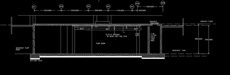
AutoCAD_Layout of Kitchen Cabinet, Elevation of a Residential Building and Industrial Building section_Week 9
Q1)
AIM :
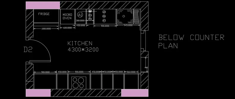
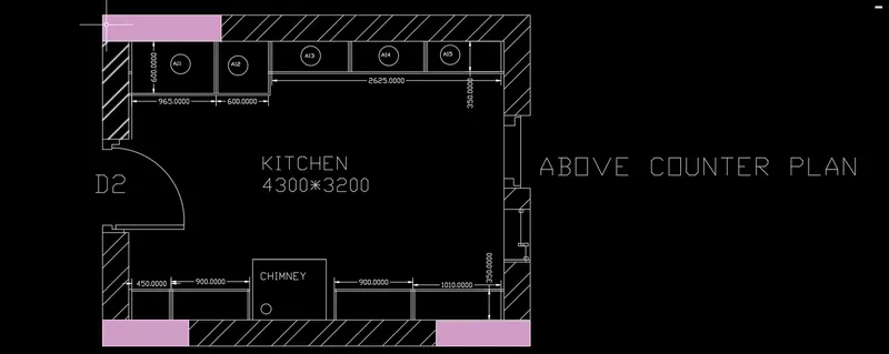
Create the layouts of the Kitchen and provide hatches pattern as shown. Also, use blocks wherever
required. Provide appropriate dimensions in the plan. Assume the size of doors, appliances and others
as per the standards.
PROCEDURE :
open the autocad and press the un enter to invoke units command.
set the units to milimeters and decimal.
invoke the rectangle command by pressing rec enter and enter the values 4300,3200.
take the outer offset of 300 units and leave the space for door D2.
hatch the outer walls by pressing h enter and select the pick point.
from the inner left side of kitchen take the offset of 1000 followed by 600,450
900 and 945 and take small offsets close to their boundaries.and
mark the texts inside them shown in figure and mark the dimensions.
from the bottom left side of kitchen start taking offsets of 900,450,900,450,450,
560 and mark small offsets close to their boundaries.
mark the dimensions and texts, and writein the centre of kitchen as kitchen
in bold letters along with dimension.
Q2)
AIM :
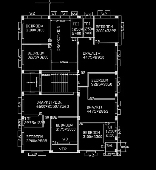
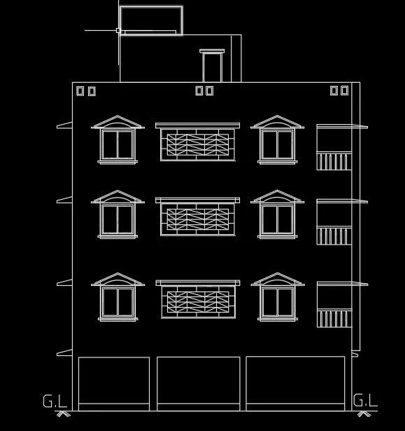
Create the elevation of the plan created in the Challenges 7 and apply proper hatch in the walls, doors,
windows, and other architectural elements. Refer to the dimensions in Plans and sections in Challenges 7.
Refer to the elevation that needed to be created.
PROCEDURE :
for drawing the elevation refer to the figure given in week 7 challenge.
start projecting lines from every corner of it , as shown in figure draw window 2 on the projected lines of it.
there are two windows in the plan and draw an open mesh for veranda as shown in figure.
and draw balcony on the projected lines as well and lintels both the sides.
copy this entire group of windows and mesh ,chajja and place them one above the other as
it is a three storey building.
and draw mumty at the top of roof as shown in figure.
Q3)
AIM :
Create the section view of an industrial building as shown in Figure. Provide appropriate hatches and
dimensions wherever required. Also, provide annotations to the drawing.
PROCEDURE :
open the autocad and press the un enter to invoke units command.
set the units to milimeters and decimal.
invoke the rectangle command and draw a rectangle with some assumed dimension shown in figure.
and draw the wall of 300mm from outer side.
at the top of figure draw a small vertical line and start taking offsets given in the figure and mark its dimensions.
draw three vertical lines at the centre of figure at some regular distances.
entire structure can be drawn easily with the help of line command.
hatch the outside portion and mark the texts.