AutoCAD_Isometric View of a Room, Facade of a building, Staircase and Wall with footing in AutoCAD 3D_Week 12
Q1)
AIM :
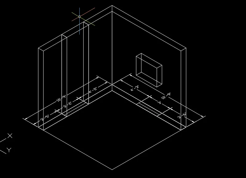
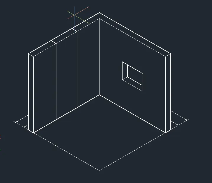
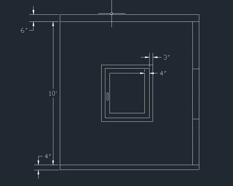
Create a 3D Isometric View of the building with plan and elevation given.
PROCEDURE :
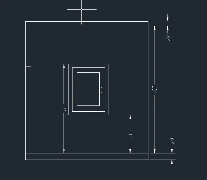
open the autocad and draw the plan as given in the question.
change the viewcube to isometric we will get the inclined plan.
press BO enter i.e boundary command and select pick point.
select the boundary of plan in three separate portions.
invoke the region command by pressing REG enter and select the regions, press enter.
now change the view to shaded from 2d wireframe .
invoke the extrude command by pressing ext enter and extend this lines to make walls .
here we are assuming the wall height as 10ft.
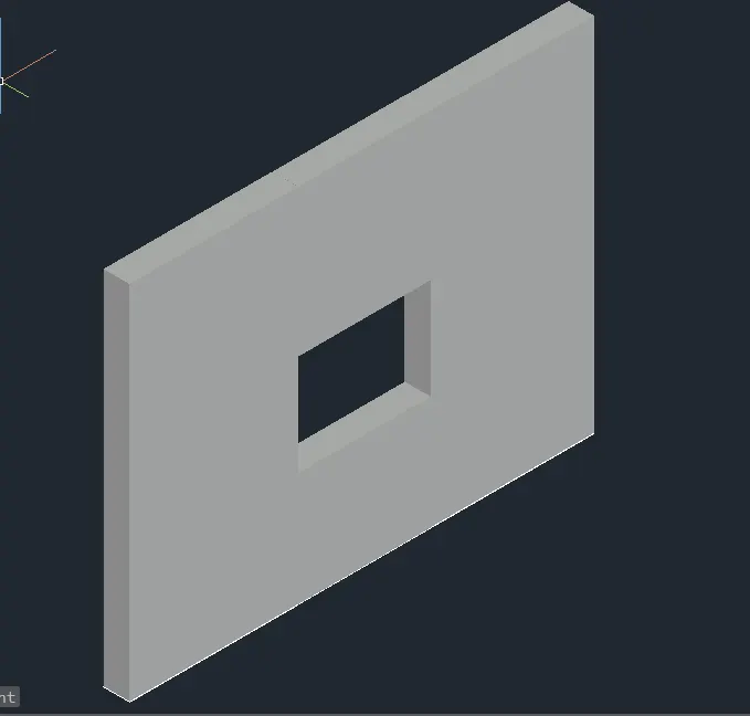
now make a rectangle on the window in the plan and extrude it the same way as we do for walls.
now again change the view to hidden from shaded and invoke the union command by pressing un enter.
and combine the window with the walls to make a single wall.
again change the hidden and invoke the subtract command by pressing sub enter.
and select the extruded walls and press enter, now select the window.
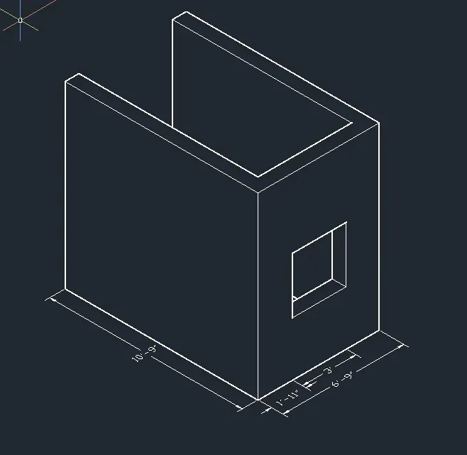
it will be subtracted from the wall leaving a hole for window,mark the dimensions and shade the figure if you want.
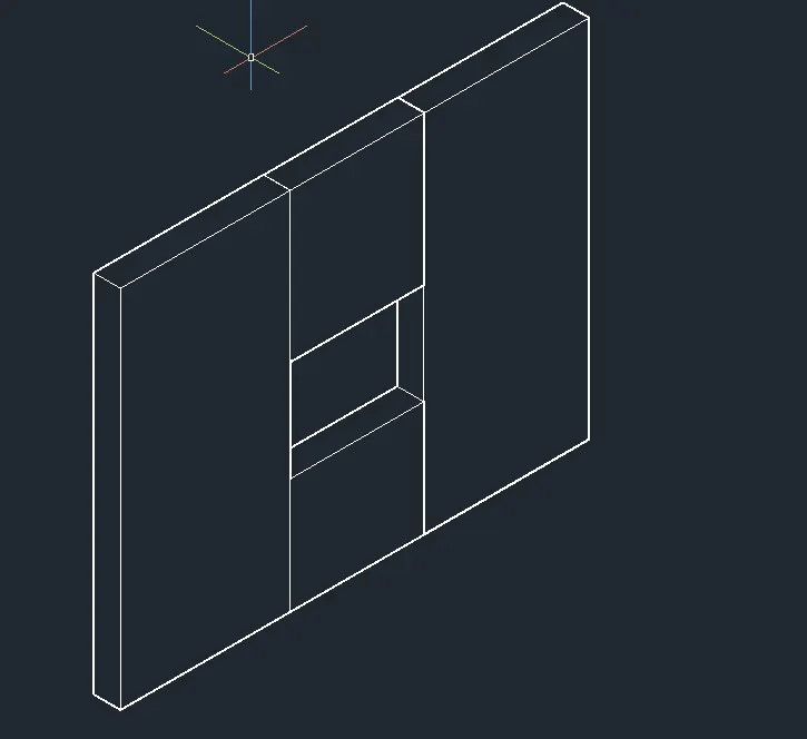
same method is to be followed for the two elevations given in figure.
Q2)
AIM :
Create the 3D View of the Building Façade as given in the plan and elevation. Also, see the detail of
the window.
PROCEDURE :
open the autocad and draw the plan as given in the question.
change the viewcube to isometric we will get the inclined plan.
press BO enter i.e boundary command and select pick point.
select the boundary of plan in three separate portions.
invoke the region command by pressing REG enter and select the regions, press enter.
now change the view to shaded from 2d wireframe .
invoke the extrude command by pressing ext enter and extend this lines to make walls .
here we are assuming the wall height as 10ft.
now make a rectangle on the window in the plan and extrude it the same way as we do for walls.
now again change the view to hidden from shaded and invoke the union command by pressing un enter.
and combine the window with the walls to make a single wall.
again change the hidden and invoke the subtract command by pressing sub enter.
and select the extruded walls and press enter, now select the window.
it will be subtracted from the wall leaving a hole for window,mark the dimensions and shade the figure if you want.
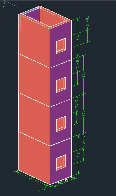
to draw the elevation in 3d take this 3d view of plan ,copy and place them one above the other and shade the portions.
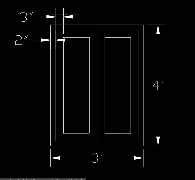
details of the window are shown at the end.
Q3)
AIM :
Create the ismoteric 3d view of a stair with railing as shown in the plan and elevation. Assume the
size of the balustrades and the hand rails.
PROCEDURE :
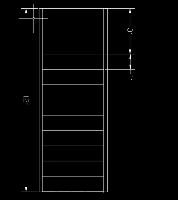
open the autocad and draw the plan of staircase as shown in figure.
draw a vertical line of 12 feet width of stair is assumed and take the offset of 3ft for landing,
followed by an offset of ft which shows the tread and width of handrail is also assumed.
draw the cross section of stair as shwon in figure and move the viewcube to isloated.
press the reg command and select the entire staircase .
invoke the extrude command by pressing ext enter and extrude the staircase .
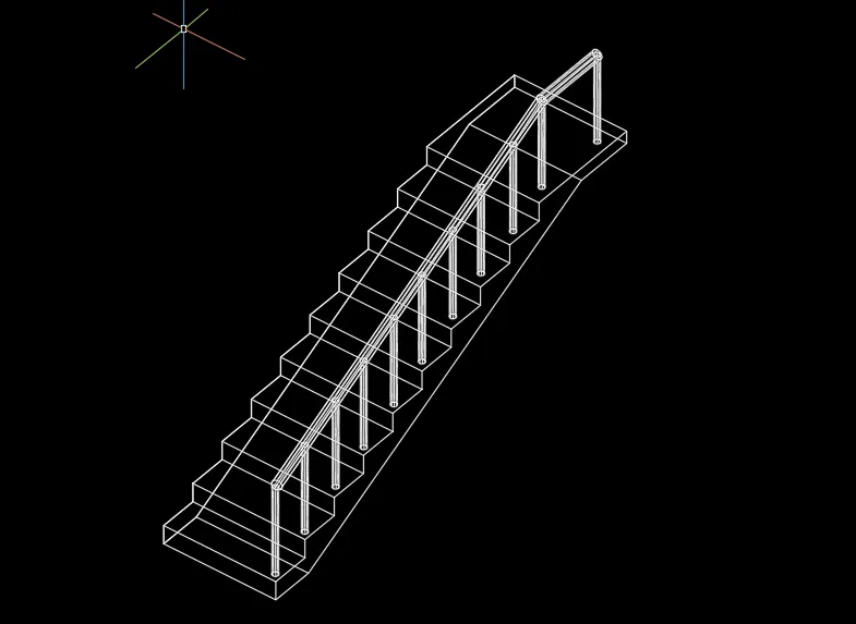
draw a small circle on any one tread and raise it with the help of extrude command, copy it and place at every tread to
draw the hand rail, connect the top of these rails with the help of polyline .
draw a small circle ,invoke the sweep command , and select the circle,followed by path
and make a hand rail ,shade it rotate it in any direction you want with the help of 3do command.
Q4)
AIM :
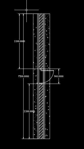
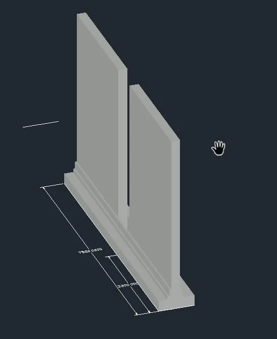
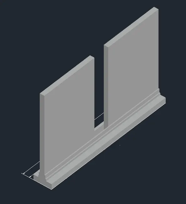
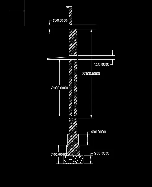
Create the 3D view of a Wall with spread footing . Create the Door opening only. Assume the size of
the parpaet and the coping. See the plans and elevation for the details. Also, create a rendered view of
the model with materials as of your choice.
PROCEDURE :
open the autocad and draw the plan as shown in figure,hatch it properly, leave the space for door.
change the viewcube to isometric we will get the inclined plan.
press BO enter i.e boundary command and select pick point.
select the boundary of plan in three separate portions.
invoke the region command by pressing REG enter and select the regions, press enter.
now change the view to shaded from 2d wireframe .
invoke the extrude command by pressing ext enter and extend this lines to make walls .
here we are assuming the wall height as 10ft.
now again change the view to hidden from shaded and invoke the union command by pressing un enter.
extrude the first second and third steps of stepped footing at height of 600,400 and 400.
change the view to shaded and with the help of 3do rotate it any direction.