AutoCAD_Developing Architectural and Structural drawing_Project 1
AIM :
Design and Draft a layout of a residential building with the following details:
a. Plot Size: 60’x20’(18.3m x6m)
b. Orientation- Facing East
c. Develop the following: 1. Architectural Drawing (Floor Plan, Elevations, and Sections) 2. Structural Drawing (Column, Bean, Footing Plan)
PROCEDURE :
open the autocad and invoke units command by pressing UN command and set the units to feet.
change the settings to decimal and precision 0'0''.
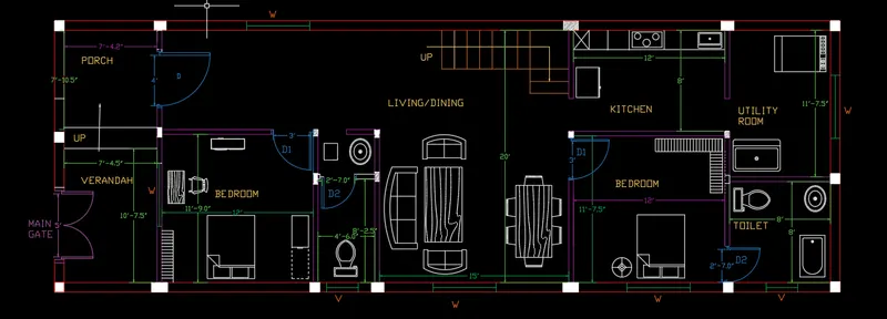
we have to draw a plan of 60'*20'.
with the help of xl command ,draw a horizontal line and vertical line to mark the boundary of plan.
take the outer offset of 9inches to both the walls ,repeat the same procedure on the other side, a plan of 60'*20 is ready.
from the right hand side of the plan ,take an offset of 8' from the inner wall vertically.
take the horizontal offset of 11'7.5 , followed by an offset of 4.5 from the vertical side.
we are naming these rooms as utlity room and toilet, for toilet take the offset of 2'7 vertically to leave the space for door.
for drawing the door, just draw a vertical hinge of 1.5 followed by a horizontal line of 2'7 which marks the length of door.
and from the starting point of door, draw a circle of 2'7 and trim the unnecessary portion, this is done to show the inner opening of door.
placing the room components is done with the help of dc command, just drag them and place where you want to.
from the outer boundary of toilet take an offset of 12' followed by an offset of 4.5, and take a horizontal offset of 8', followed by an offset of 4.5.
here door for kitchen is not provided, a door of 3' is provided to the bedroom, procedure for drawing door is already mentioned.
then take a vertical offset of 15' followed by an offset of 4.5, for the same wall take an offset of 4'6 followed by an offset of 4.5.
take an offset of 8'2.5 from the bottom and leave the space for door.
from the previous wall take an offset of 11'9 followed by an offset of 4.5 and leave the space for door and draw the door.
extend this previous wall upward touching the upper wall and leave the space for main door.
staircase is provided in the hall with two flights .
from the main gate take the offset of 7'4.5 followed by an offset of 9 inches for drawing porch and veranda.
leave the space of 5' for main gate and draw the main gate.
mark the dimensions and texts and complete the plan.
ELEVATION :
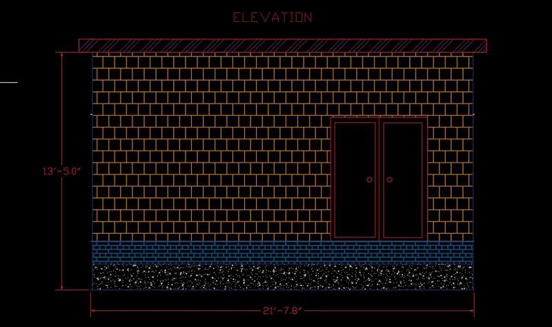
for drawing the elevation project the vertical lines from the front face of plan.
in this plan start projecting the vertical lines .
draw a horizontal line which marks the starting of plinth level.
normally we take the first offset of 600mm followed for plinth level followed by 900mm for sill level.
then 2200 mm for lintel level and 3200mm for roof level.
convert it into feet and take the offsets ,on the elevation we get the vertical lines of door
considering these vertical lines draw the door, mark the boundaries and complete the figure.
hatch the obtained portions of elevation such as front wall ,door, plinth beam.
SECTION :
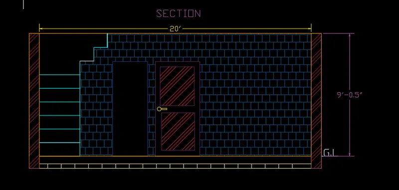
for drawing the section we are cutting the plan vertically from the hall.
what all we can see in the front is staircase , opening for kitchen ,door for bedroom and the two cutted outer walls.
draw it projecting the lines and hatch the portions such as walls, doors staircase and mark the dimensions.
STRUCTURAL DRAWING FOR COLUMN :
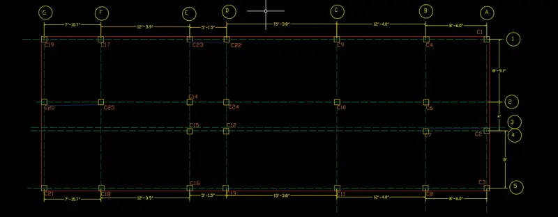
for drawing the column plan just copy the portion of plan where we all had placed columns.
label the columns and mark its distances from one other , all columns provided in this figure are of 9''*9''.
draw the dotted lines vertically and horizontally passing through the columns.
label these lines outside the plan with the help of alphabets and numbers.
STRUCTURAL DRAWING FOR BEAM :
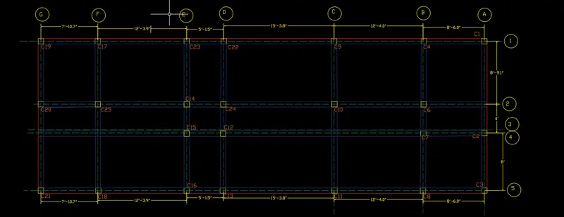
for drawing the beam plan just connect the columns obtained in the previous plan ,
connect them horizontally and vertically.
it shows the upper beam plan. mark the dimensions.
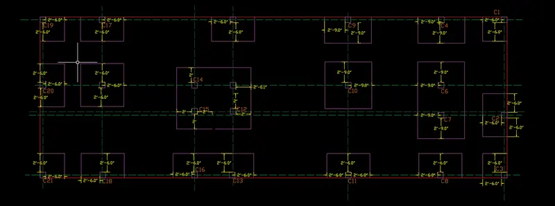
STRUCTURAL DRAWING FOR FOOTING PLAN :
in this figure, to draw the footing plan we are taking offsets of 2'6 from both the sides of columnn.
take the offset from all the three sides for the intermediate columns, combined footing is provided to the four columns at
the centre since they are closely spaced ,mark its dimensions.