AutoCAD_Detailing of Wardrobe, Floor Plan, Kitchen Layout and Column Details_Week 6
QUESTION 1 :
AIM :
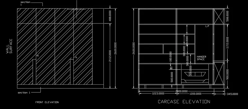
Draw the elevation and details of a wardrobe as shown in the Figure below. After sketching, you need to provide the dimensions and text with the use of layers. Use proper text styles and dimension methods to document it. Also, assume dimensions, wherever needed.
Note: All dimensions are in mm.
PROCEDURE :
open the autocad, first of all set the units to mm by pressing UN command.
set the units to mm and select the decimal option.
to draw the wardrobe given in figure, for front elevation just draw the rectangle of
assumed dimension and ,and from the top line take an offset of 488units followed
an offset of 2112 units ,draw a horizontal line at some assumed height just to show the stand
of wardrobe.
hatch the inside portion of wardrobe by pressing h enter command, pick point and depending upon the
thickness required ,hatch the portion,draw small circles at the mid of it which shows the
holder to open or close the wardrobe.
mark the dimensions and label the wardrobe with texts.
to draw the carcase elevation,draw a rectangle of dimensions given infigure and take the offsets
from outside with some assumed dimensions, from the inner top horizontal line take an offset of 508
by pressing o enter command,followed by an offsets of 300 units 3 times one after the other,
all the designs shown in the figure at right top and right bottom can be drawn easily with the help of line command.
draw small vertical lines at the bottom of figure at equal spacing which shows the stand of wardrobe.
mark the dimensions and texts.
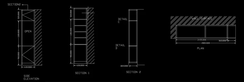
side elevations and plans can be drawn easily looking at the figure, with the help of line command,
mark the dimensions and use texts to label them and complete the figure.
QUESTION 3:
AIM :
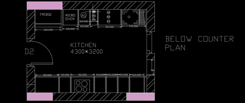
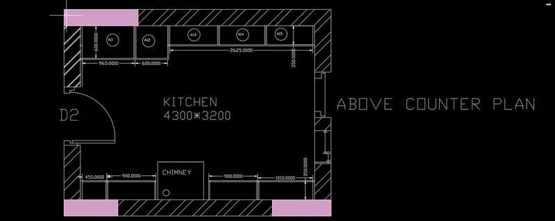
Create the Kitchen Layout as shown in the Figure below. Also, use proper dimension techniques to dimension the kitchen layout. Also, insert text wherever required. All dimensions are in mm.
PROCEDURE :
open the autocad, first of all set the units to mm by pressing UN command.
set the units to mm and select the decimal option.
press the xl command and draw the horizontal and vertical lines to mark the lower corner of kitchen,
take an offset of 300 units to mark the outer boundary of kitchen,from the inner horizontal line ,take an offset of 600 .
now start taking offsets from left vertical sides of 900 followed by 450, 900, 450, 50,50, 560.
and draw the vertical lines from each of their corner, repeat the same on the top side according to the dimensions
enter the texts in the components of the kitchen.
mark the dimensions and complete the figure.
QUESTION 5 :
AIM :
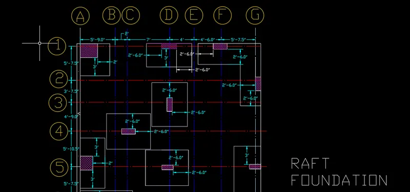
Draw the Raft Layout as shown in the Figure. Assume the column size as per your knowledge. You can take the sizes as: 24”x24”, 9” x 24”, 9” x 18”, and 9’ x 24”. You can import the raft_foundation.pdf to ensure the missing dimensions.
PROCEDURE :
open the autocad, first of all set the units to mm by pressing UN command.
select the locus line from the line ribbon provided at top right of interface.
draw a vertical line and take offsets of 5'9 followed by 2', 7', 4', 4'6, 5'7.5 .
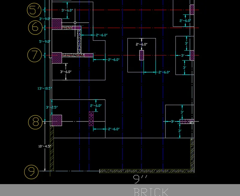
from the same point draw a horizontal line and start taking offsets of 5'7.5 ,3'7.5, 4'9 ,5'10.5, 5'7.5,3'9, 5'9,
13'10.5, 10'4.5 .
dimensions of the columns are not given so ,their dimensions can be assumed.
in the first column provided at the middle top, take an offset of 2'6 from the left side and right side and 3' at the bottom.
repeat the same procedure to mark the footings of columns throughout the figure.
mark the dimensions throughout the figure along with texts.
QUESTION 2 :
AIM :
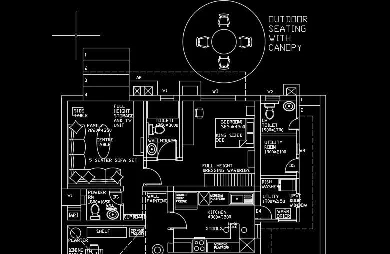
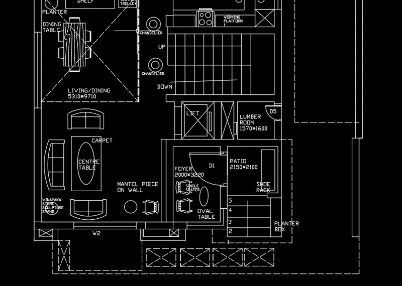
Draw the floor plan as shown in the Figure. Use the proper drafting tools to sketch the plan. Do not hatch or draw the furniture. You need to draw the floor plan with the following:
Note: You can also import the Floor_Plan.pdf into your current drawing and start working on the project. You need to scale the imported pdf file using reference option. All dimensions are in mm.
- Walls (Exterior and Interior)
Wall Thickness: Exterior Wall- 230mm, Interior Wall: 150 mm (Wherever Required)
- Doors and Windows: Assume the size of the doors and window.
2.1 Stairs: Tread-300mm, Riser-150mm
- Insert Text wherever required
- Insert the dimensions using proper dimension techniques
PROCEDURE :
open the autocad and enter the xl command and draw horizontal and vertical lines .
take the offset of 300mm from outside, lets start from bottom, take an offset of 5310 in the vertical and 9710 in the horizontal ,and mark their respective
boundaries by taking offsets according to their wall thickness,
we get the right boundary of living hall and from that wall take the offset of2000 in the vertical and 3220 in the horizontal.
furnitures mentioned in the living hall can be imported using dc command, in that command,select the option house plan.
and drag the required component to the screen.
canopy is provided at the top ,draw it with the help of circle command, and import the seats using dc command.
for the left top room , take the offset of 3880 at horizontal and 4350 in the vertical, leave the space for door as it is mentioned to be assumed.
take the offset of 150 from the previous wall followed by an offset of 1350 in the horizontal and 3000 in the vertical ,then draw the door with the help of line command.
from the previous line take the offset of 3830 in the horizontal and 4500 in the vertical to mark the boundary of bedroom,furnitures can be imported using dc command.
beside bedroom there is dh toilet ,take the offset of 1900 in the horizontal and 1700 in the vertical and mark its boundary using an offset of 150mm, then draw its door.
there is utility room at its bottom, as the vertical side is already drawn ,just draw the horizontal using offset of 2100 and an offset of 150mm at the bottom.
there is another utility room at its bottom whose dimensions are 1900*2150.
now coming to the kitchen, take an offset of 4300 in the horizontal and 3200 in the vertical, some of its components can be assumed and
some can be imported using dc command,draw the circles which represents stools, sink with the help of line disgram.
now coming to the lumber room whose dimensions are 1570*1600, then draw its door.
other portions such as patio and foyer can be drawn easily, after completing the figure write the accurate texts and complete the figure.
QUESTION 4:
AIM :
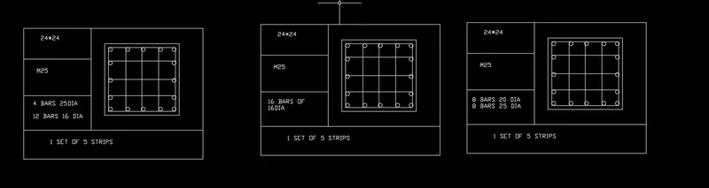
Sketch the column details as shown in Figure. Insert dimensions and text in the figure. Refer to the bar sizes from the schedule.
8mm ---- 0.31 Inches
25mm--- 1 inches
16mm—0.62 inches
PROCEDURE :
open the autocad ,set the units to inches by UN command.
draw a square of 24*24 and draw equal offsets from centre on either sides .
place circles at all the corners which represents the rods.
and make a box and write the texts as given in figure.