AutoCAD_Creating 3d Models_Week 11
Q1)
AIM :
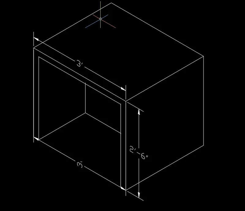
Create a 3D Furniture element as shown in the Figure. Assume dimensions which are missing.
PROCEDURE :
open the autocad ,and chanage the view cube to home in order to get 3d figure.
invoke the line command by pressing l enter and draw a vertical line of 2'6 ,
followed by line of 3 feet in the next horizontal direction and another line of 2'6 at the bottom.
draw another line adjacent to this 3 group of three lines at distance of 2inches.
extend these lines in the backward direction and complete the cube ,
mark the dimensions.
Q2)
AIM :
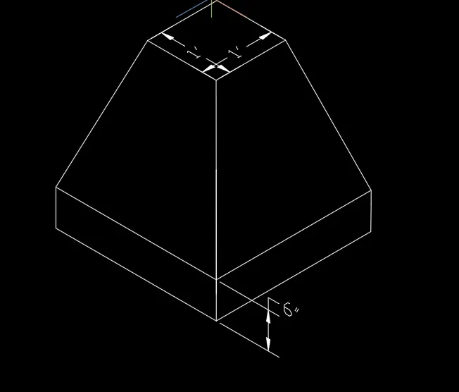
Create the 3d Model of an Isolated footing as shown in Figure.
PROCEDURE :
open the autocad ,and chanage the view cube to home in order to get 3d figure.
draw rectangle of assumed dimensions as shown in figure.
place another rectangle of same dimensions as distance 6 inches above this rectangle.
draw a rectangle of 1'*1' and place it above these rectangles at some distance.
join the lines from all four sides forming a pyramid.
Q3)
AIM :
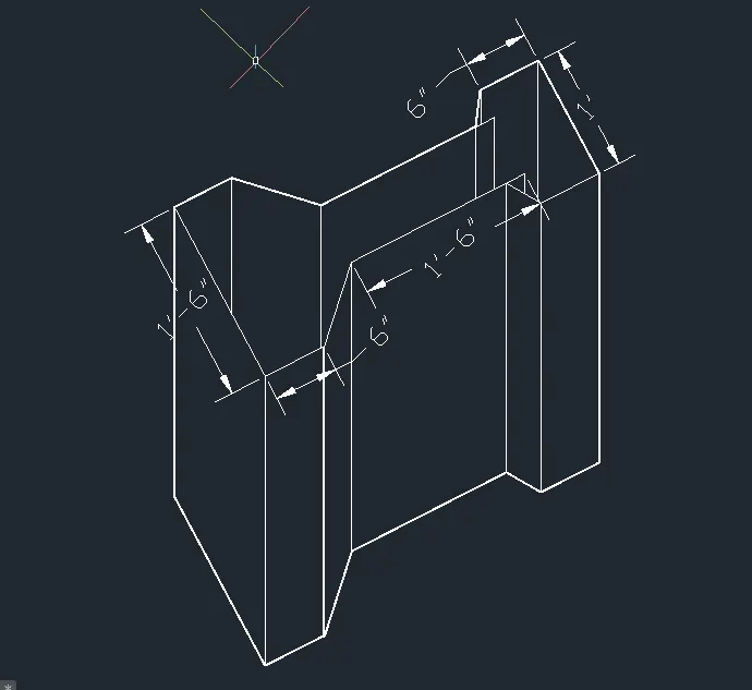
Create the 3D view of the AASTHO Type Girder.
PROCEDURE :
open the autocad ,and change the view cube to home in order to get 3d figure.
with the help of line command draw a rectangle of 1'*6'
and draw lines of 1'6 at the bottom of it connecting diagonals with the previous rectangle.
at the bottom draw a rectangle of 1'6*6''.
draw diagonals from both the sides connecting the lines at centre.
then press the ext command and extrude it at distance of 10'.
mark the dimensions.
Q4)
AIM :
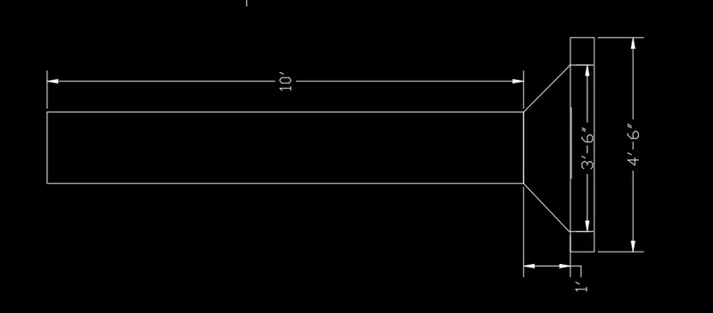
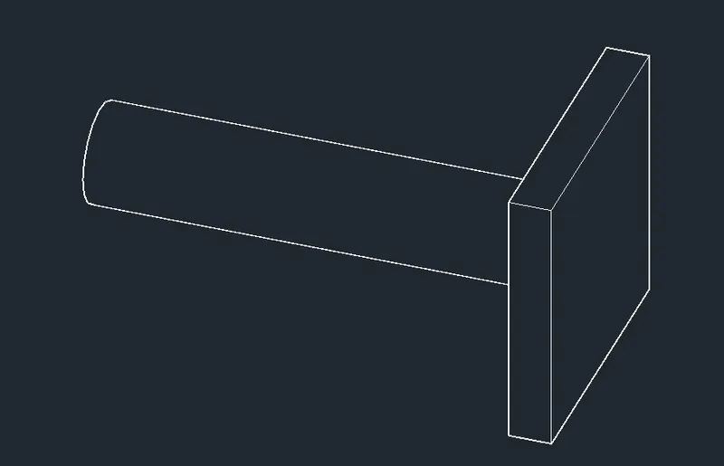
Create a 3d Model of a drop column with panel as shown in section and isometric view.
PROCEDURE :
open the autocad ,and change the view cube to top view in order to get this figure.
invoke the rectangle command and draw a rectangle of 1''*4'6.
mark a centre of this line and take the offset of 1'8 both the sides forming a centre line of 3'6.
draw another rectangle of 10'*1'6 and keep it parallel to the previous rectangle and draw two corner diagonals
from it connecting its ends, and mark the dimensions.
PROCEDURE :
open the autocad ,and change the view cube to home in order to get 3d figure.
with the help of box command in the ribbon draw a box as shown in figure.
to one of its face draw a circle with the help of c enter command.
invoke the extrude command by pressing ext enter and drag it to the place you want.
in order to view it properly change the view to hidden from 2d wireframe.
to get the exact view we can make use of 3do command to rotate in 3d.
Q5)
AIM :
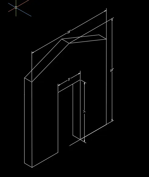
Create the 3d model of a wall as shown in Figure. Consider wall thickness as 9”.
PROCEDURE :
open the autocad ,and change the view cube to home in order to get 3d figure.
presss l enter and invoke the line command and draw a vertical line of 7' followed by 3' and again a vertical line
of 7'followed by a horizontal line of 3.5'.
at the begining of figure draw another horizontal line of 3.5'.
from the centre of figure draw a vertical line of 12' to get the vertical centre.
and draw a vertical lines of 10' either sides joining this vertical centre.
to get the thickness of 9'' draw a horizontal line at every corner and join these lines.
mark the dimensions.