Aston Martin ONE-77 Challenge-11 (Project) Final Assembly
ASTON MARTIN ONE-77
OBJECTIVE
- To set up the blueprints for Aston Martin ONE-77
- To model the individual parts of the Aston Martin ONE-77 using SolidWorks.
- To assemble all the parts with proper mates.
- To give proper appearances and decals for the parts.
- To position the assembly and set up cameras, lights and environments.
- To create photorealistic renders using SolidWorks Visualize.
Aston Martin One- 77 is a sports car built by British car manufacturer Aston Martin. It was built in 2008 but revealed in full at the 2009 Geneva Motor Show.
Specifications:- Body Style :-2 Door Couple
Class :- Sports car
Layout :- Front Engine ,Rear Wheel Drive
Engine :- 7.3L AM Cosworth V12
Power Output :- 559KW
No of cylinder :- 12
Max Torque :- 570Nm
Fuel Tank Capacity :-98.0
Transmission Type :- Automatic
Wheel Base :- 2,791mm
Width :- 2,204mm
Length :- 4,601mm
Height :-1,222mm
The Aston Martin One 77 is a two-door, two-seater flagship sports car built by the British car manufacturer Aston Martin. The Aston Martin One 77 is 4601 mm in length, 2204 mm wide including the wing mirrors and stands at an overall height of 1222 mm. The wheelbase of the car is 2791 mm and has a front track of 1706 mm and rear track is 1627 mm.
INTRODUCTION
SolidWorks is a solid modeling computer-aided design (CAD) and computer-aided engineering (CAE) application published by Dassault Systèmes. It has other ADD-in features like photoview360 which helps in rendering modelS to make it look photo realistic. In this project we learnt about detailed design of Americal chopper parts and assemblig them and rendering the final after assembly.
Solidworks CAD modeling software is used in the following industries: Aerospace & Defense, Architecture, Engineering and Construction, Consumer goods - distribution, FMCG - Distribution, Energy, and processes, Finance and Corporate Services, High Technology, Industrial Equipment, Life Sciences, Marine & Offshore, Natural Resources, and Transport & mobility.
Solidworks enables the creation of 3D parts from 2D sketches, surfacing, sheet metal, weldments, molded tooling parts up to the definition of mechanical assemblies.
DESIGN METHODOLOGY
Modeling of a car is a big task and is done by step by step surface modeling of different surfaces.The car has a symmetric shape, and hence we will be modeling half of the car only and then mirror the body. It will reduce our lot of time. As said earlier, first we have built basic profiles of the car and later on created separate parts for our ease.When modeling a car, the roof is often taken as a starting point, as its construction is quite easy and uses curves spanning the entire model. Hence, we started modeling of the roof first.For modeling roof, projected curves are used to create precise 3D profiles for further surface creation using Surface Boundary tool.For creation of projected curves we need to create sketches first. These sketches were made with the use of splines with their proper dimensioning.
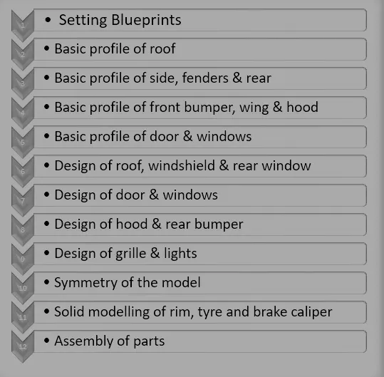
SOLIDWORKS TOOLS AND FEATURES USED TO Aston Martin ONE-77
Fixing SKETCH for start any modeling:
2D TOOLS include in sketch are
- Line
- Circle
- Arc
- Spline
- Rectangle
- Circular Pattern
- Polygon
- Offset
- Fillet
- Mirror
- Ellipse
- Chamfer
- etc
(Each tool have their own unique uses also have contained more options)
Then using FEATURES we can change 2D sketch to any required 3D model objects and any desired item
- Blocks: We can save, edit and insert blocks from the drawing items and sketch entities that you use often such as standard notes, title blocks, label positions and so on you can attach blocks to geometry or to drawing views.
- Boss Extrude: Feature used for expand the object in 3D according to sketch plane.
- Revolve boss base: Feature is used to make cylindrical or circular 3D extrude along with a given reference axis as per drawn sketch.
- Extrude Cut: Extrude cut feature used to cut/remove the 3d object in linear path according to sketch.
- Revolve cut: Revolve cut is used to cut or reduce the extrude of cylindrical round surface.
- Lofted Boss/Base: Lofted boss is a feature used to achieve Complex Shapes. It does this by interpolating surfaces between various cross-sections of a model. These cross-sections can be sketches, faces, or edges.
- Sweep: This feature is used to sweep any kind of fully defined sketch along with the path.
- Sweep cut: Sweep cut is same as sweep feature but its directly proportional to sweep which makes a cut along with the sweep path.
- Linear Pattern: The linear parent is used to create a different number of instances required to create the pattern linearly.
- Circular pattern: Circular pattern is a feature used to make 3d feature into circular pattern according to number of insistences.
- Swept Surface: It is used to make a surface along with a path the curve is driven.
- Boundary Surface: Boundary surface is used to make a surface in between two finished surfaces.
- Curve Driven Pattern: Curve driven pattern is used to make any pattern which followed by the curve is sketched before.
- Curve Driven Pattern: Curve driven pattern is used to make any pattern which followed by the curve is sketched before.
- Loft Surface: Loft surface is used to make loft in between two profiles along with guide path.
- Knit surface: Knit surface is used to knit the two free edges or open edges of the surfaces together also it reduces the gap between the two edges of the surface.
- Move/copy body: This feature is used to move/copy the 3D body to one place to another place.
- Surface Trim: Primarily used to cut away material from a surface, and provides two modes: Standard and Mutual.
- Mirror: Mirror is used to mirror a feature or body by reference of the selected plane.
- Fillet: Fillet is a feature used for making round internal or external edges to avoid sharp edges and make it smooth.
- Chamfer: Chamfer is used to make a sharp edge or corner slightly tapered rather than being a perfect square.
- Split: Split tool is used to split single solid part into two solid parts. It is used to project an entity onto other surfaces or curved/planar faces.
- Dome: Dome is a feature used to make dome shaped extrude including elliptical dome.
- Shell: Shell feature is used to make to hollow space in solid part by selecting outer wall of the solid part and so removes the inner parts. It is also used to reduce the specific thickness.
- Combine: Combine tool is used to make integration of two solid parts which intersect each other as same solid part.
- Projection Curve: Projection curve is a 3D curve which is projected on the basis of the two different 2D curves in two different planes.
- Trim entities: it is used to trim the unwanted lines or extended entities in the sketch.
- Appearances: An appearance defines visual properties of the model including colour and texture. Appearances do not affect physical properties which are defined by materials. every material is a assigned a default appearance.
Sketch Entities:
- Line, circle, rectangle, arc, slot, spline.
- Convert entities- Create one or more curves in a sketch by projecting an edge, loop, face, curve or set of sketch curves on to the sketch plane.
- Trim and extend- cut the point over the sketch entity and move the point over the sketch entity to extend.
- Offset-offset line arc and splines if the original entity change the offset entity also change.
- Mirror- mirroring is another way that can create copy of an existing object choosing a plane or mirror face.
- Pattern- create multiple instances of one are more features that can space alone with pattern type.
Solid features:
- Boss Extrude = It is converting 2D sketch into 3D feature
- Cut extrude = cut extrude is similar to boss extrude but the difference it is cutting the 3D feature
- Sweep = Sweep features are defined by using custom 2D cross-section (or face) moved along a pre-set path to create a 3D shape or surface.
- Loft-Loft feature creates a shape by making transitions between multiple profile and guide curves. this tool is very valuable for modelling complex surface
- Revolve = Revolves add or remove material by revolving one or more profiles around a centreline.
- Shell =The shell tool hollows out a part, leaves open the faces you select, and creates thin-walled features on the remaining faces.
- Mirror = mirroring is another way that can create copy of an existing object choosing a plane or mirror face
Surface feature:
- Surface extrude = Using the Surface Extrude feature, it can extrude the boundary edges of a face or edges of a surface body in a customized direction.
- Surface trim = Create two or more surfaces that intersect at one or more points, or create a surface that intersects with a plane or has a sketch on its face.
- Thicken = Thicken takes a surface body (which has zero thickness) and makes it a solid by specifying a thickness value and side to thicken.
- Surface Trim: Trims a surface when it intersects with another surface, plane or sketch.
- Boundary surface: Creates a surface between profiles that can be tangent or curvature that is continuous in all directions.
- Swept surface: Creates a surface by sweeping sketch along the guide curve.
- Surface loft: Creates a lofted surface between two profiles or sketches.
- Surface knit: Creates two or more adjacent surfaces into single surface.
- Extrude Surface: Extrude a sketch in one or two direction to create a surface feature.
- Filled surface: patches a surface within boundary defined by edges, sketches or curve.
- Offset surface: Creates an offset surface using gaps.
- Ruled surface: Inserts ruled surfaces in a specified directions from edges.
- Delete faces: Delete faces from surface bodies or solid body.
- Extend Surface: Extend one or more edges or faces on surface, based on end conditions and extension type.
- Split line: Projects a sketch on planner or curved face, creates multiple separate sketches.
Common feature:
- Plane - Plane is reference for sketching and creating features.
- Curves - Curve as the path or guide curve for a sweep and loft feature, as a parting line for a draft feature.
- Dome - It creates a dome that is tangent to the adjacent cylindrical or conical face.
- Fillet - Create a rounded internal or external face on the part. selected faces, edges or edge loops.
- Split-use the split feature to create multiple parts from an existing part.
- Combine - Multiple bodies contained within one multibody part file.
- Split line - Tool projects an entity (sketch, solid, surface, face, plane, or surface spline) to surfaces, or curved or planar faces.
APPROACH
- Blueprint
- Roof
- Side
- Rear Bumper
- Front Bumper
- Hood
- Window
- Door
- Front Wing
- Roof Finishing
- Side Door Design
- Hood graphics
- Grills
- Light
- Wheels
- Disc Brake
- Emblem
Blueprint:
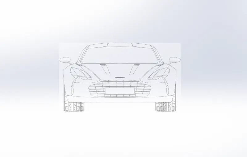
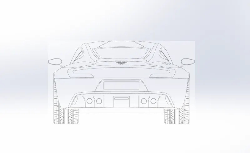
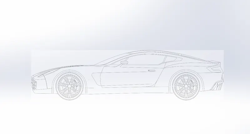
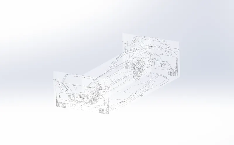
There are three different views (Front Side & Top) used in the Blueprint Setup. By using The Sketch Picture option, the images are inserted and the required dimensions are given to the images.
views:

Isometric:
2.Roof:
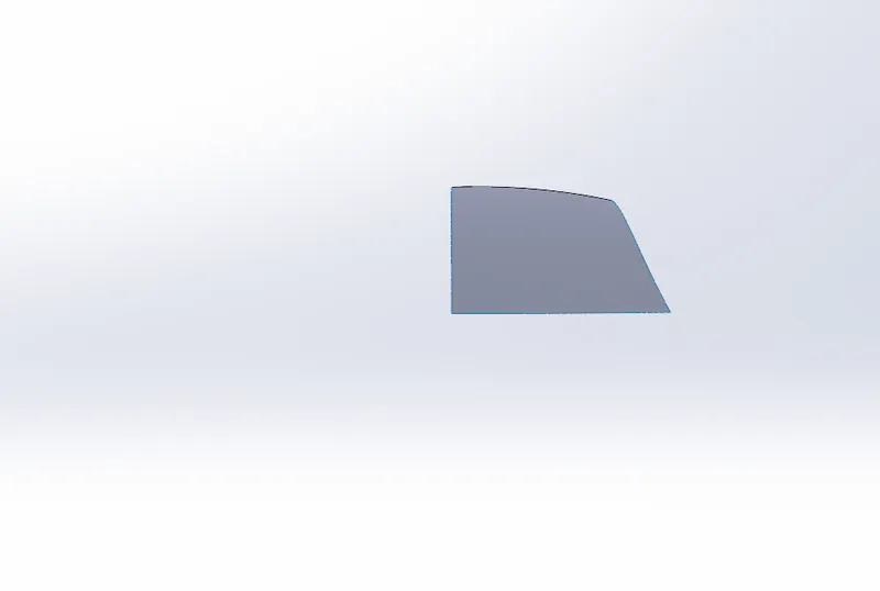
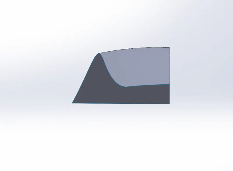
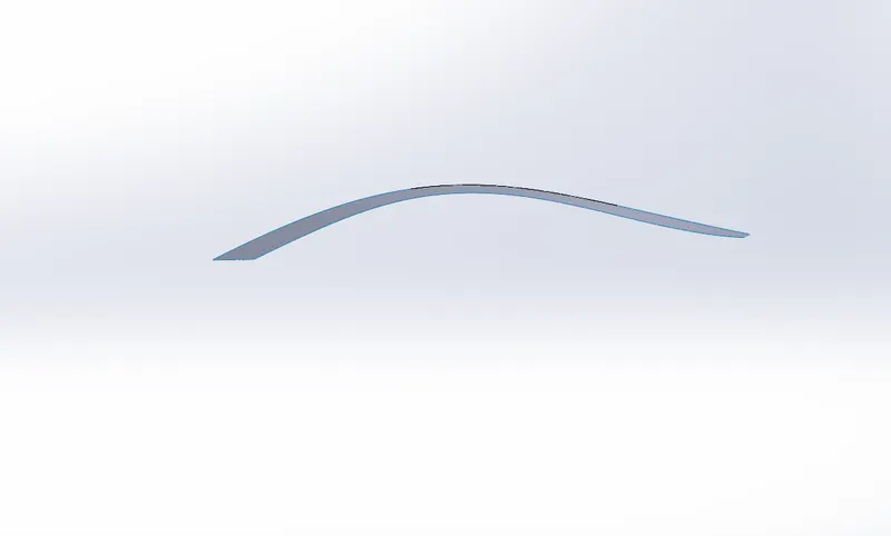
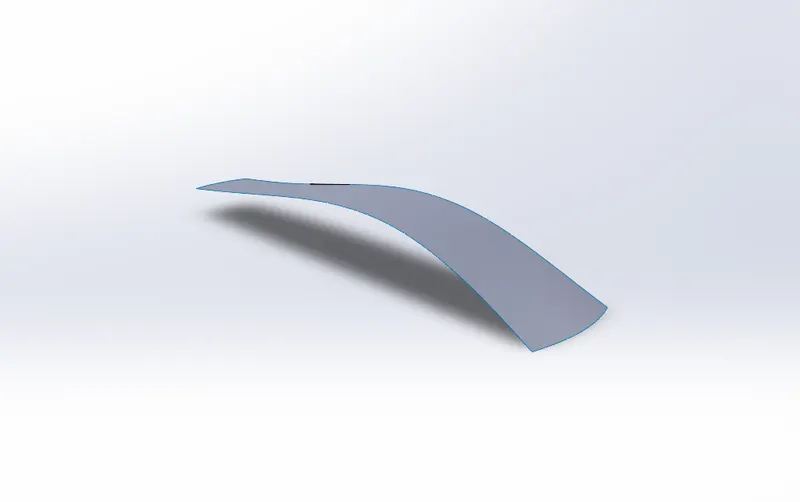
Start a sketch on top plane and dimensioned properly,Start a sketch on the side plane and dimensioned properly basically here we have to draw a projected curve to apply surface boundary surface tool .
Views:
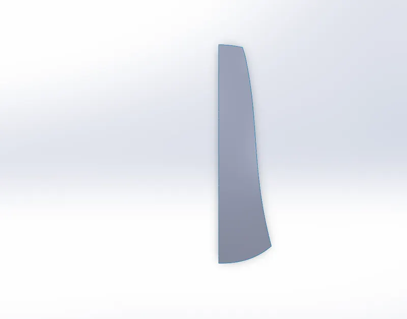
Isometric:
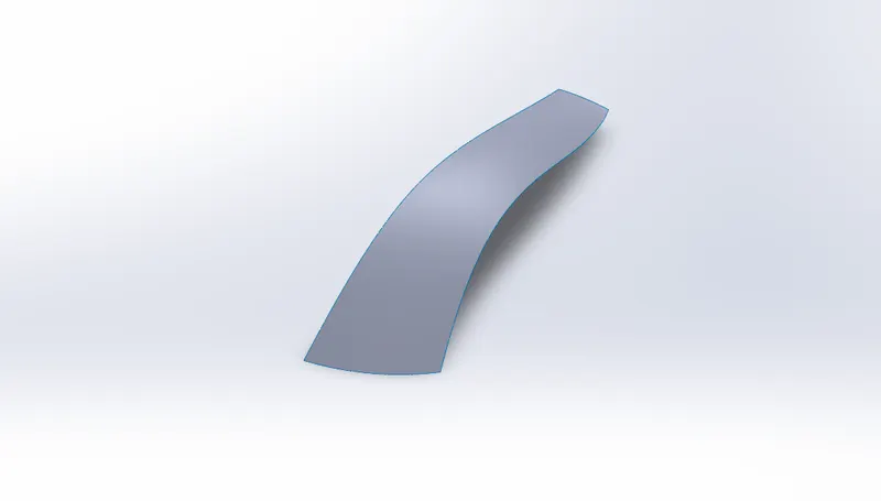
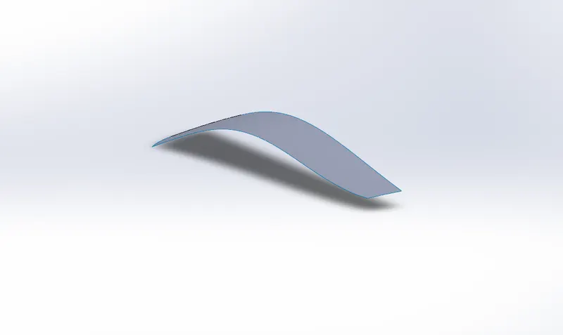
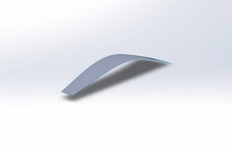
Side:
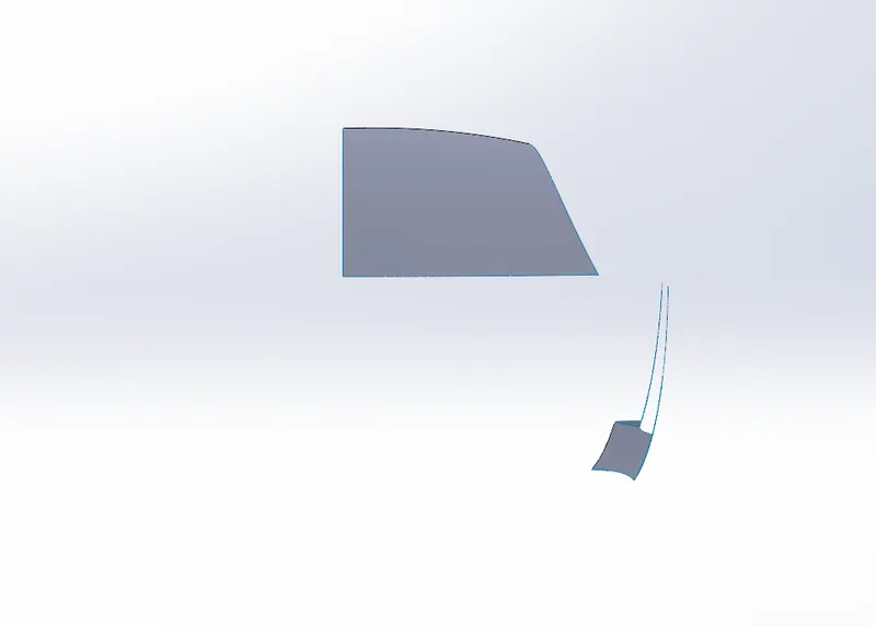
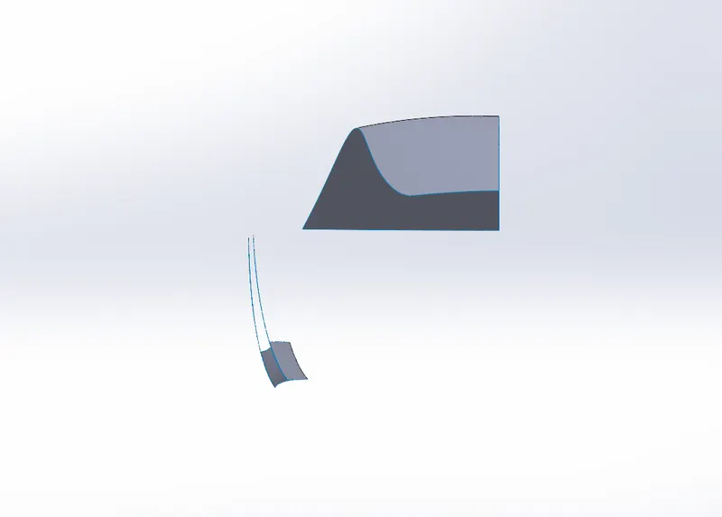
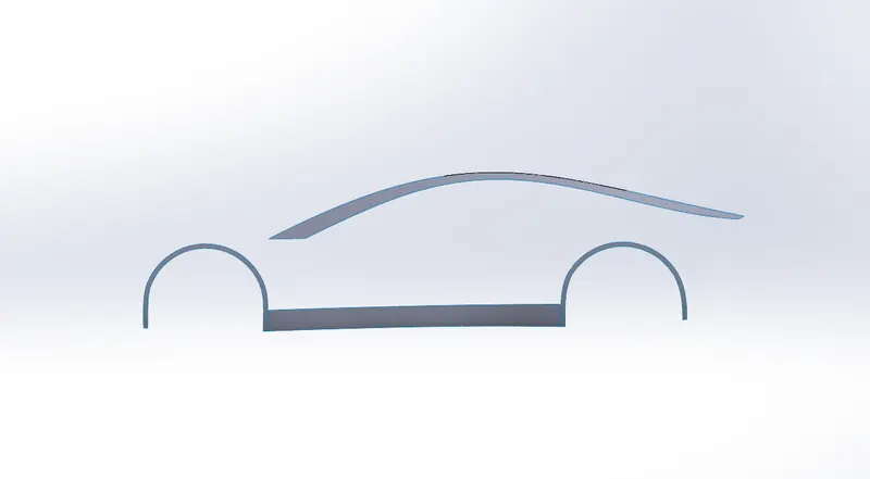
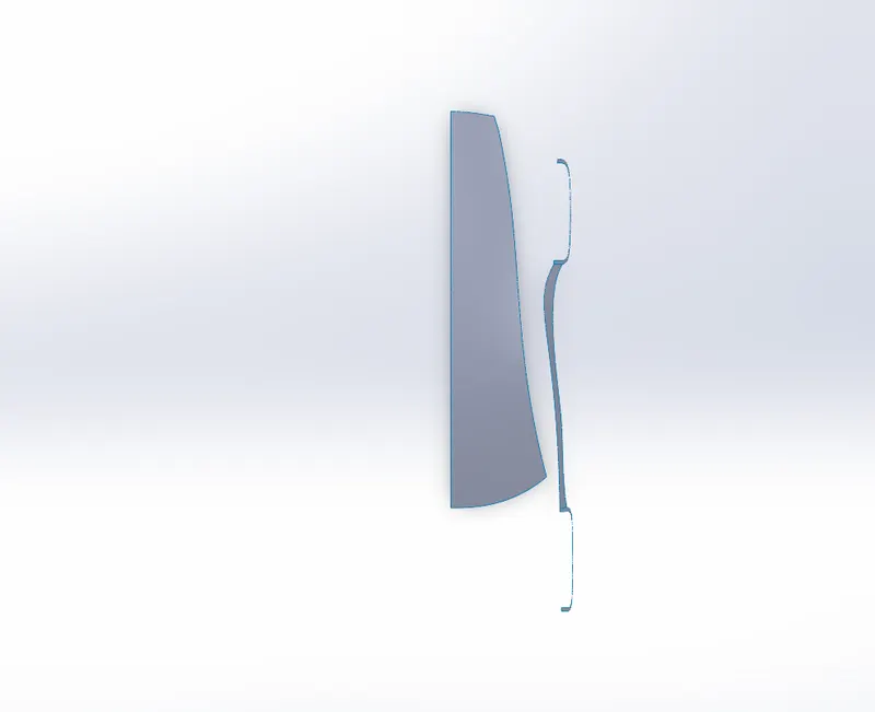
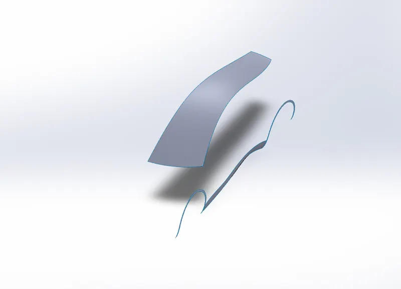
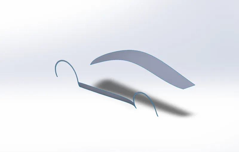
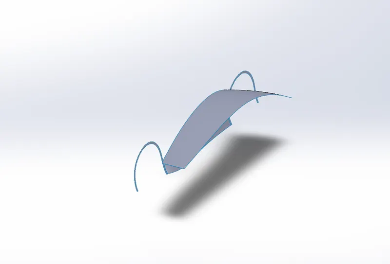
Lower portion of the door is to be created by many sketches on the side plane and top plane, go to curve and choose projective curve and select two sketches and then validate this step will repeat many times and then use surface boundaty surface tool
Views:
Isometric:
Fenders:
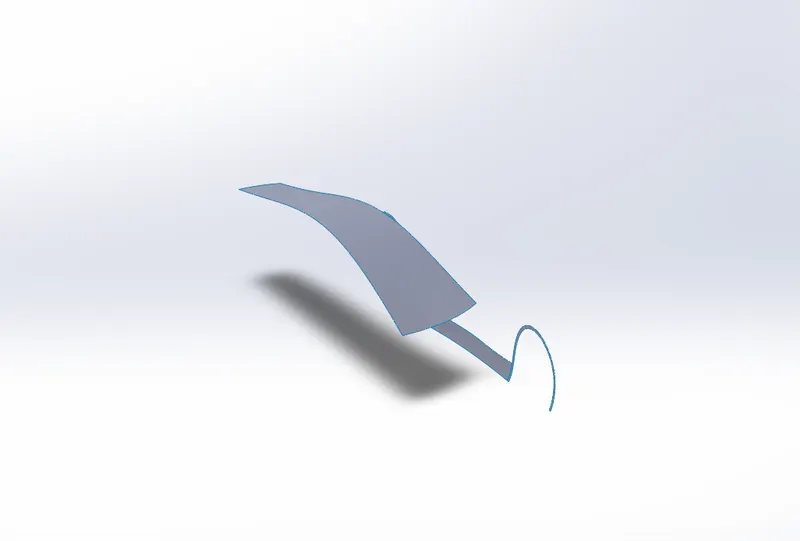
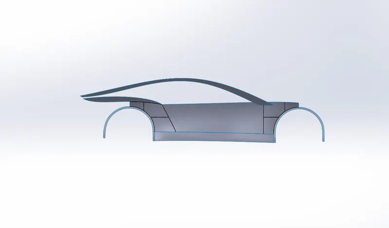
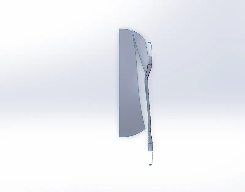
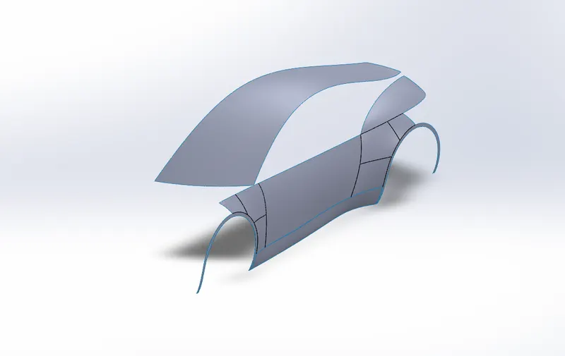
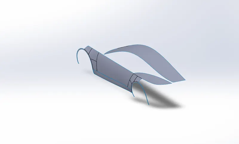
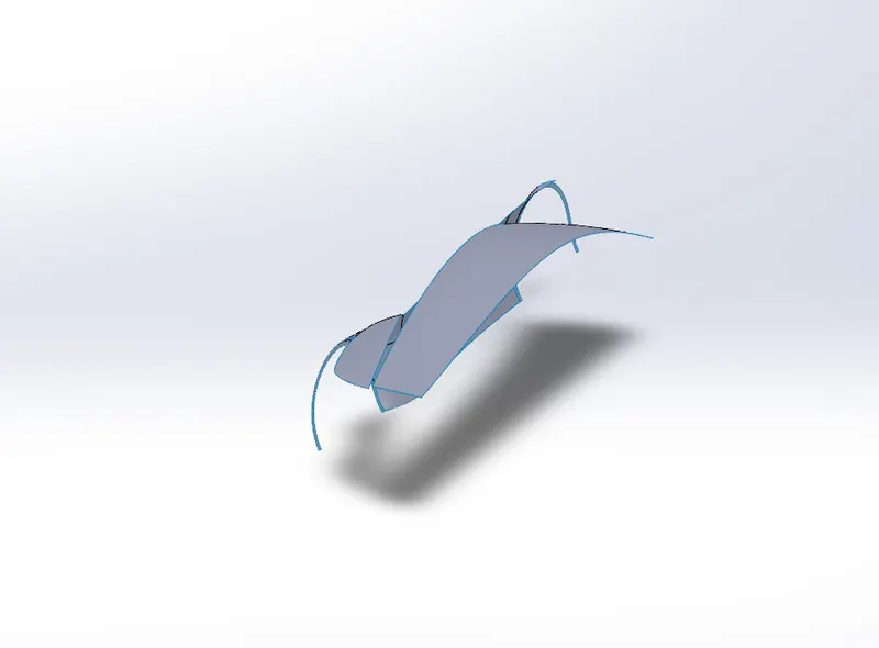
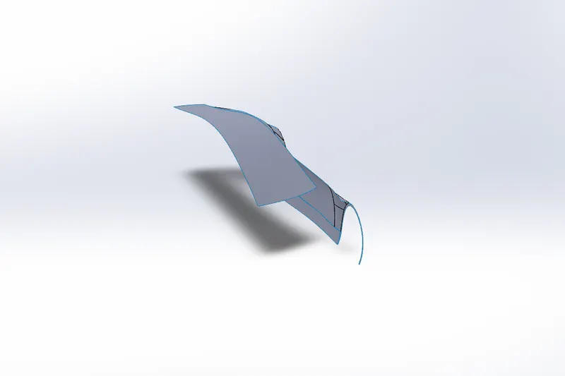
The surface above the wheel is called a fender. fender gives a graphics design of the car so it is very important to sketch the fender with proper dimension.To create a fender we can use the sketches on the side and top plane, make a projective curve(go to the feature manager,After that use boundary surface then use trim tool to cut the extra part.
Views:
Isometic:
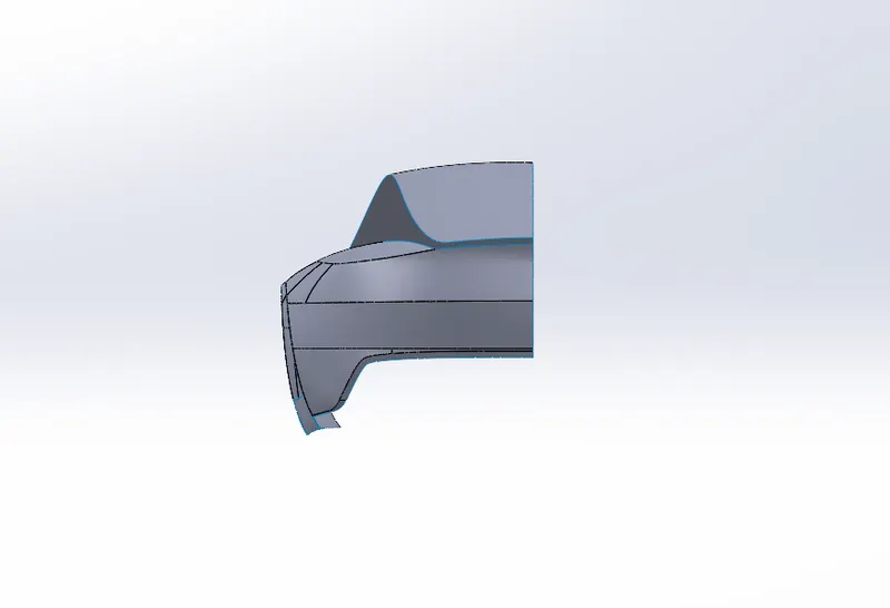
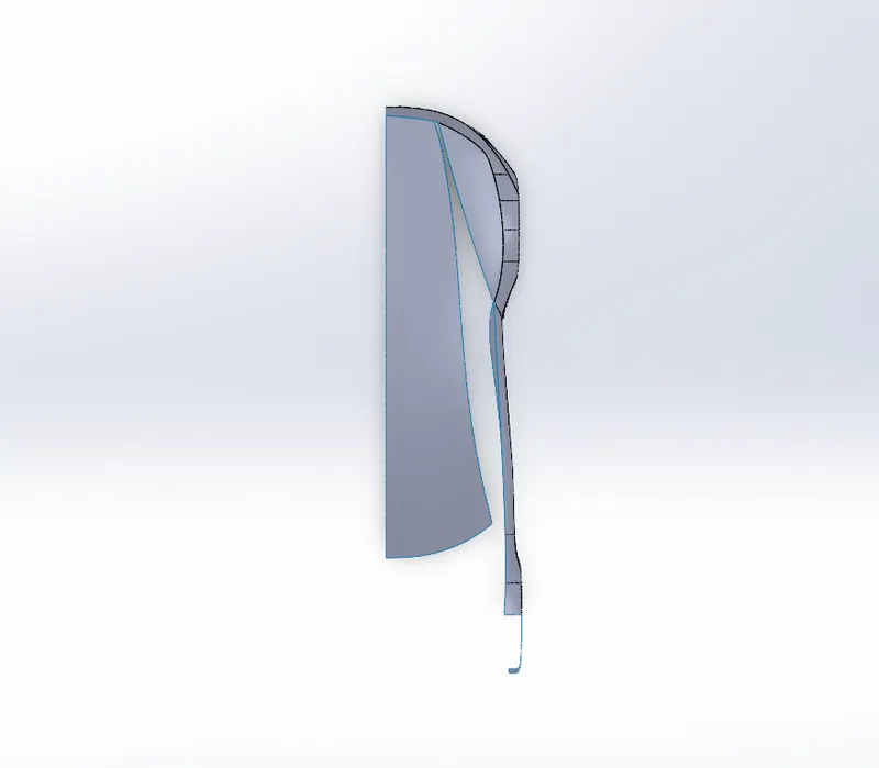
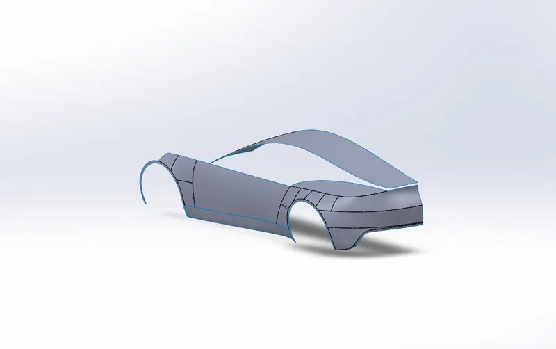
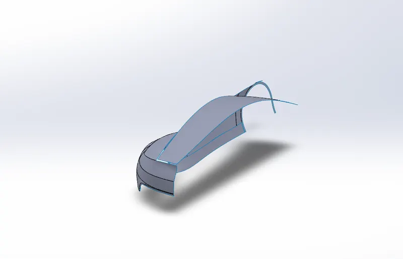
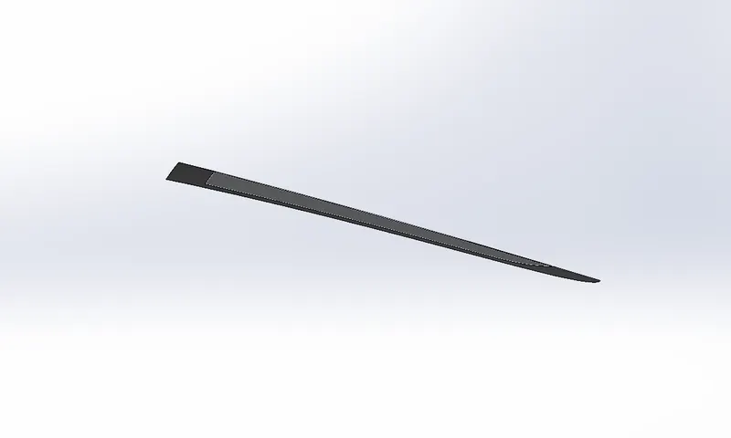
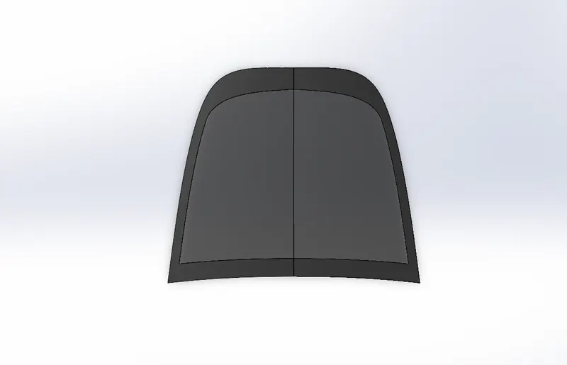
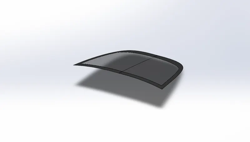
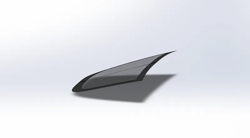
Rear:
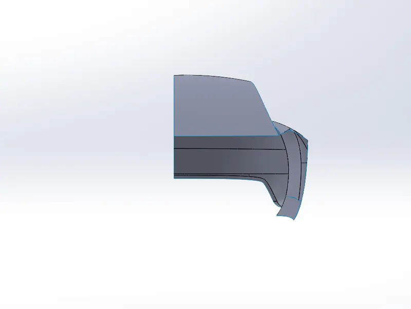
To create a rear area of vehicle we can use the sketches on the side and top plane, make a projective curve After that use boundary surface then use trim tool to cut the extra part.
Views:
Isometric:
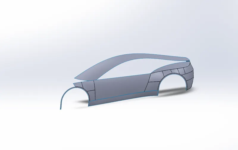
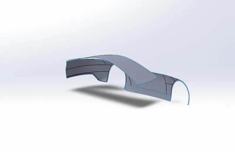
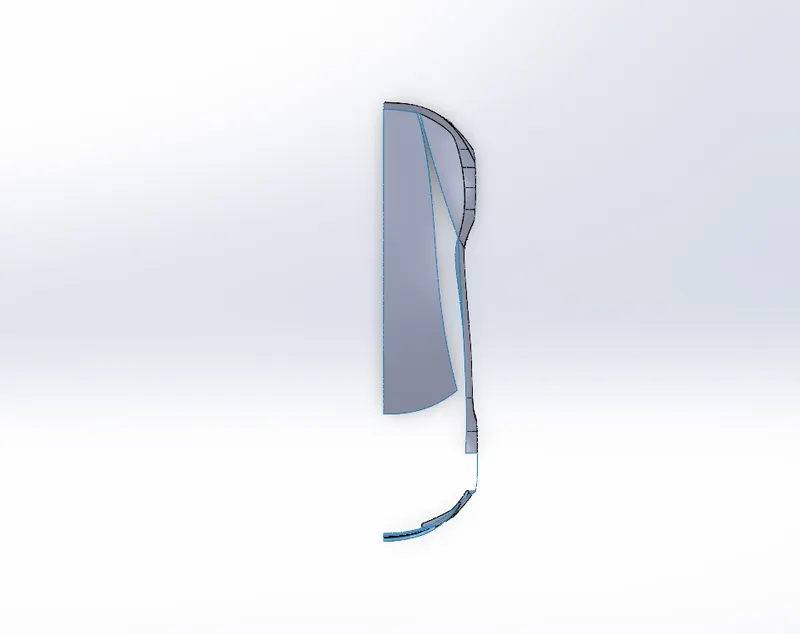
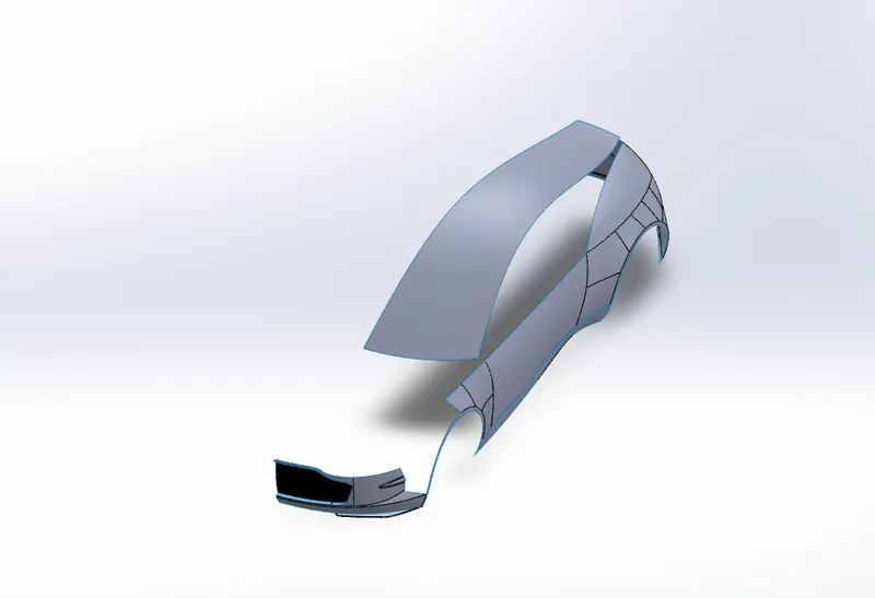
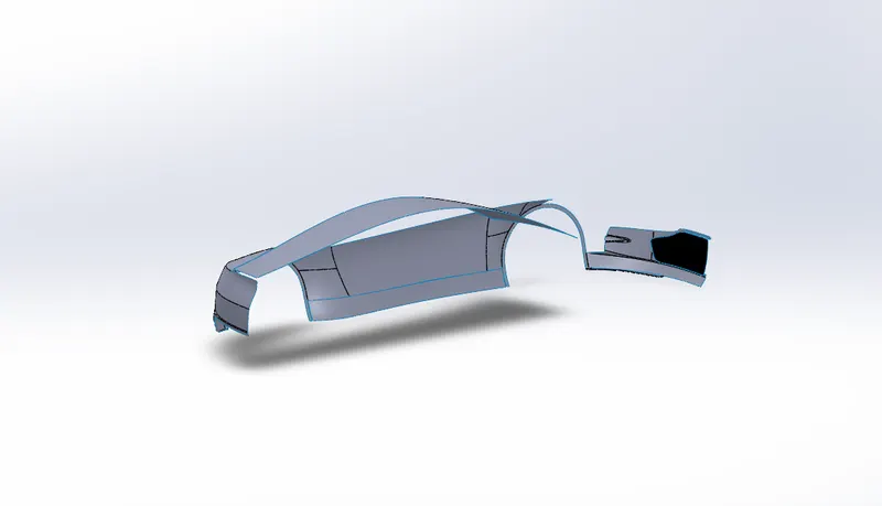
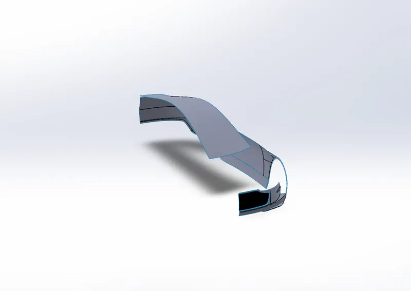
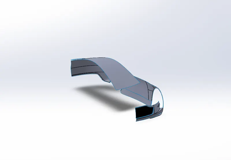
Front Bumper:
To create a front bumper of vehicle we can use the sketches on the side,top plane as well as front plane, make a projective curve After that use boundary surface then use trim tool to cut the extra part, and some adjustments.
View:
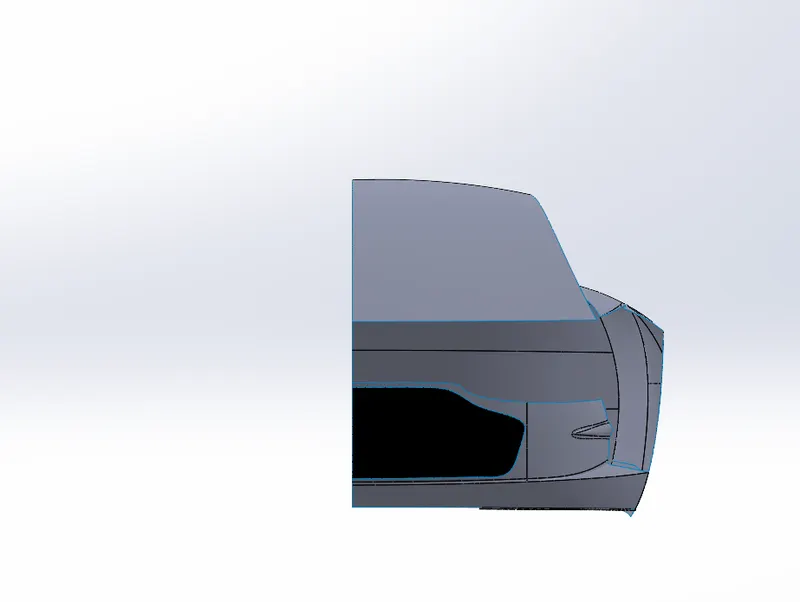
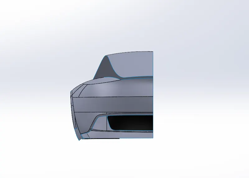
Isometric:
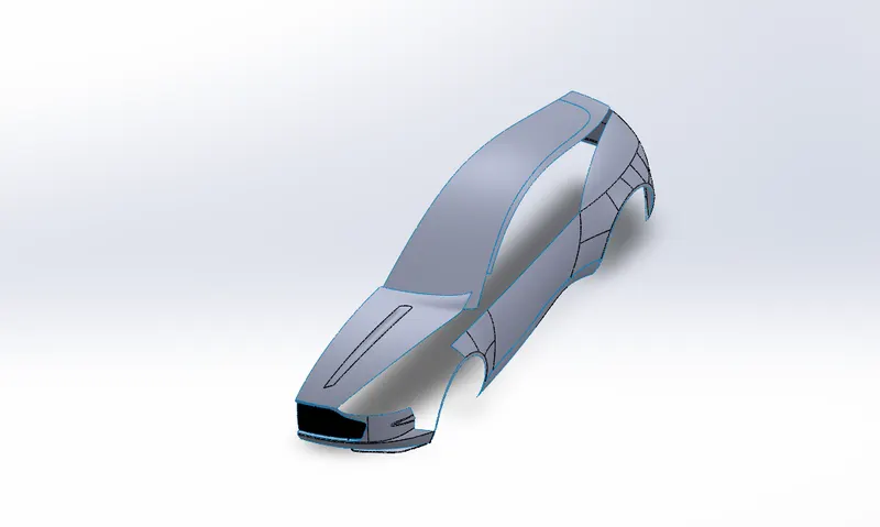
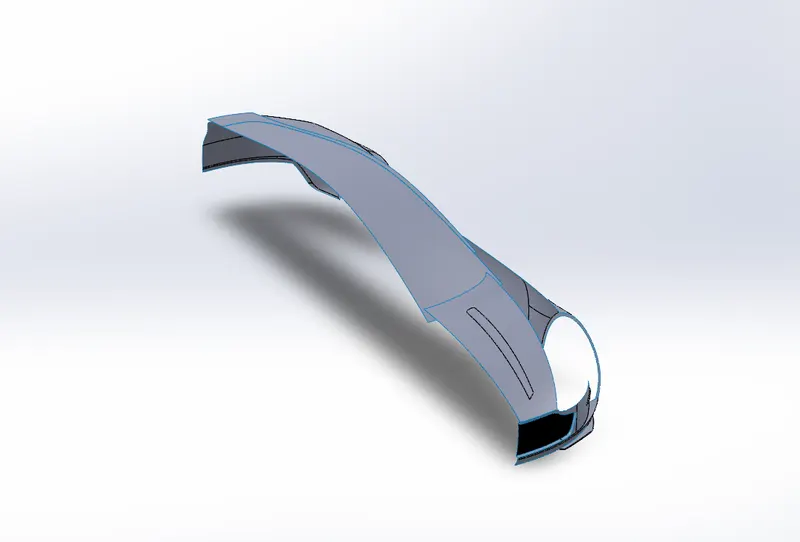
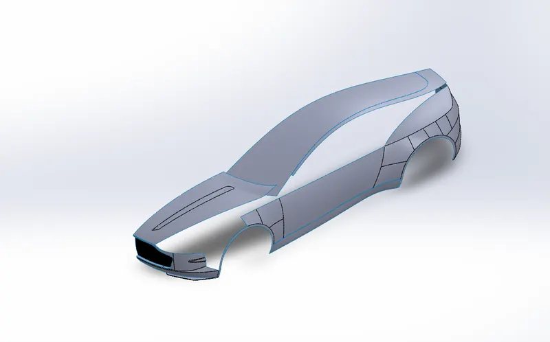
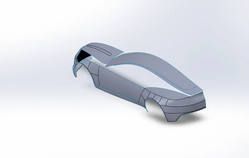
Hood:
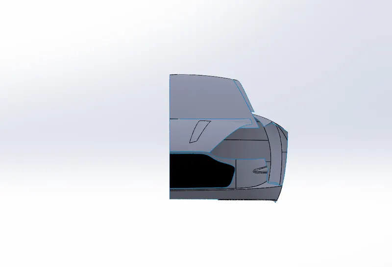
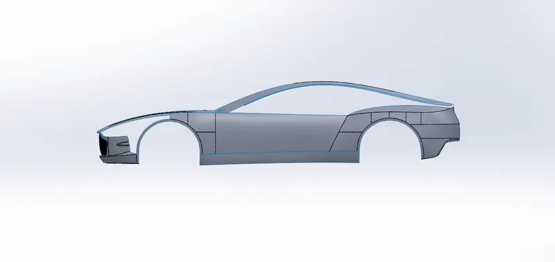
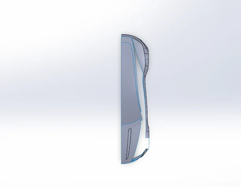
To create a hood of vehicle we can use the sketches on the side and top plane, make a projective curve After that use boundary surface tool then use trim tool to cut the extra part as well as ruled surface tool
Views:
Isometric:
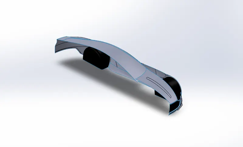
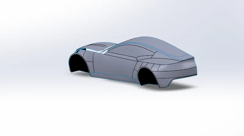
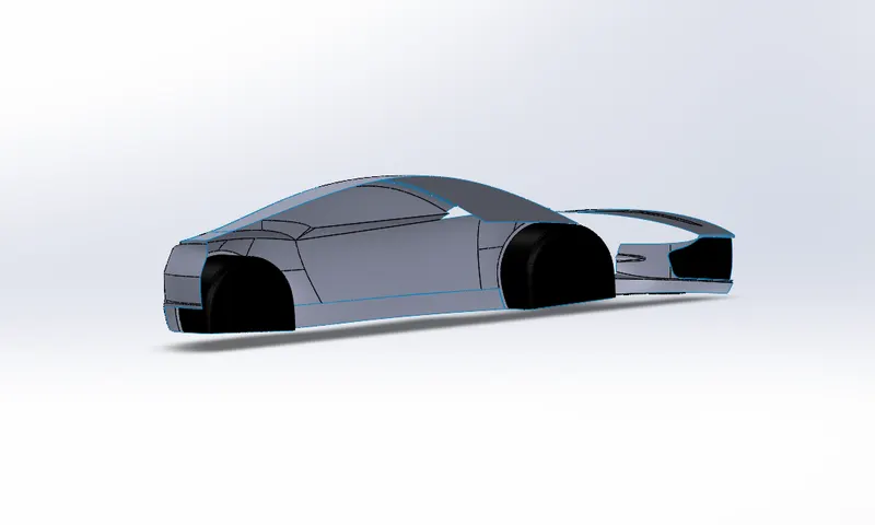
Window:
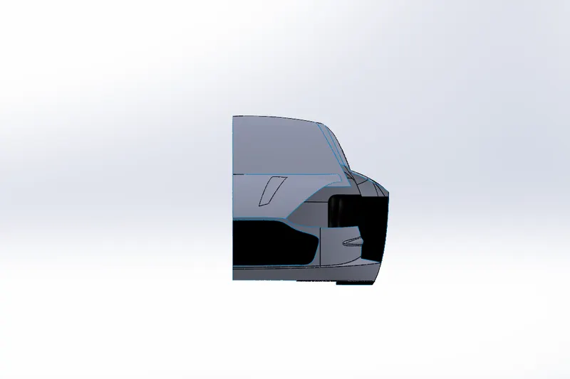
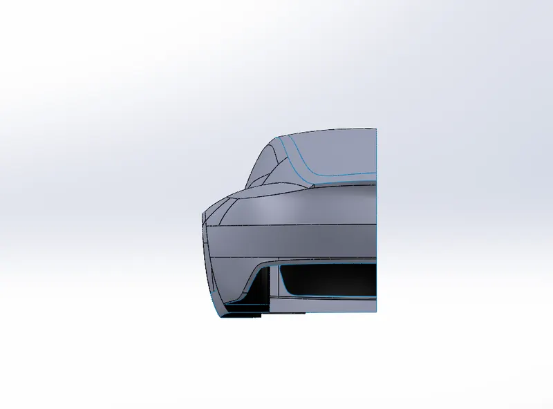
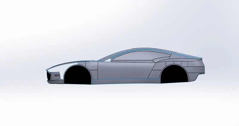
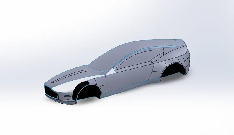
To create a window of vehicle we can use the sketches on the side front and top plane, then use boundary surface then use trim tool to cut the extra part and use split command
Views:
Isometric:
Door:
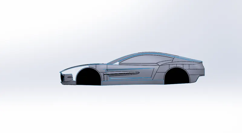
To create a door area of vehicle we can use the sketches on the side and top plane, make a projective curve After that use boundary surface then use trim tool to cut the extra part and rooled surface.
Views:
Isometric:
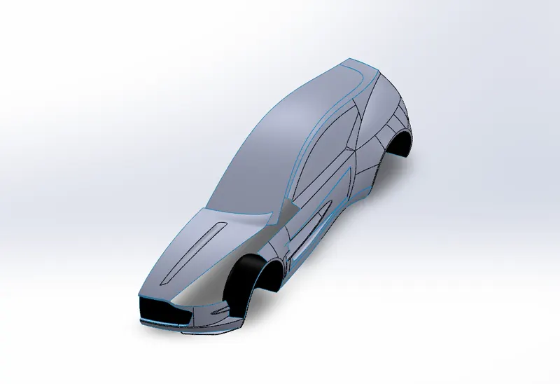
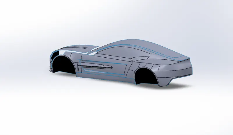
Front Wing:
TOOLS USED
Sketch Tools:
- Spline
- Line
- Circle
- Offset Entities
- Convert Entities
Surface Tools:
- Surface knit
- Surface Extend
- Offset Surface
- Move/ copy bod
Feature Tools:
- Trim
- Fillet
- Extrude Cut
- Combine
- Extrude Boss/ Base
Views:
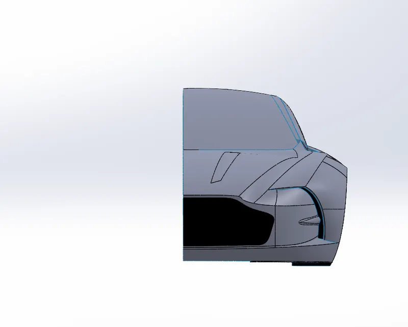
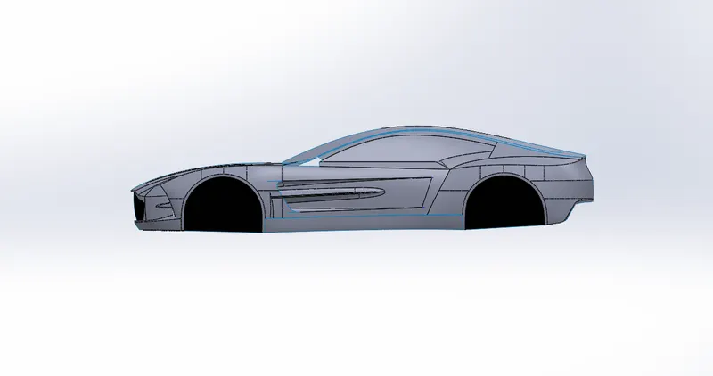
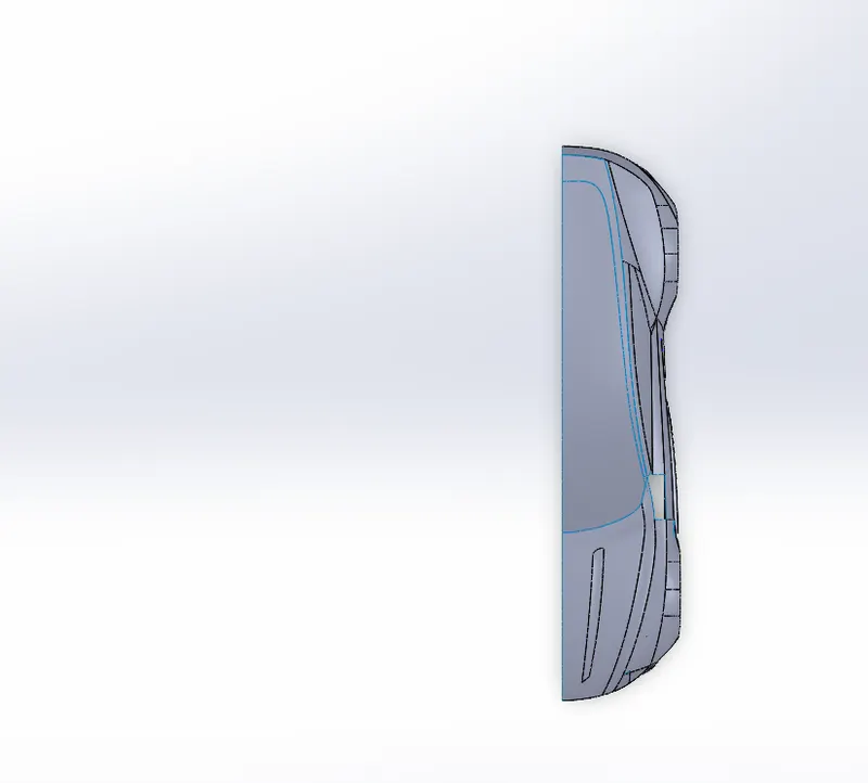
Isometric:
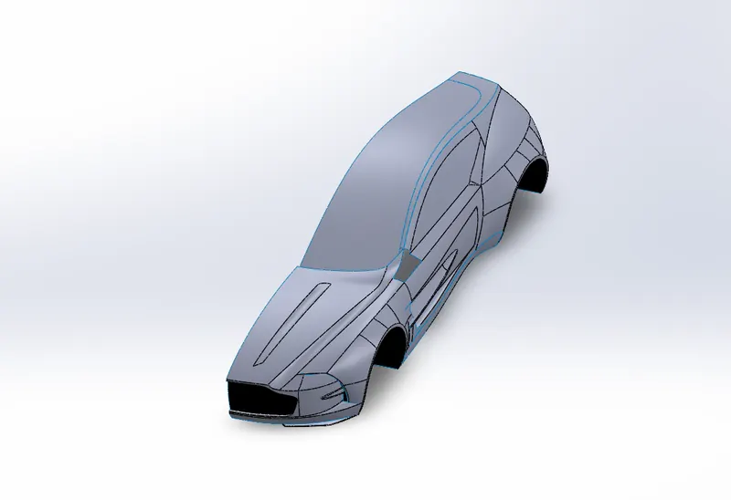
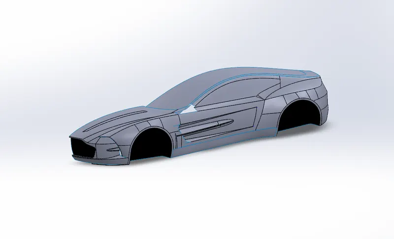
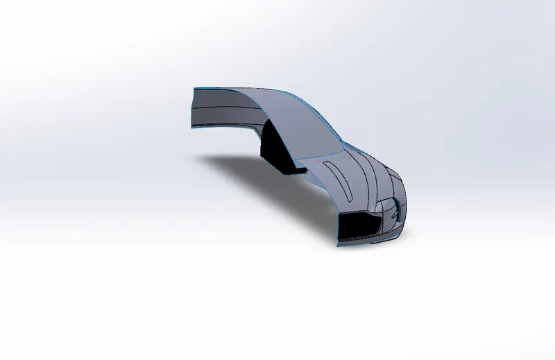
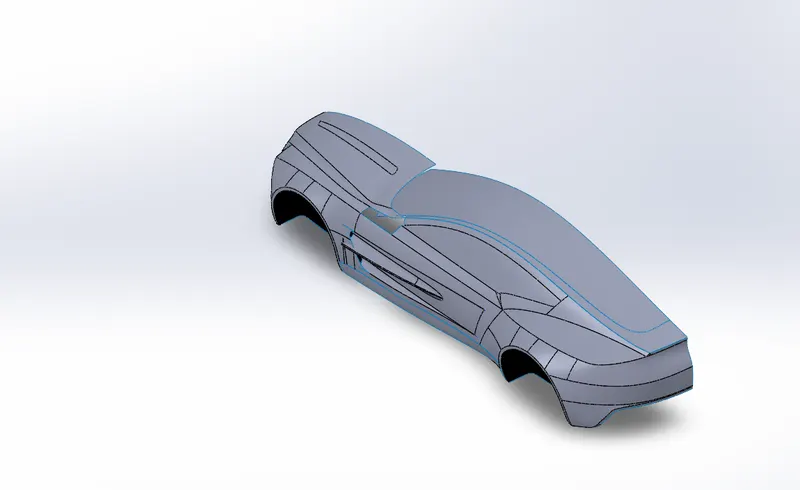
ROOF 2
TOOLS USED
Sketch Tools:
- Spline
- Line
- Circle
- Offset Entities
- Convert Entities
Surface Tools:
- Surface knit
- Surface Extend
- Offset Surface
- Move/ copy bod
Feature Tools:
- Trim
- Fillet
- Extrude Cut
- Combine
- Extrude Boss/ Base
Views:
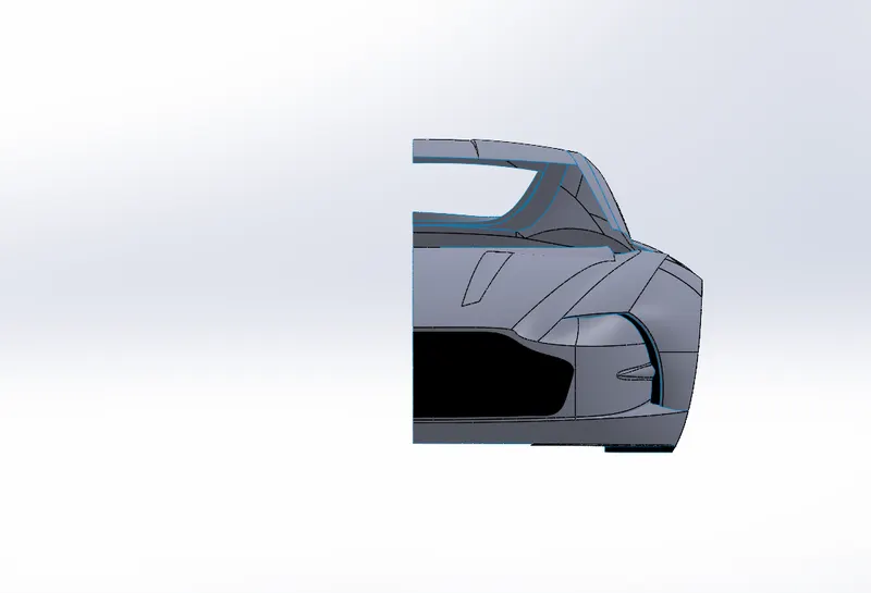
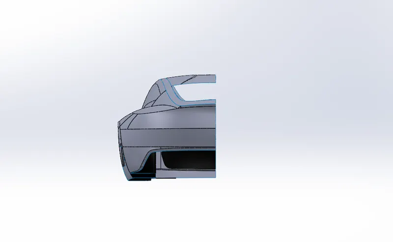
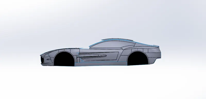
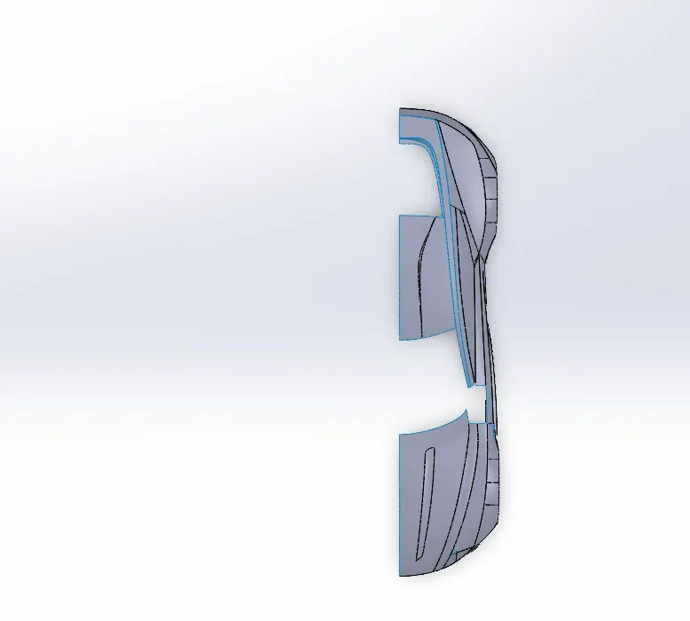
Isometric:
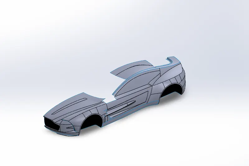
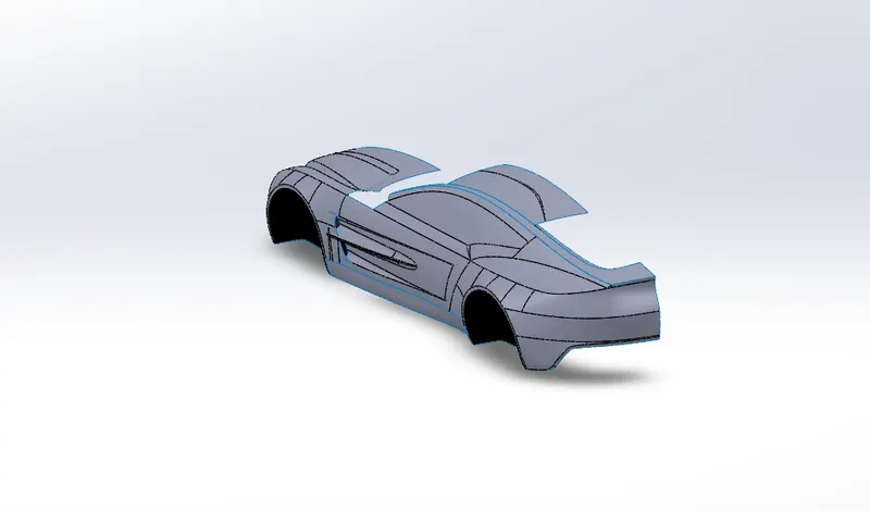
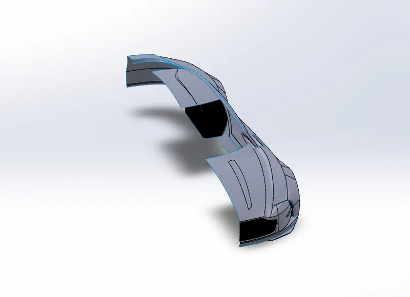
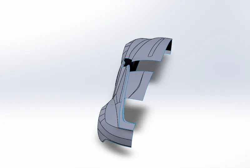
SIDE2:
TOOLS USED
Sketch Tools:
- Spline
- Line
- Circle
- Offset Entities
- Convert Entities
Surface Tools:
- Surface knit
- Surface Extend
- Offset Surface
- Move/ copy bod
Feature Tools:
- Trim
- Fillet
- Extrude Cut
- Combine
- Extrude Boss/ Base
Views:
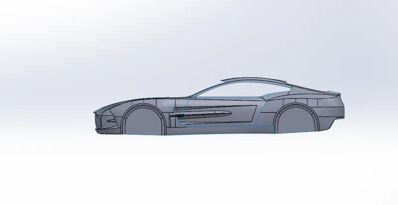
Isometric:
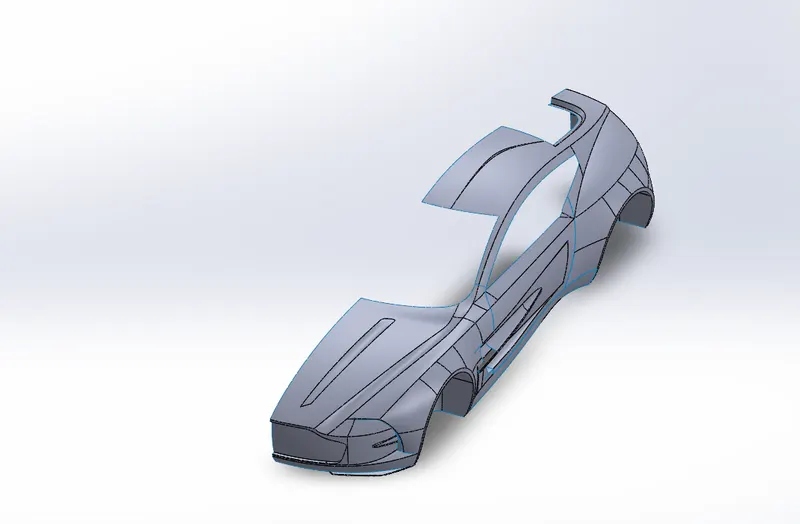
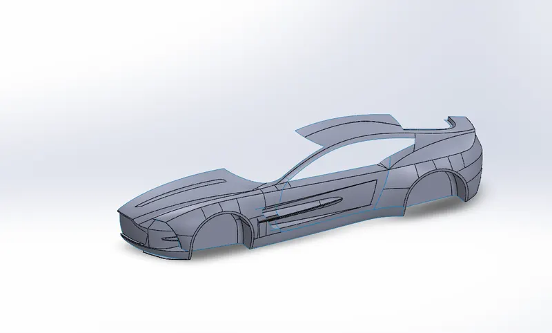
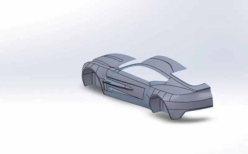
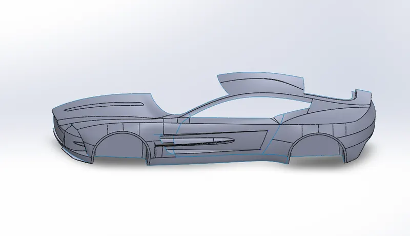
HOOD2:
TOOLS USED
Sketch Tools:
- Spline
- Line
- Circle
- Offset Entities
- Convert Entities
Surface Tools:
- Surface knit
- Surface Extend
- Offset Surface
- Move/ copy bod
Feature Tools:
- Trim
- Fillet
- Extrude Cut
- Combine
- Extrude Boss/ Base
Views:
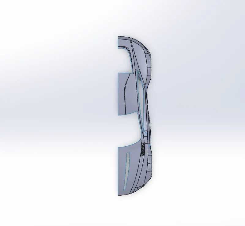
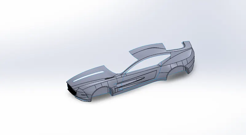
Isometric:
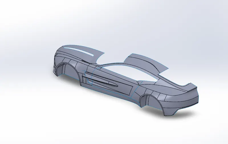
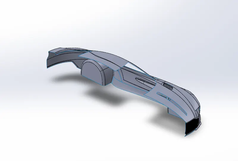
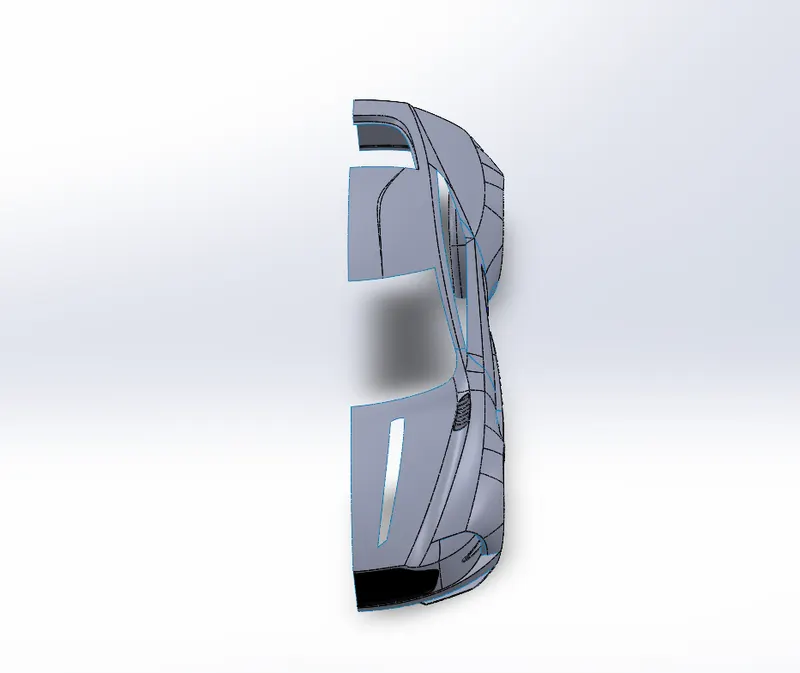
REAR BUMPER:
TOOLS USED
Sketch Tools:
- Spline
- Line
- Circle
- Offset Entities
- Convert Entities
Surface Tools:
- Surface knit
- Surface Extend
- Offset Surface
- Move/ copy bod
Feature Tools:
- Trim
- Fillet
- Extrude Cut
- Combine
- Extrude Boss/ Base
Views:
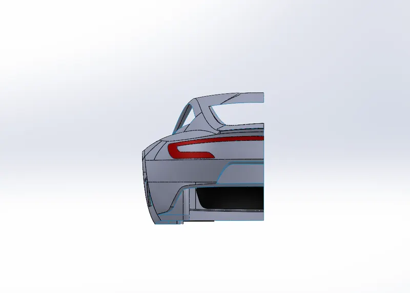
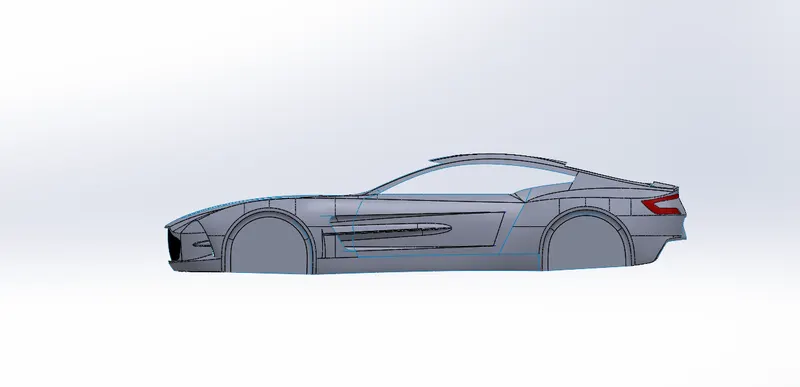
Isometric:
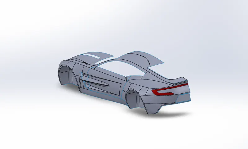
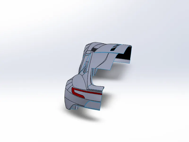
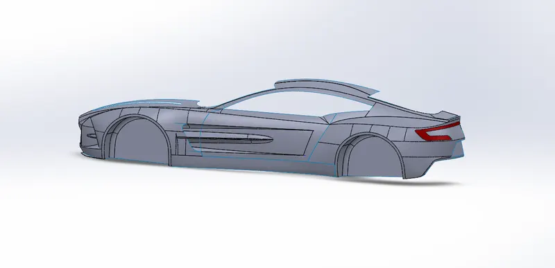
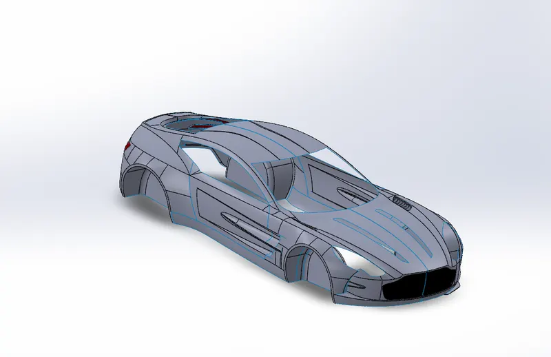
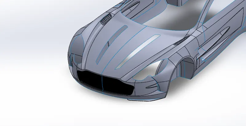
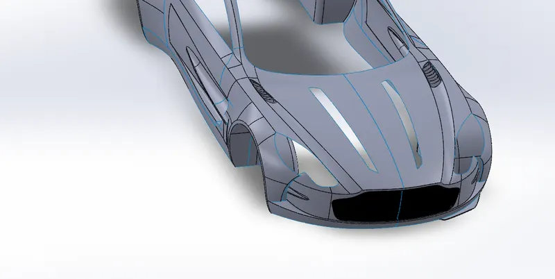
LIGHT:
View:
Isometric:
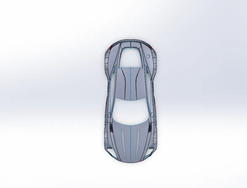
FUEL AREA:
TOOLS USED
Sketch Tools:
- Spline
- Line
- Circle
- Offset Entities
- Convert Entities
Surface Tools:
- Surface knit
- Surface Extend
- Offset Surface
- Move/ copy bod
Feature Tools:
- Fillet
- Extrude Cut
- Combine
- Extrude Boss/ Base
View:
Isometric:
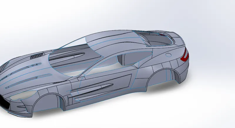
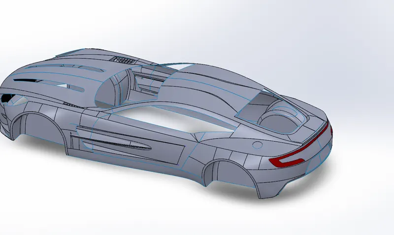
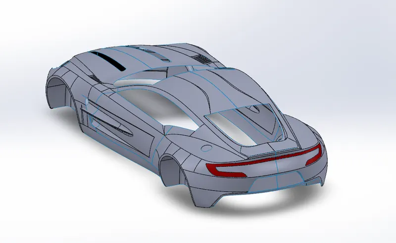
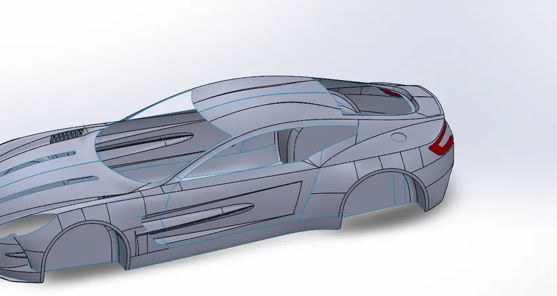
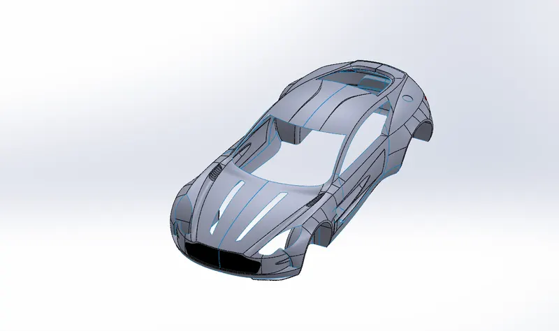
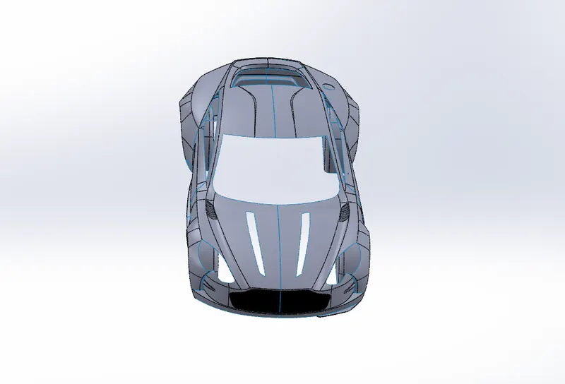
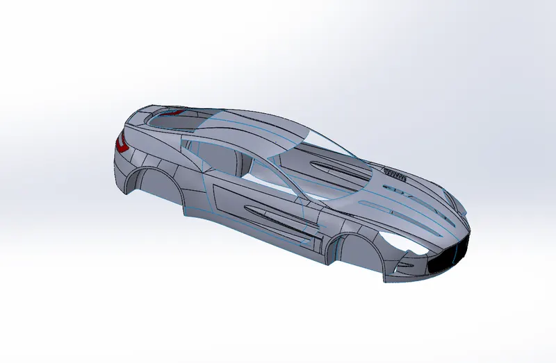
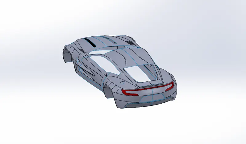
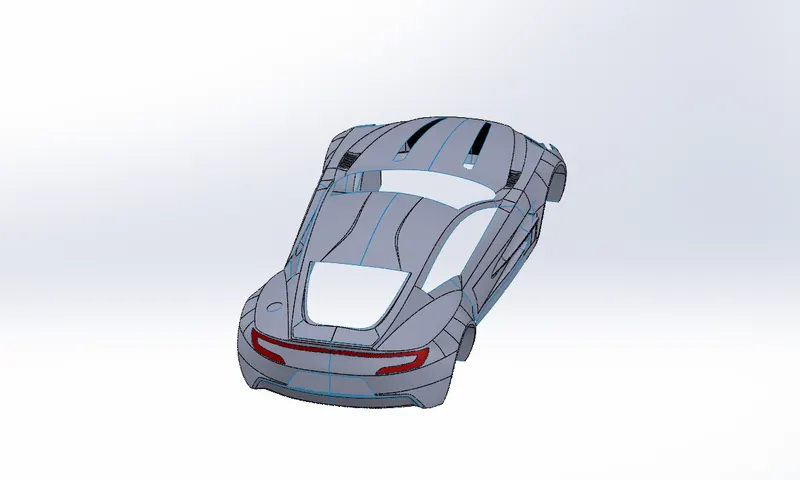
Main Body:
TOOLS USED
Sketch Tools:
- Spline
- Line
- Circle
- Offset Entities
- Convert Entities
Surface Tools:
- Surface knit
- Surface Extend
- Offset Surface
- Move/ copy bod
Feature Tools:
- Trim
- Fillet
- Extrude Cut
- Combine
- Extrude Boss/ Base
View:
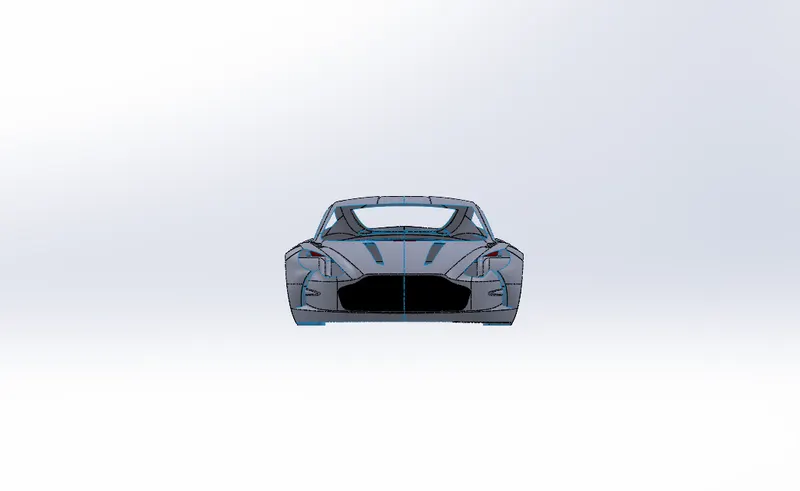
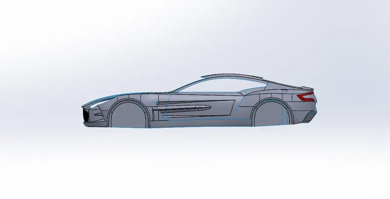
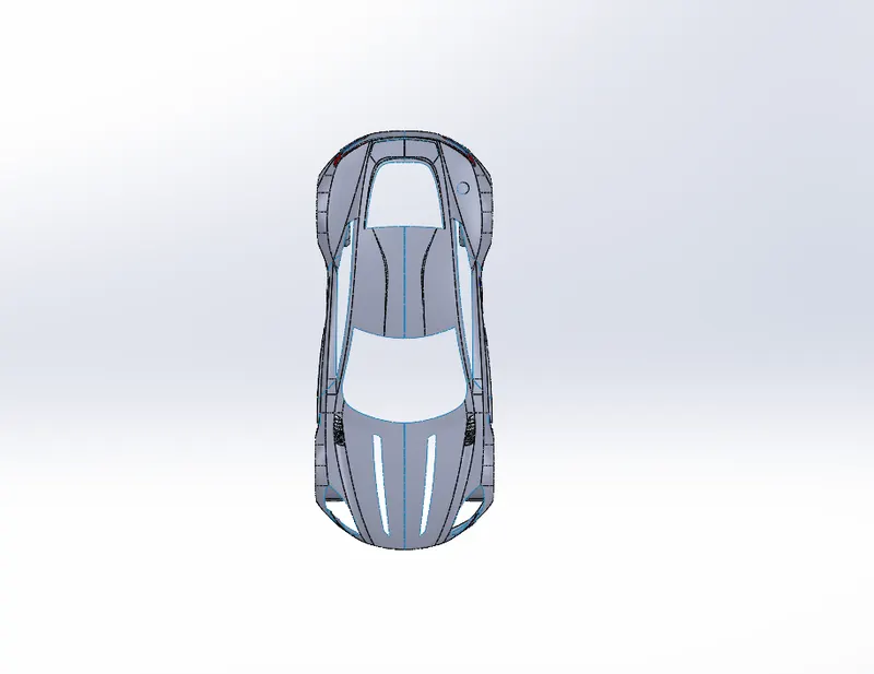
Isometric:
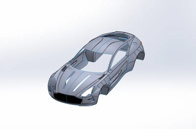
COMPONENT:
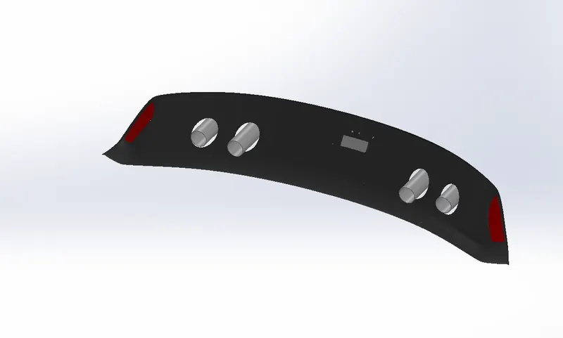
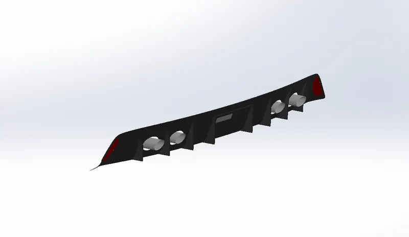
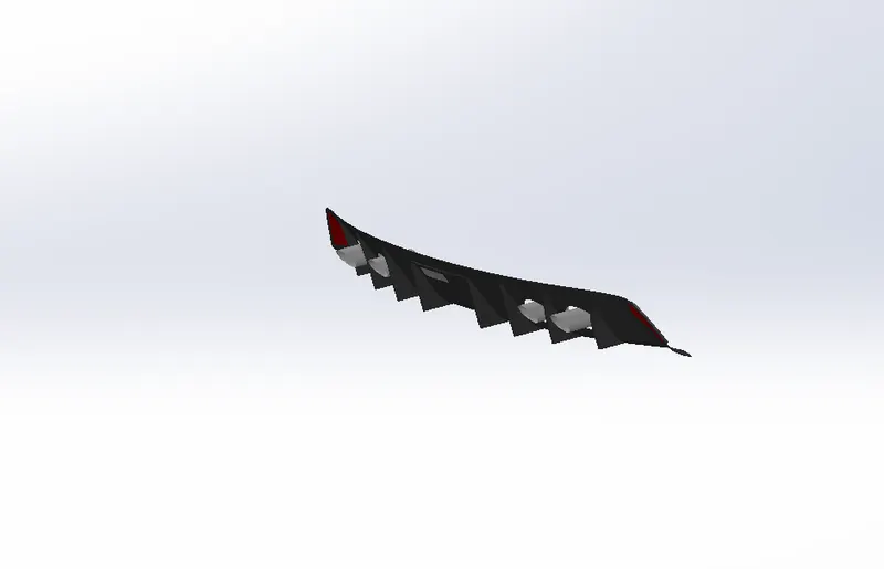
Rear Bumper:-
Rear bumper is part of the car body, it is the back surface above the rear wheel. The rear bumper gives look from the rear side of the car so it is a very important thing in the whole car body. While creating a rear bumper be careful of dimensioning the sketch.
first start sketch on the top plane .Take reference plane 48 cm above from top plane , rename this plane as planeh48 for future use start a sketch on this plane.Again start a sketch on the side plane and dimension it Once again take reference plane but this time chooses right plane and give a distance of 55 cm, rename the plane as planev55 for future use. start sketch on this plane,In this way, we sketched many sketches and then apply boundary surface ,While applying boundary surface, the surface with the right plane must be normal to profile.Delete the extra surface ,Knit the rear bumper with fender surface
TOOLS USED
Sketch Tools:
- Spline
- Line
- Circle
- Offset Entities
- Convert Entities
- 3D sketch
Surface Tools:
- Surface Trim
- Surface Extrude
- Boundary Surface
- Surface Fill
- Surface knit
- Ruled Surface
- Offset Surface
- Surface Extend
Feature Tools:
- Projected Curve
- Reference Plane
- Trim
- Extrude Boss
- Extrude Cut
- Move/Copy
- Mirror
- Appearance
Views:
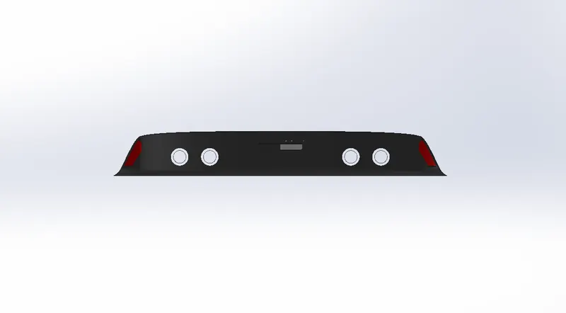
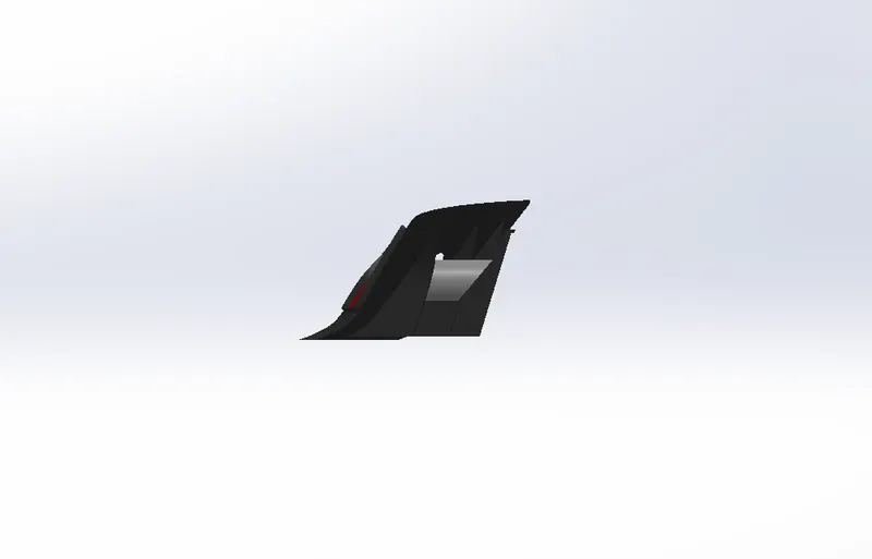
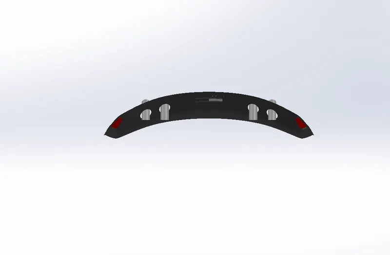
Isometric:

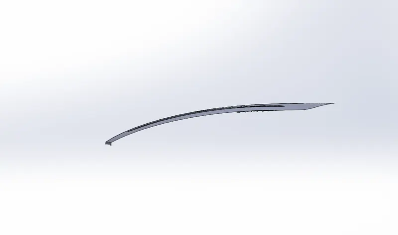
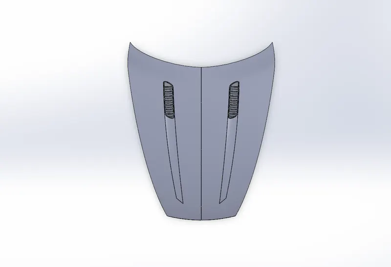
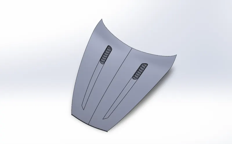
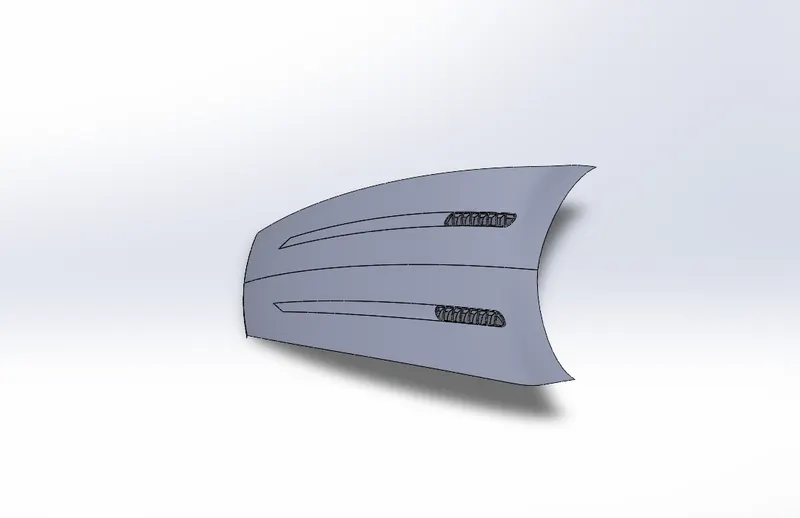
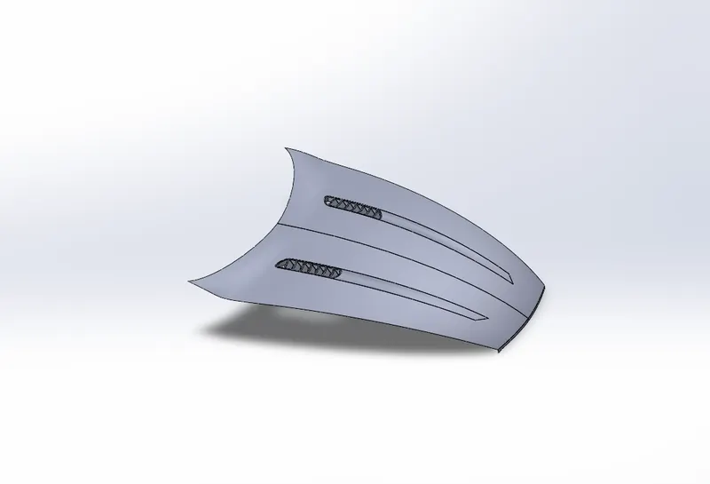
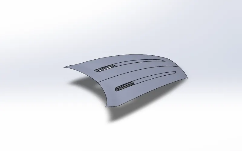
Hood:
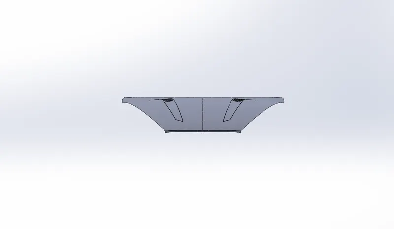
The hood or bonnet is the hinged cover over the engine of motor vehicles. Hood can open to allow access to the engine compartment or trunk on the rear engine for maintenance and repair.
For designing the hood we have taken special care because it is the front part of car and it gives very high defination look,so its surface must be perfect.First, start with a sketch on the top plane.start a sketch on the side plane, the purpose of the sketches to draw the projective curve.The projective curve gives 3d shape of the body,take reference plane w.r.t front plane at 70 cm distance,take another reference plane from a front plane at a distance of 115cm,Apply boundary surface and surface .
The hood or bonnet is the hinged cover over the engine of motor vehicle.Hoods can open to allow access to the engine compartment, or trunk for maintenance and repair.
TOOLS USED
Sketch Tools:
- Spline
- Line
- Circle
- Offset Entities
- Convert Entities
- 3D sketch
Surface Tools:
- Surface Trim
- Surface Extrude
- Boundary Surface
- Surface Fill
- Surface knit
- Ruled Surface
- Offset Surface
- Surface Extend
- Move/ copy body
- Cut with Surface
Feature Tools:
- Projected Curve
- Reference Plane
- Trim
- Split
- Fillet
- Linear Pattern
- Extrude Cut
- Combine
- Mirror
Views:
Isometric:
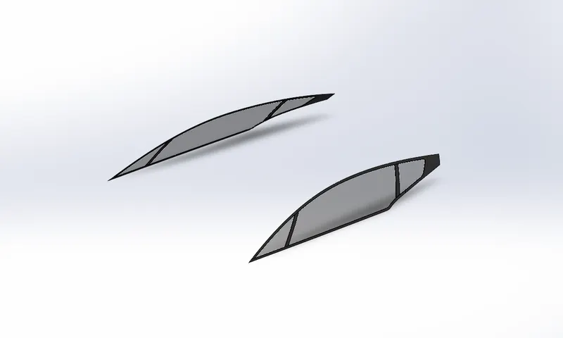
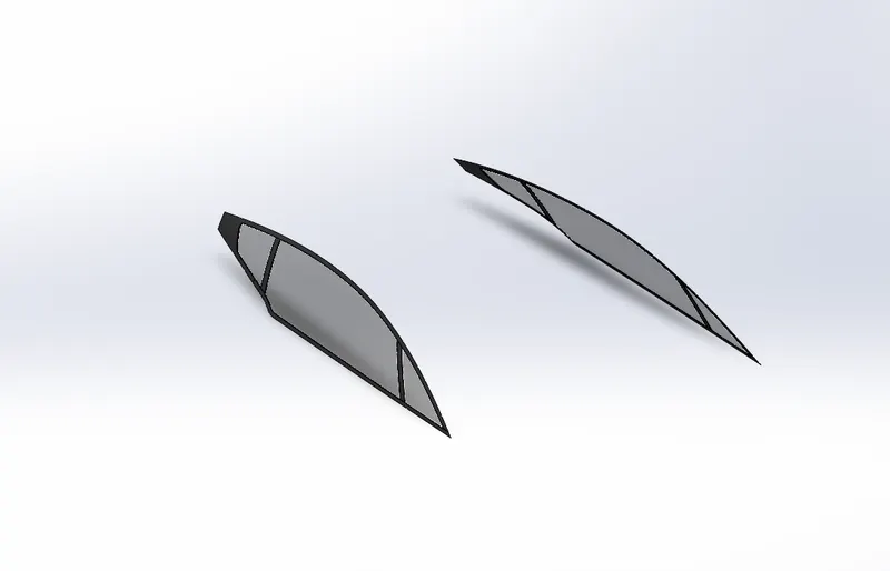
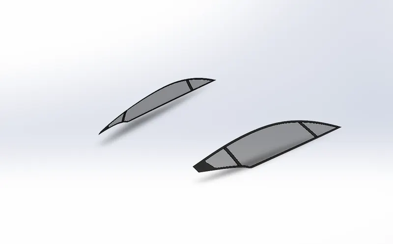
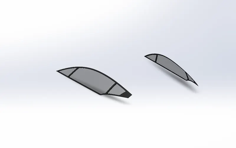
Window:
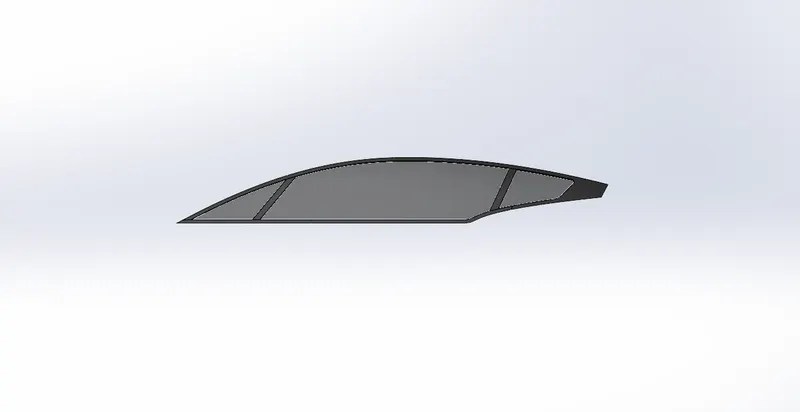
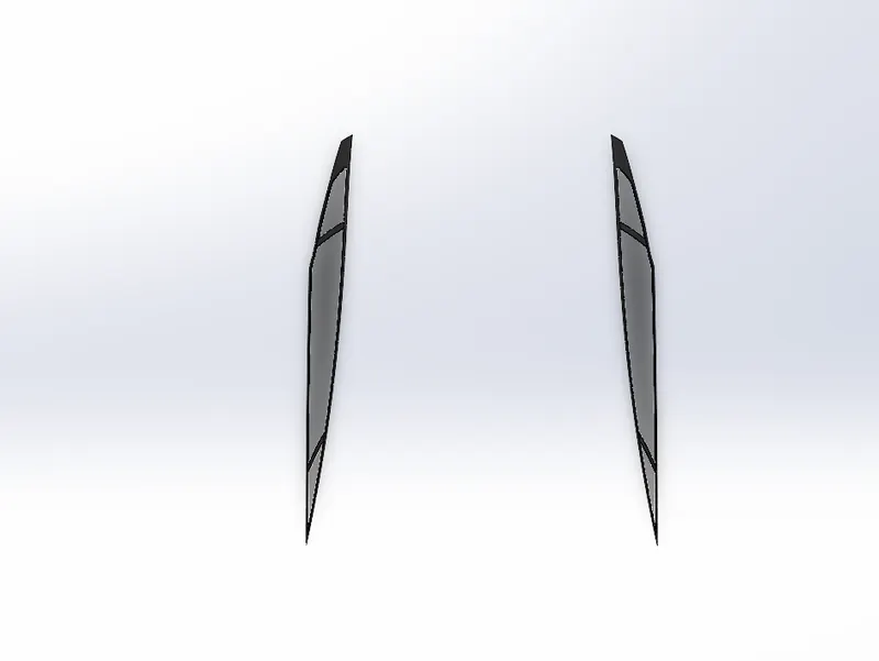
Window of the car is given to see outside of the car, it has transparent glass. The window is a very important part of a car because it gives good look moreover it can use as an emergency exit in case the door is self-locked.so to make the window of car,It is a surface modeling process so basic steps are to create the projective curve.Add reference plane for guide curve and draw sketches on it.After completing the basic sketches, just apply the boundary surface .it is quite an easy process as long as your sketches is right .
TOOLS USED
Sketch Tools:
- Spline
- Line
- Circle
- Offset Entities
- Convert Entities
- 3D sketch
Surface Tools:
- Surface Trim
- Surface Extrude
- Boundary Surface
- Surface Fill
- Surface knit
- Ruled Surface
- Offset Surface
- Surface Extend
- Move/ copy body
- Cut with Surface
Feature Tools:
- Projected Curve
- Reference Plane
- Trim
- Split
- Fillet
- Linear Pattern
- Extrude Cut
- Combine
- Mirror
Views:
Isometric:
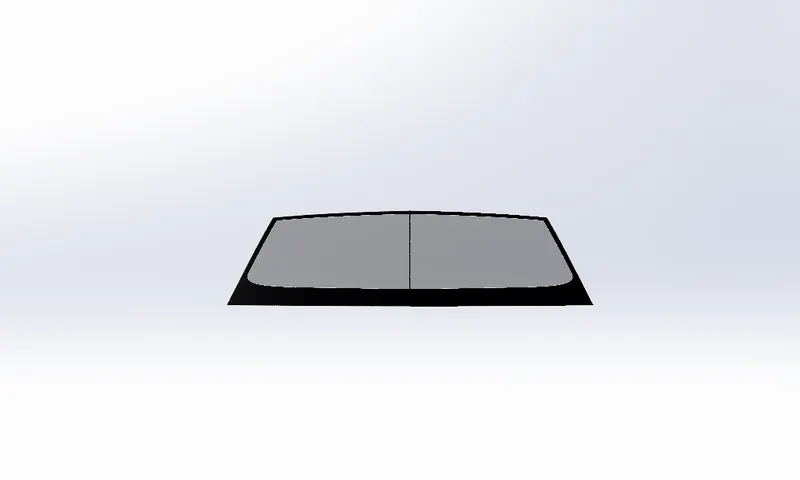
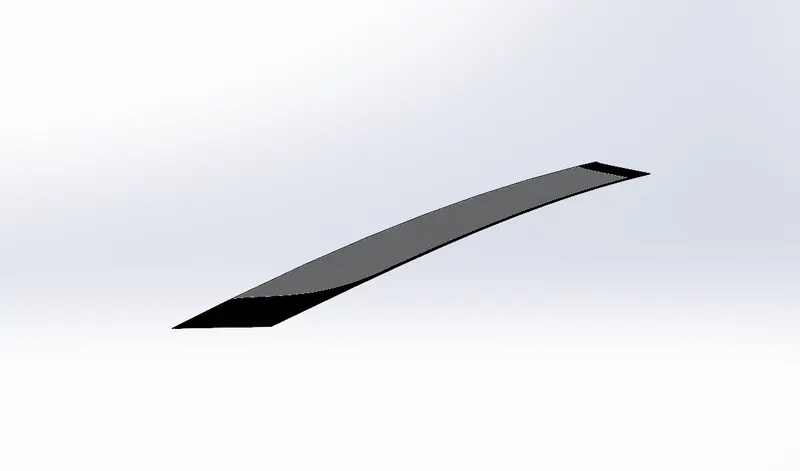
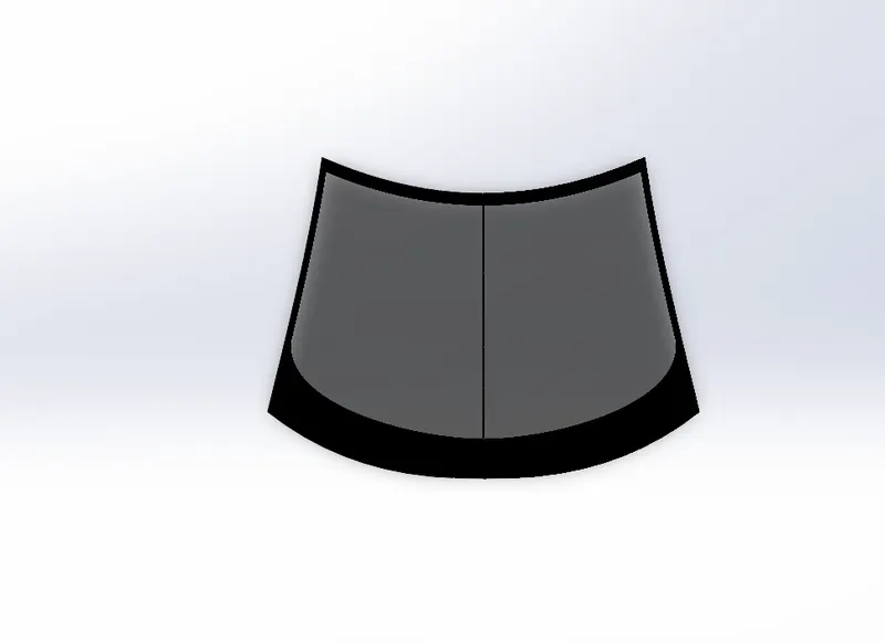
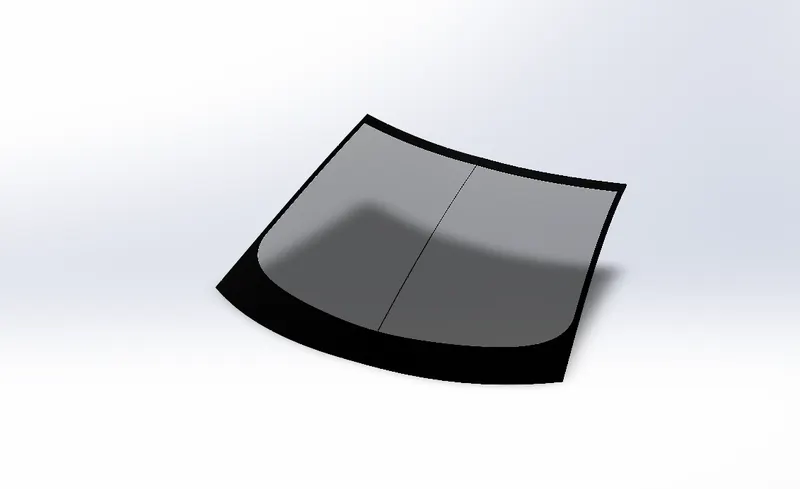
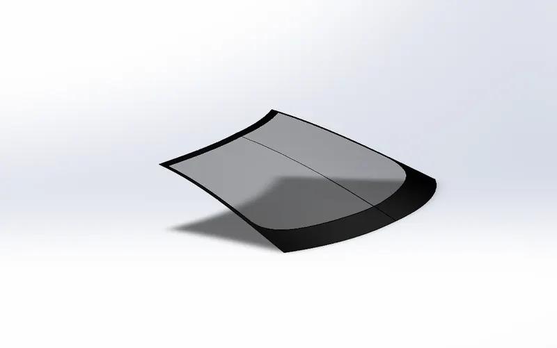
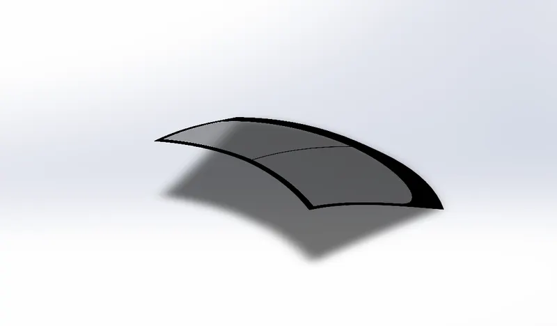
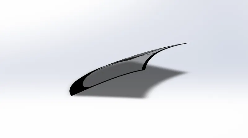
WINDSHIELD:
The windshield or windscreen is the front window, which provides visibility while protecting occupants from the elements. Modern windshields are generally made of laminated safety glass, a type of treated glass, which consists of, typically, two curved sheets of glass with a plastic layer laminated between them for safety, and bonded into the window frame.Windshields protect the vehicle's occupants from wind and flying debris such as dust, insects, and rocks, and provide an aerodynamically formed window towards the front.UV coating may be applied to screen out harmful ultraviolet radiation.
TOOLS USED
Sketch Tools:
- Spline
- Line
- Circle
- Offset Entities
- Convert Entities
- 3D sketch
Surface Tools:
- Surface Trim
- Surface Extrude
- Boundary Surface
- Surface Fill
- Surface knit
- Ruled Surface
- Offset Surface
- Surface Extend
- Move/ copy body
- Cut with Surface
Feature Tools:
- Projected Curve
- Reference Plane
- Trim
- Split
- Fillet
- Linear Pattern
- Extrude Cut
- Combine
- Mirror
Views:
Isometric:
REAR:
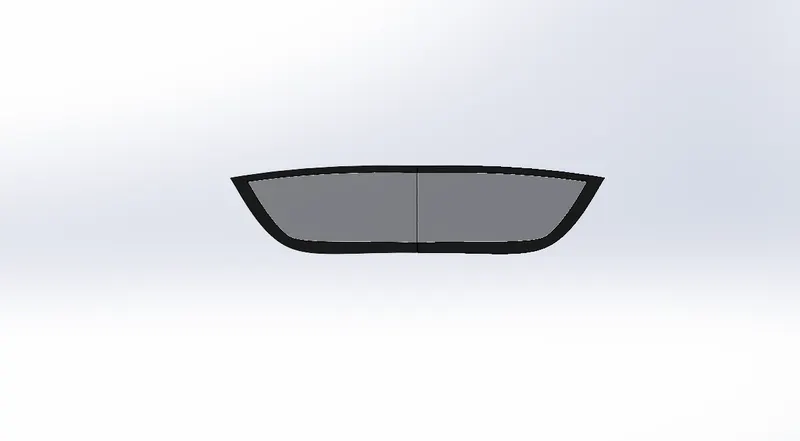
TOOLS USED
Sketch Tools:
- Spline
- Line
- Circle
- Offset Entities
- Convert Entities
- 3D sketch
Surface Tools:
- Surface Trim
- Surface Extrude
- Boundary Surface
- Surface Fill
- Surface knit
- Ruled Surface
- Offset Surface
- Surface Extend
- Move/ copy body
- Cut with Surface
Feature Tools:
- Projected Curve
- Reference Plane
- Trim
- Split
- Fillet
- Linear Pattern
- Extrude Cut
- Combine
- Mirror
Views:
Isometric:
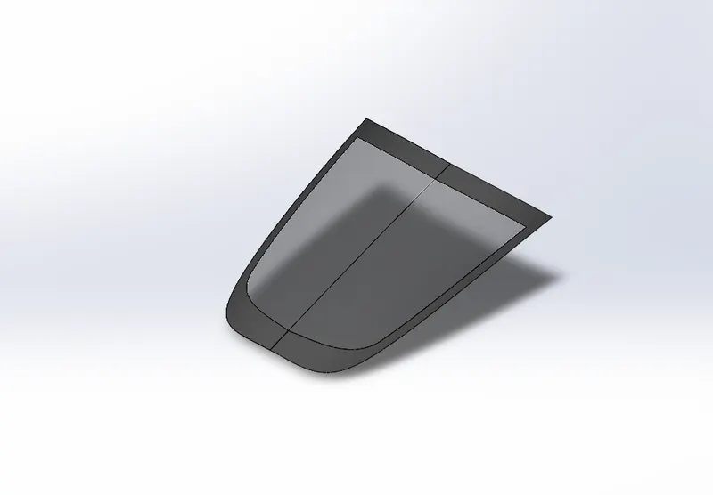
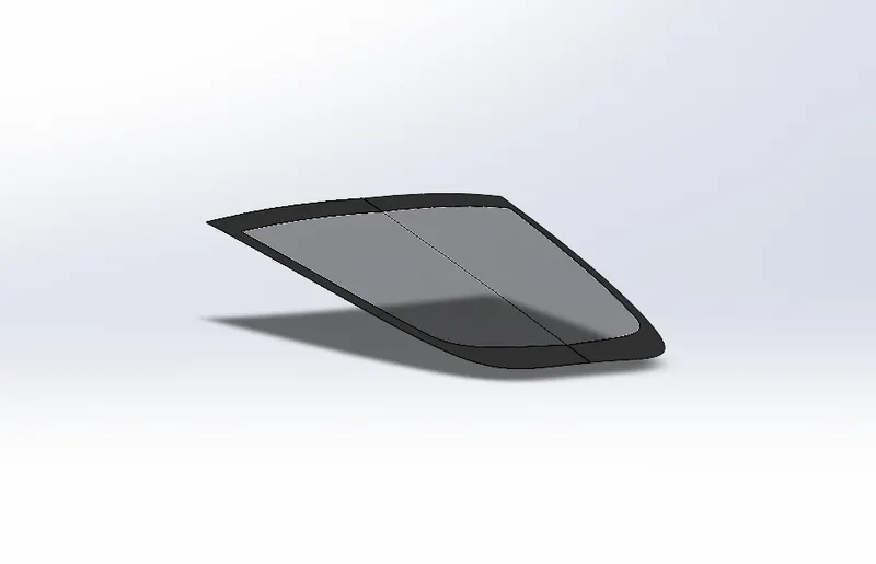
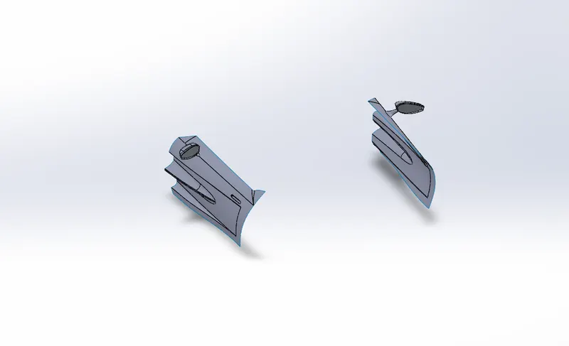
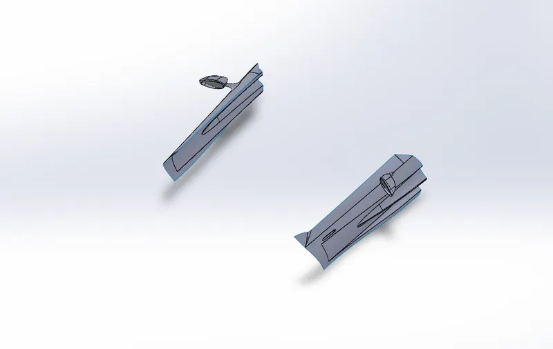
Doors:
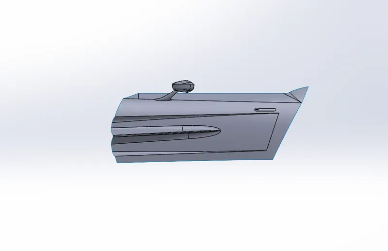
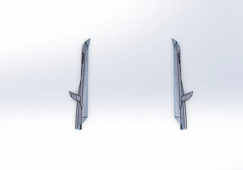
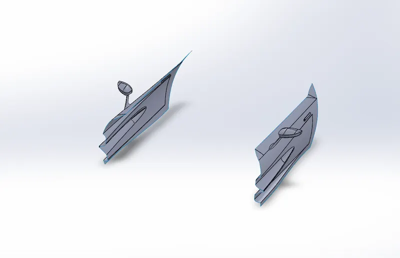
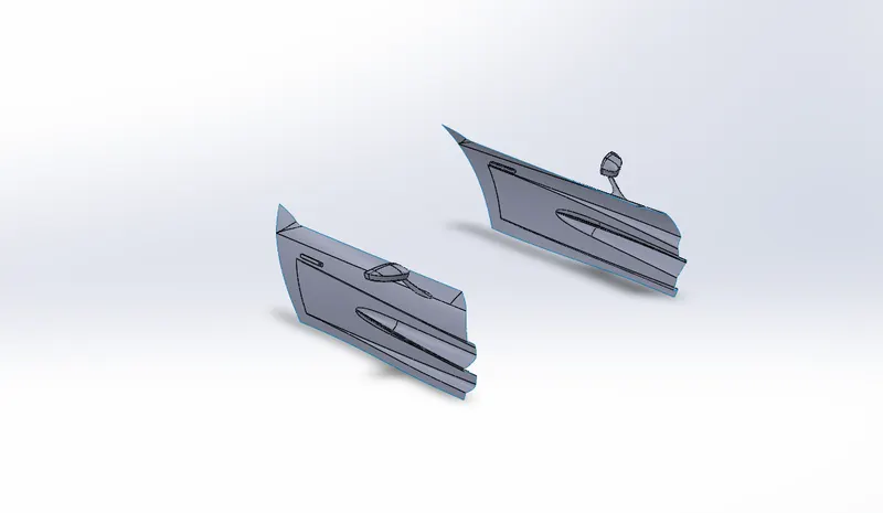
A car door is a type of door opening, typically hinged on its front edge, but sometimes attached by other mechanisms such as tracks, for entering and exiting a vehicle. Doors most often integrate side windows for visibility from inside the car and can be locked to secure the vehicle.Car doors may be manually operated or with power assist supplied by the vehicle.
Views:
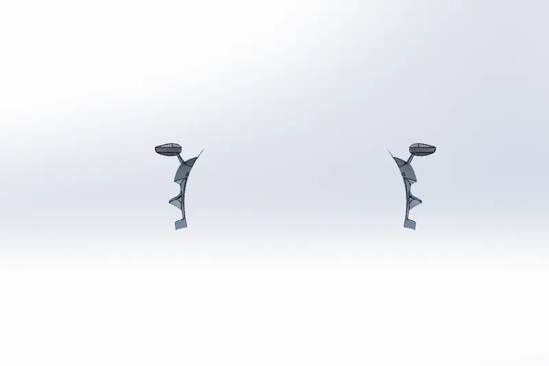
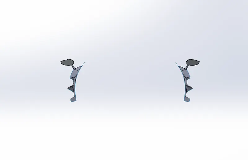
Isometric:
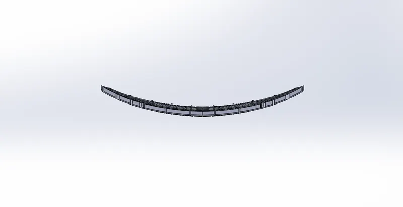
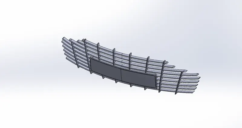
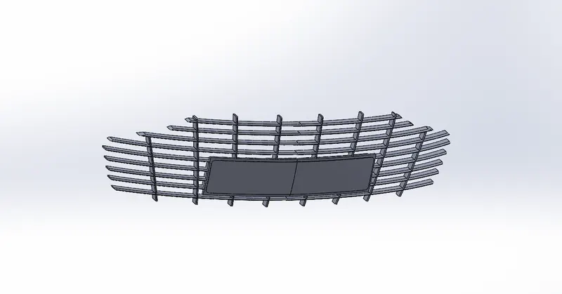
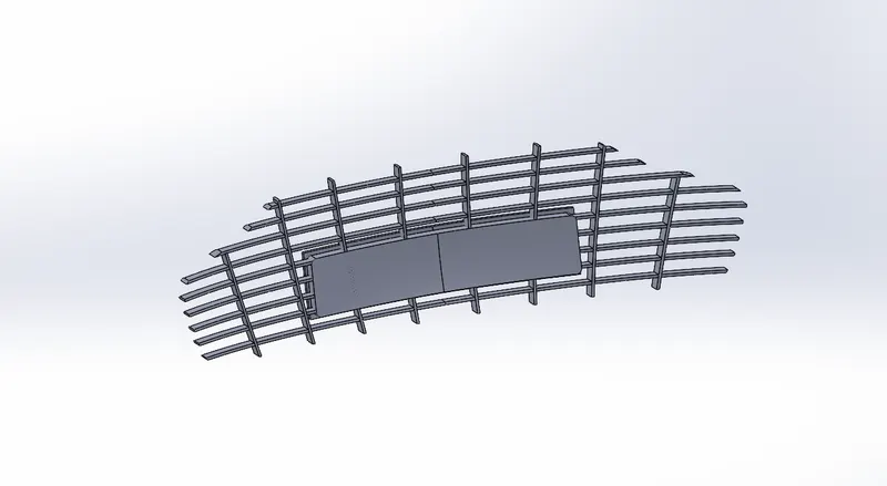
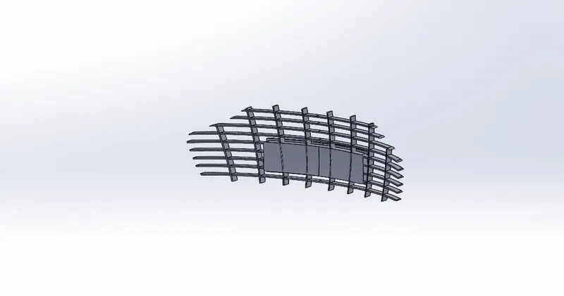
Grills:
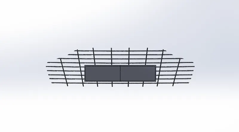
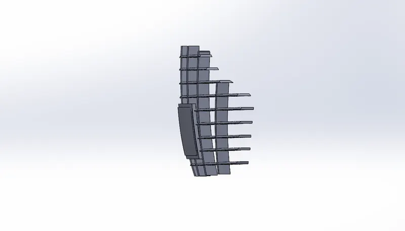
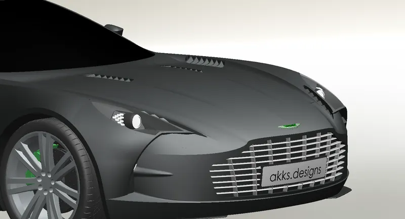
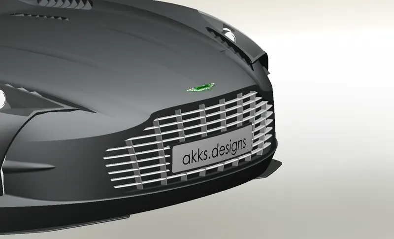
A grille covers an opening in the body of a vehicle to allow air to enter or exit.Most vehicles feature a grille at the front of the vehicle to protect the radiator and engine.
TOOLS USED
Sketch Tools:
- Spline
- Line
- Circle
- Offset Entities
- Convert Entities
Surface Tools:
- Surface knit
- Surface Extend
- Offset Surface
- Move/ copy bod
Feature Tools:
- Trim
- Fillet
- Extrude Cut
- Combine
- Extrude Boss/ Base
Views:
Isometic:
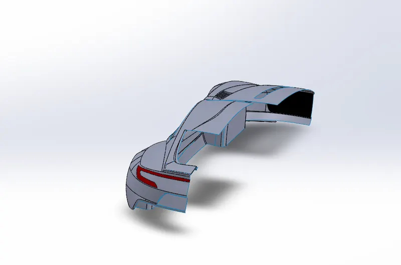
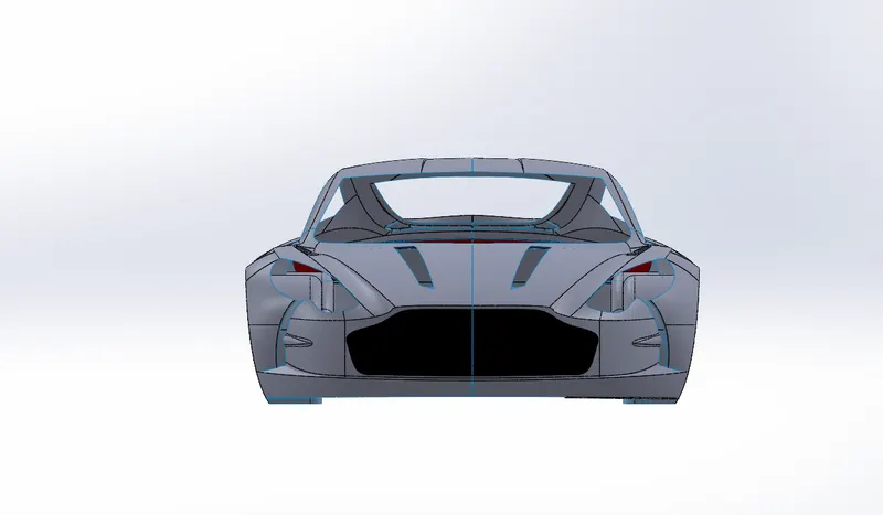
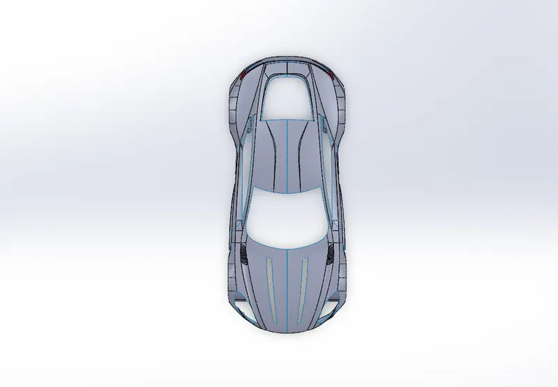
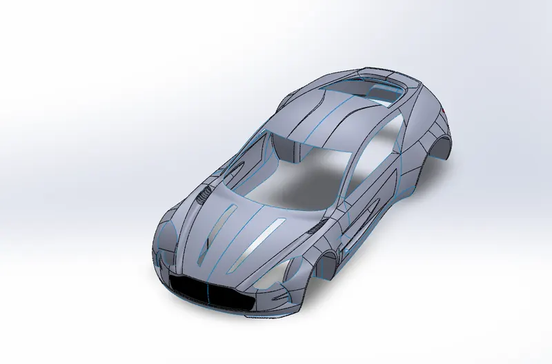
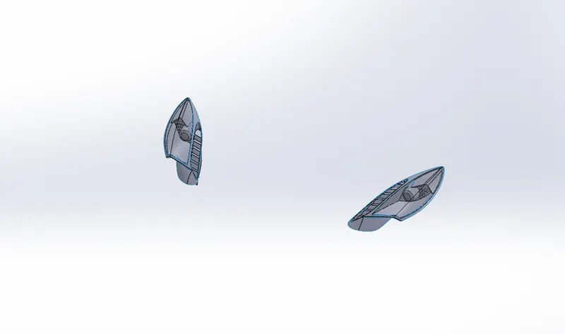
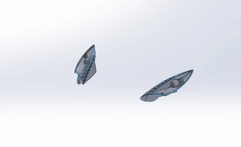
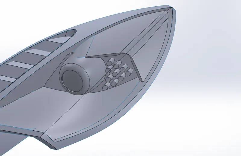
Light:
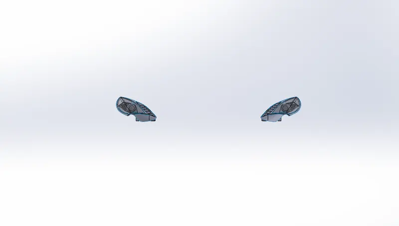
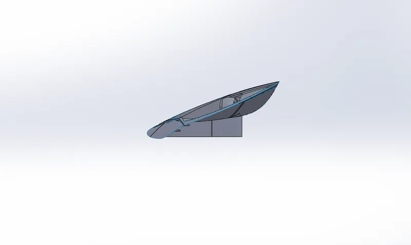
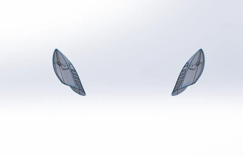
A headlamp is a lamp attached to the front of a vehicle to illuminate the road ahead.Headlamps are also often called headlights, but in the most precise usage, headlamp is the term for the device itself and headlight is the term for the beam of light produced and distributed by the device.The lighting system of a motor vehicle consists of lighting and signalling devices mounted or integrated at the front, rear, sides, and in some cases the top of a motor vehicle.hese light the roadway ahead for the driver and increase the visibility of the vehicle, allowing other drivers and pedestrians to see a vehicle's presence, position, size, direction of travel, and the driver's intentions regarding direction and speed of travel.
TOOLS USED
Sketch Tools:
- Spline
- Line
- Circle
- Offset Entities
- Convert Entities
- 3D sketch
Surface Tools:
- Surface Trim
- Surface Extrude
- Boundary Surface
- Surface Fill
- Surface knit
- Ruled Surface
- Offset Surface
- Surface Extend
- Move/ copy body
- Cut with Surface
- Thicken
Feature Tools:
- Projected Curve
- Reference Plane
- Trim
- Split
- Fillet
- Linear Pattern
- Extrude Cut
- Combine
- Mirror
- Revolve
- Extrude Boss/Base
Views:
Isometric:
Wheel:
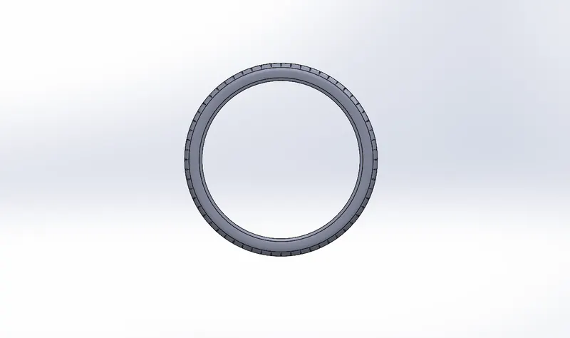
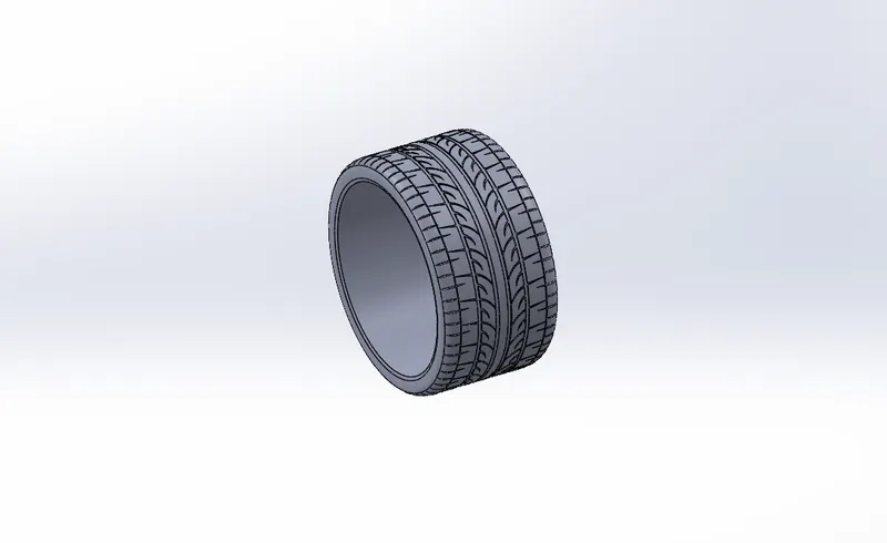
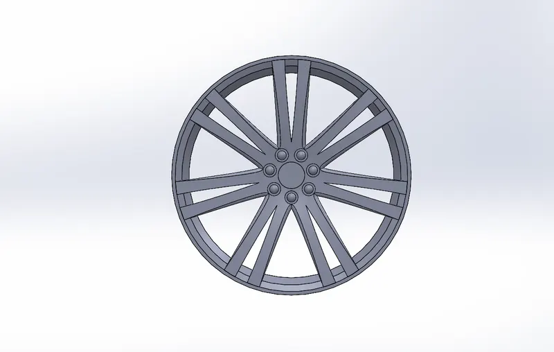
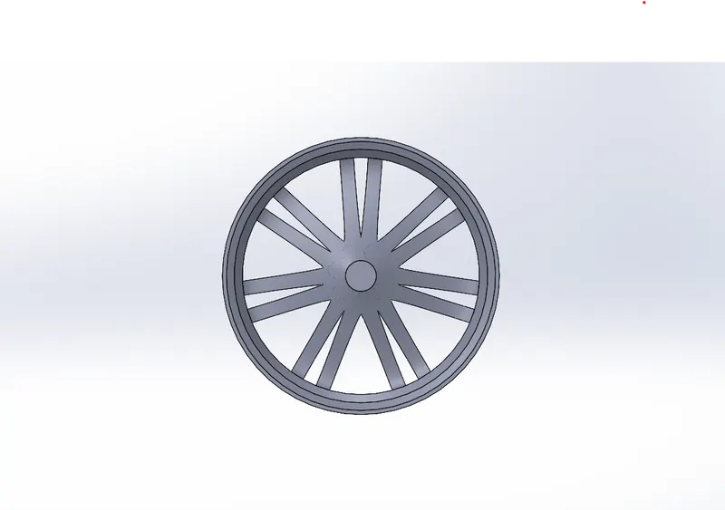
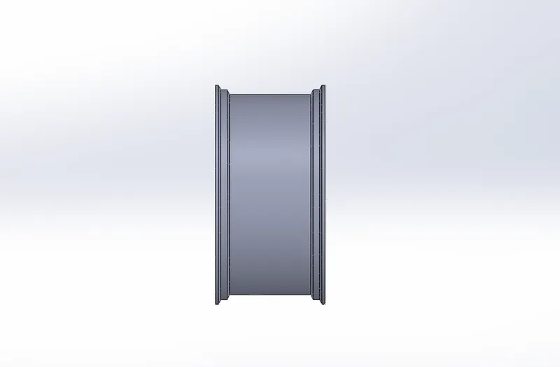
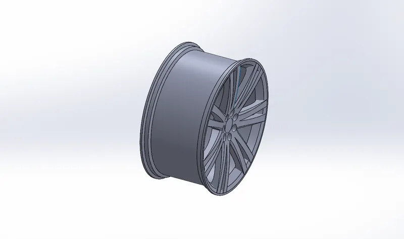
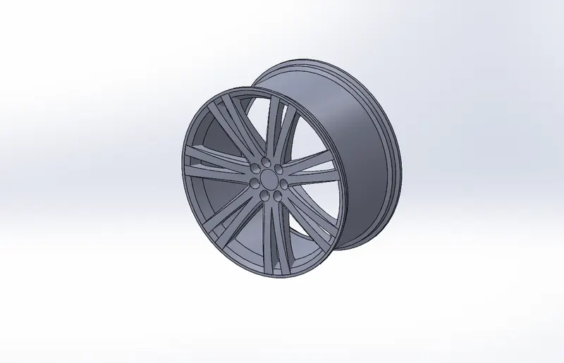
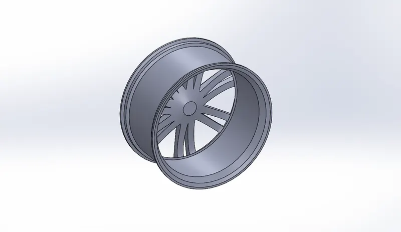
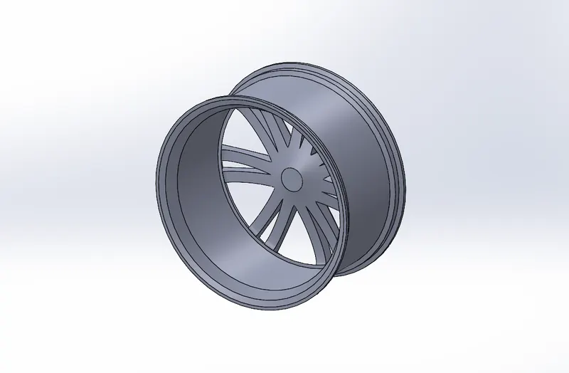
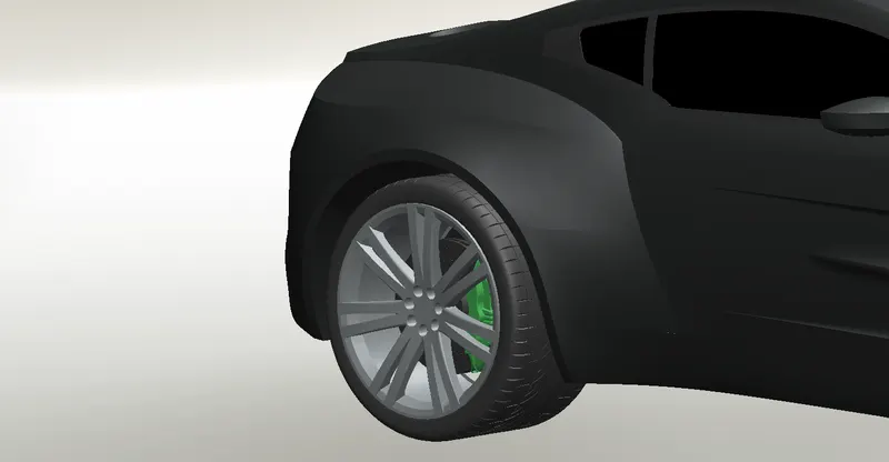
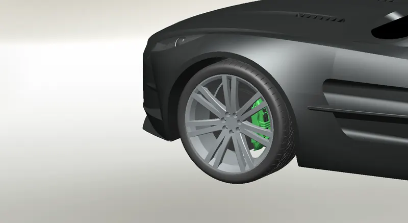
Wheel consists of rim,tyre and brake which make it the component that makes the connection between the car and the ground.The rim is an important strength component which ensures safe load carrying capacity of the car.It should have enough compressive strength and able to absorb shocks and impacts. The tyres are the main contact surface to the ground.The wheel also houses a disc brake rotor and its caliper. The designing of front and rearTo begin a revolved part is created on the right plane which is the rim now the spokes are sketched on the right plane and extruded wheels are similar the differences is in the size of the wheels.
Tools Used
Sketch Tools:
- 3 point arc
- spline
- Circle
- Trim
- Rectangle
- Fillet
Feature Tools:
- Revolve
- Extruded Boss/base
- Circular pattern
- Chamfer
- Appearance
- Revolve Cut
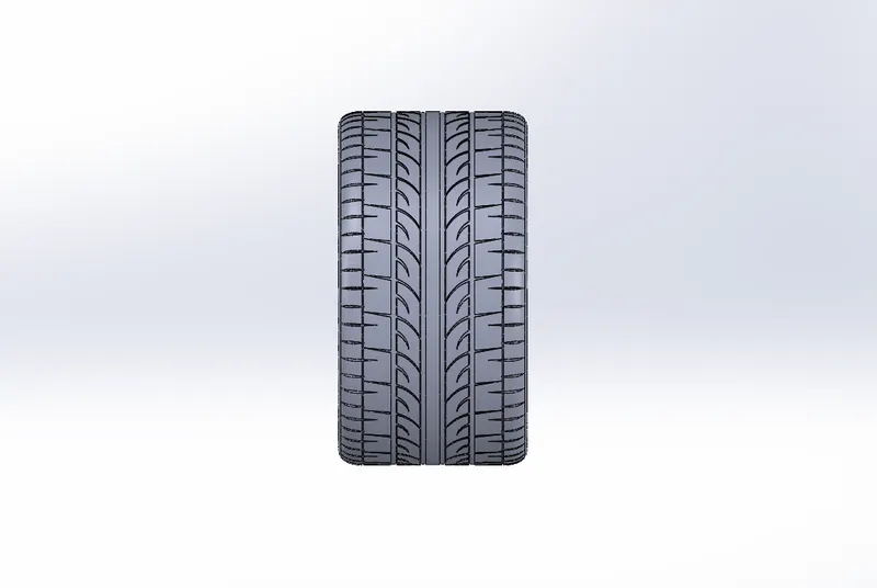
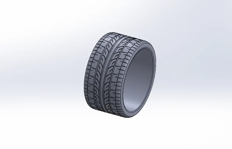
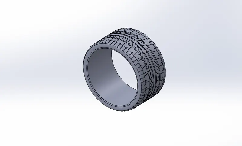
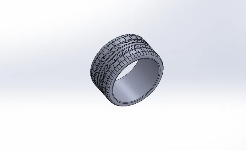
Tyre:
Views:
Isometric:
Alloy:
View:
Isometric:
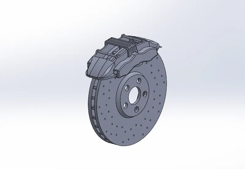
Disc Brake:-
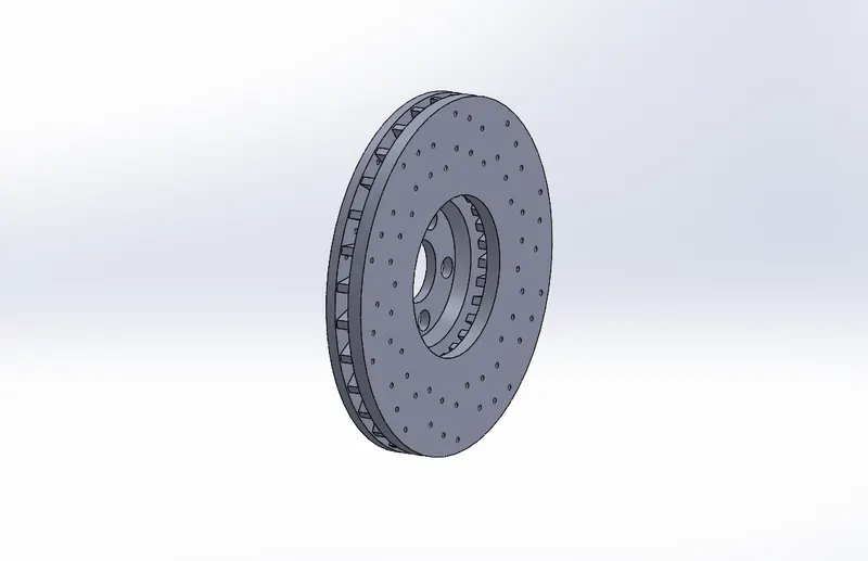
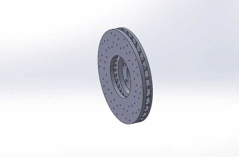
Disc brake is a new braking system. This breaking system has very good gripping and works very precisely It is used in high-speed vehicles because the disc brake works very quickly relative to the drum brake.Sketch is very simple ,start sketch on top plane and apply to revolve boss base ,Just you can see only a few steps are in my design tree all are very simple.
Tools Used
Sketch Tools:
- Circle
- Fillet
Feature Tools:
- Revolve
- Extruded Boss/base
- Circular pattern
- Chamfer
- Appearance
Views:
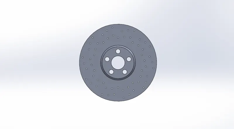
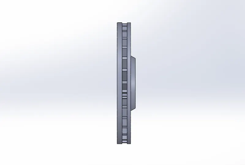
Isometric:
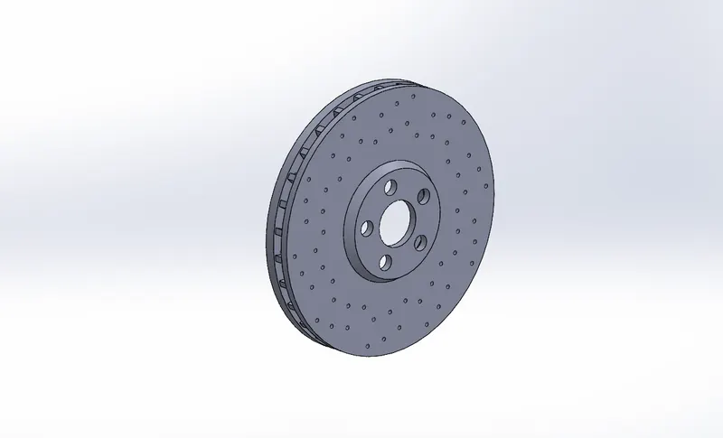
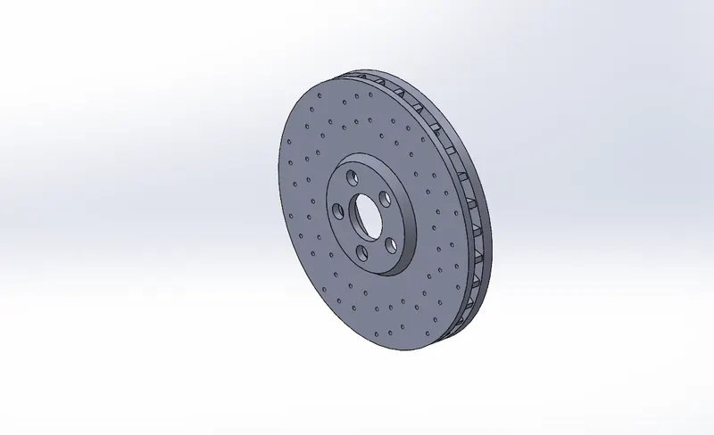
Caliper:
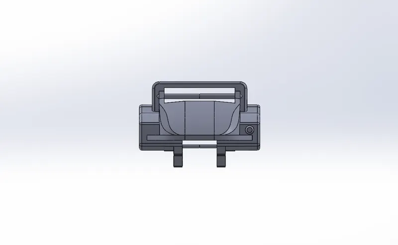
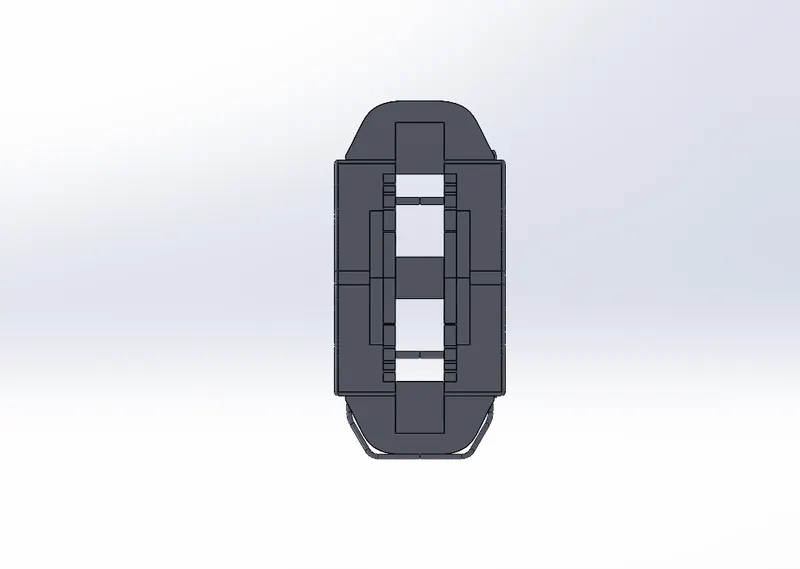
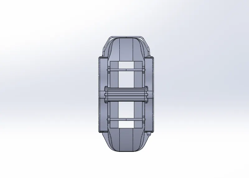
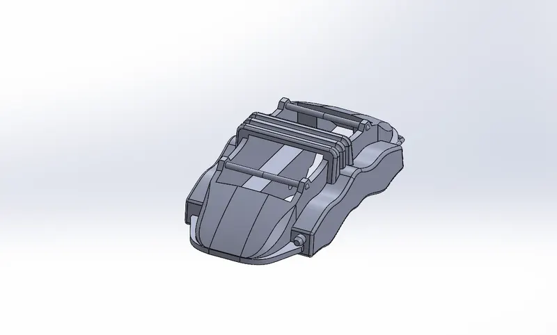
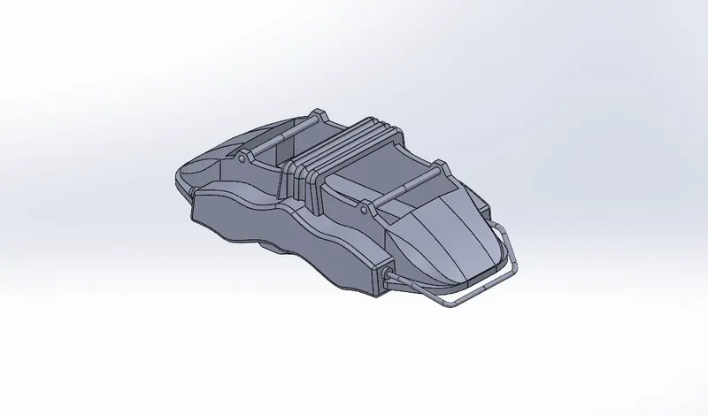
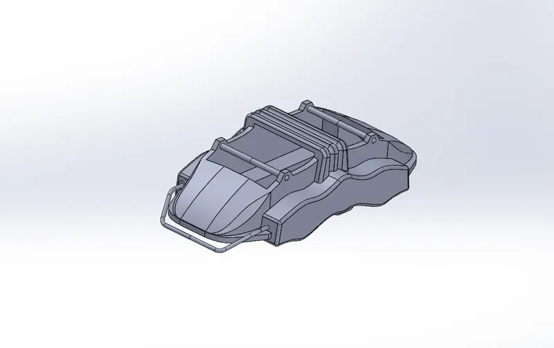
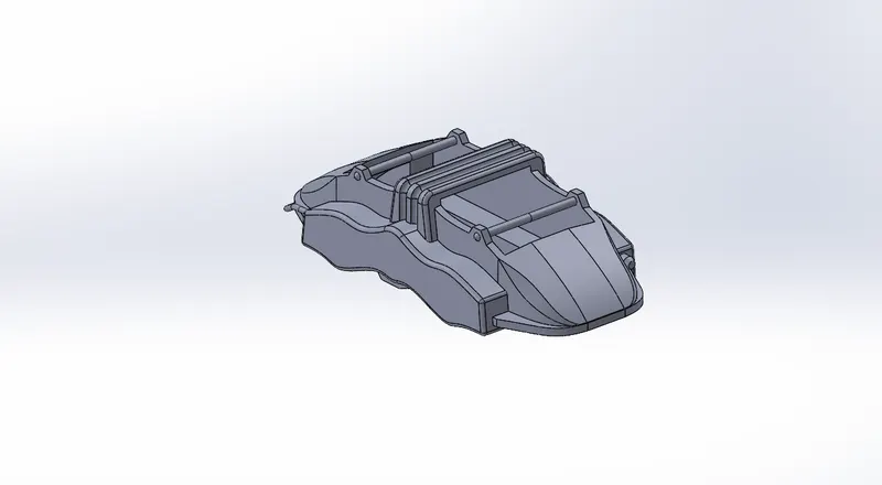
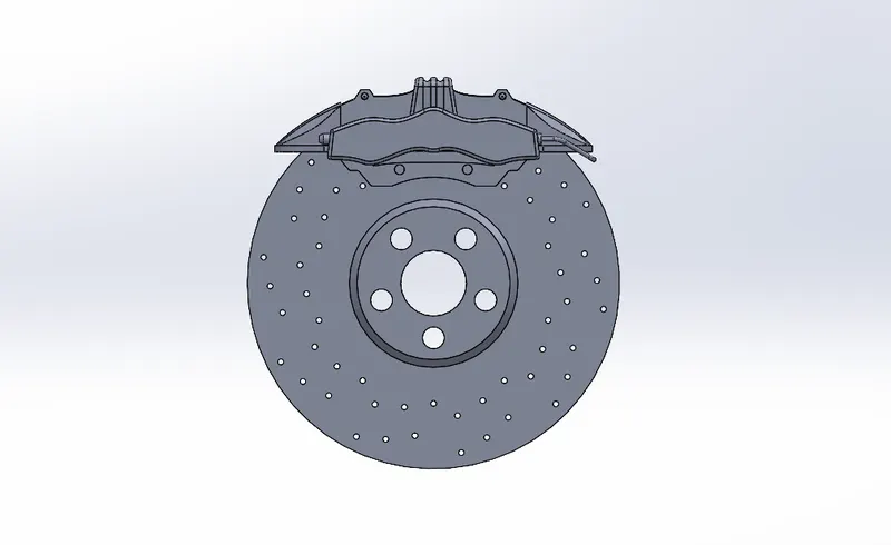
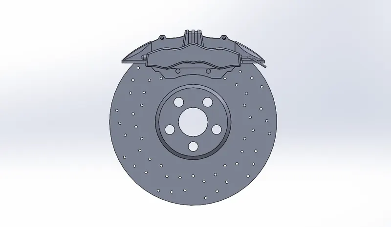
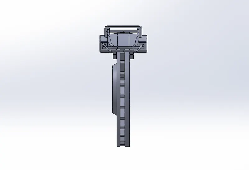
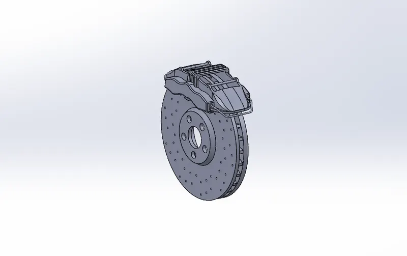
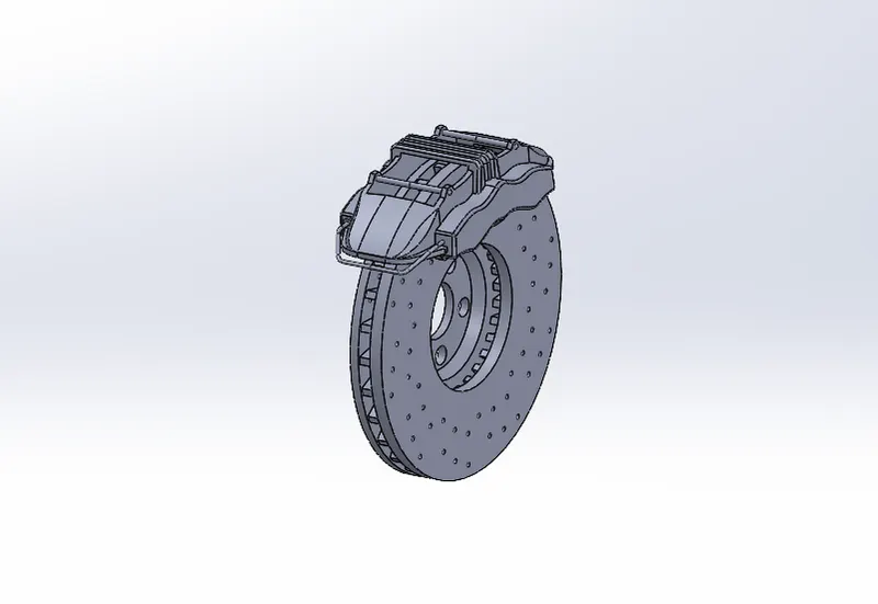
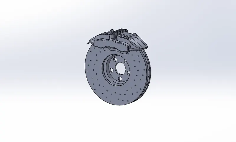
Caliper is a device that is used in a disc brake for griping the disc plate as above drawn.The sketch of the caliper is also easy First, insert a blueprint of the caliper on the top plane Just sketched according to the blueprint add extrude boss base. Here is an amazing thing is you have to create just a quarter part of the caliper and after completing the part simply mirrored the part two times the first time make it half and the second times make it complete.
Views:

Isometric:
Emblem:
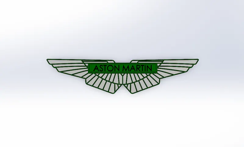
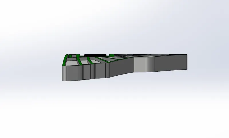
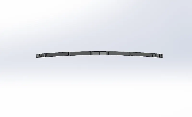
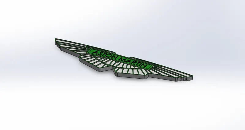
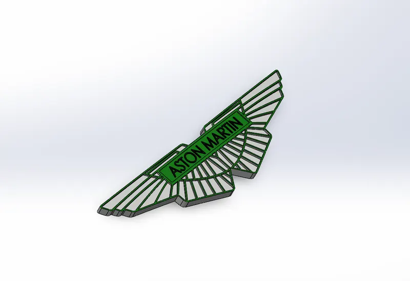
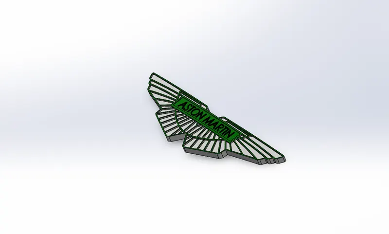
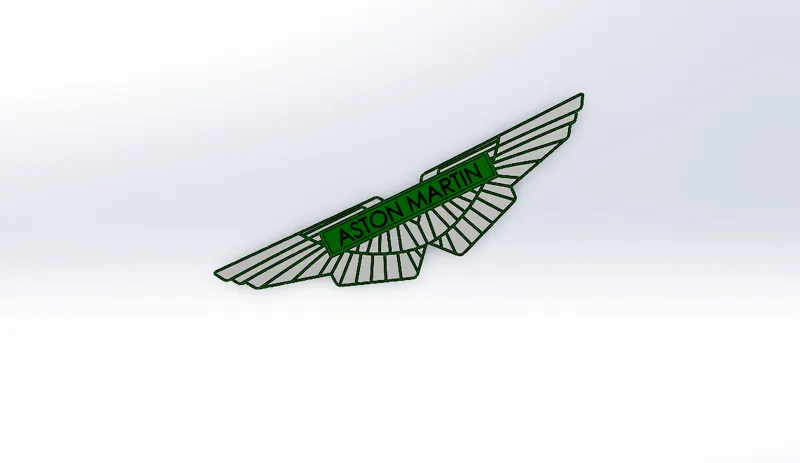
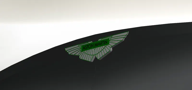
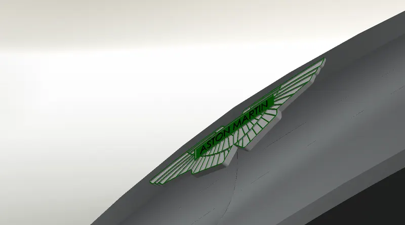
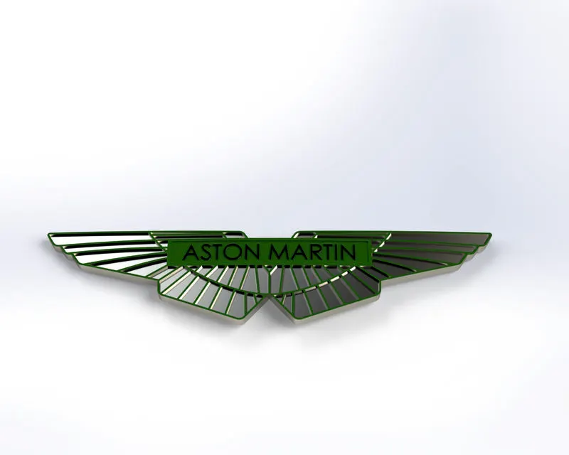
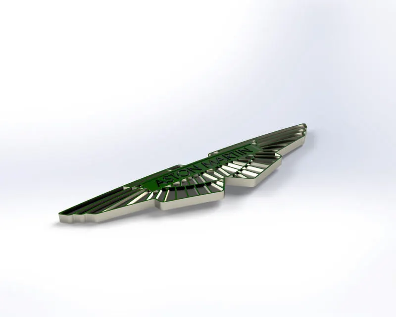
Aston Martin has also a special logo Aston Martin is a very big brand in the field of the Automotive industry. So emblem is very important and its sketch is not much tough.First of all, insert the blueprint of the emblem on the front plane. start sketch on the front plane .Apply to extrude boss base.cut extra extruded par by extrude cut.This part was entirely made using solid modelling.Extrude boss, extrude cut, mirror, combine etc are used.
Views:
Isometric:
Sub-assembly of Caliper Assembly
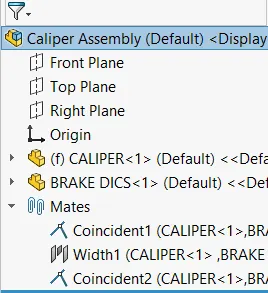
Sub-assembly of Brake Disc consists of a disc and a caliper.Both the parts are assembled using concentric and centered width mates.
Mates:
View:
Isometric:
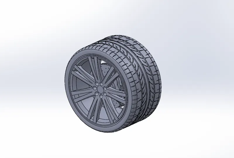
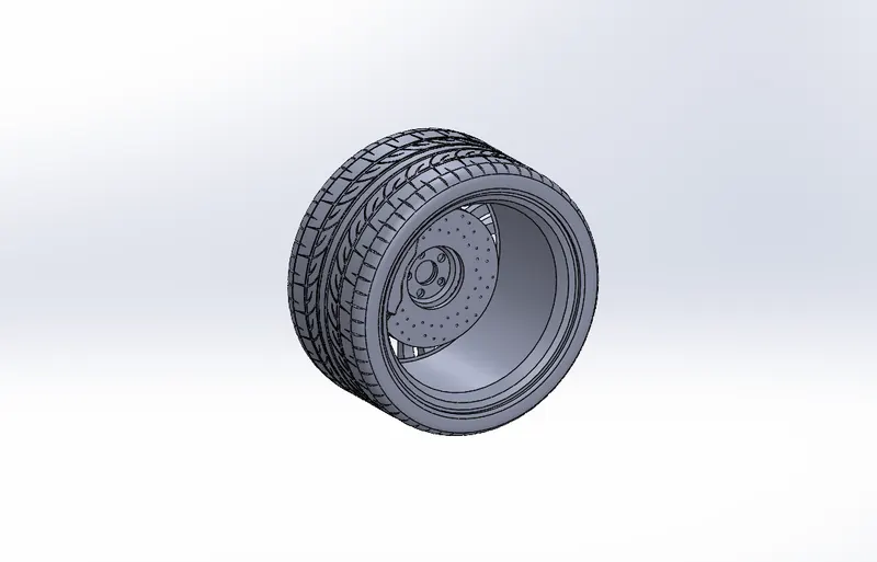
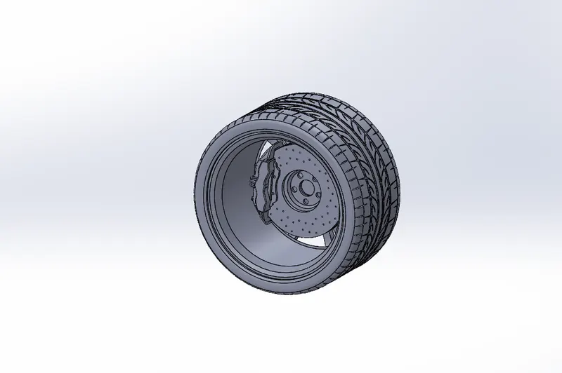
Sub-assembly of Wheel
Sub-assembly of the front wheel and the rear wheel is the same. This sub-assembly consists of rim, tire, and sub-assembly of the brake disc.All the parts are assembled using concentric,coincident and distance mates.
Mates:
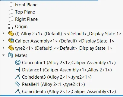
Views:
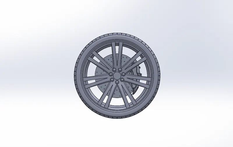
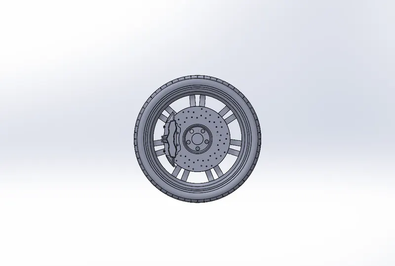
Isometric:
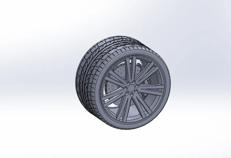
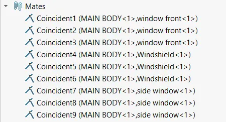
ASSEMBLY OF MAIN BOGY WITH DOOR,WINDOWS,WINDSHIELD
Mates:
Views:
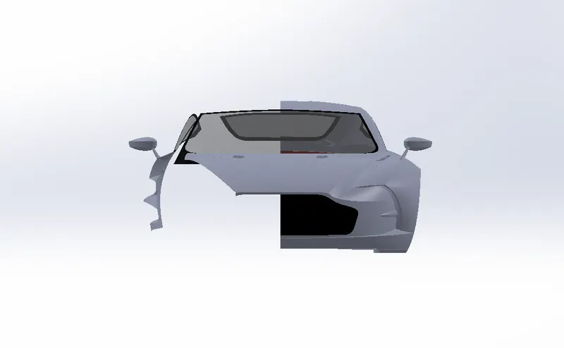
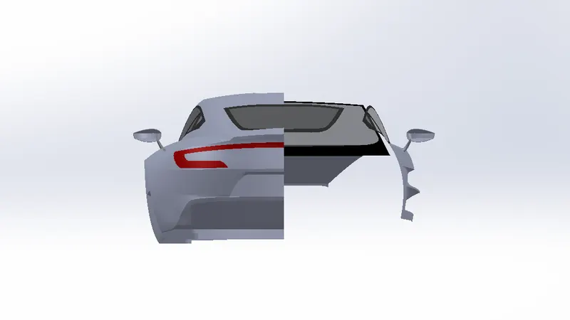
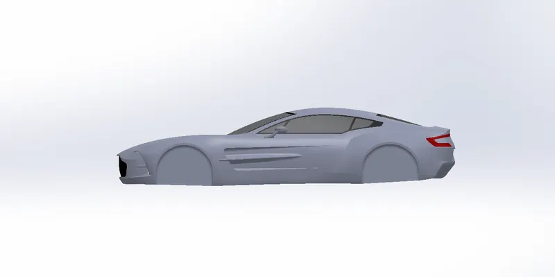
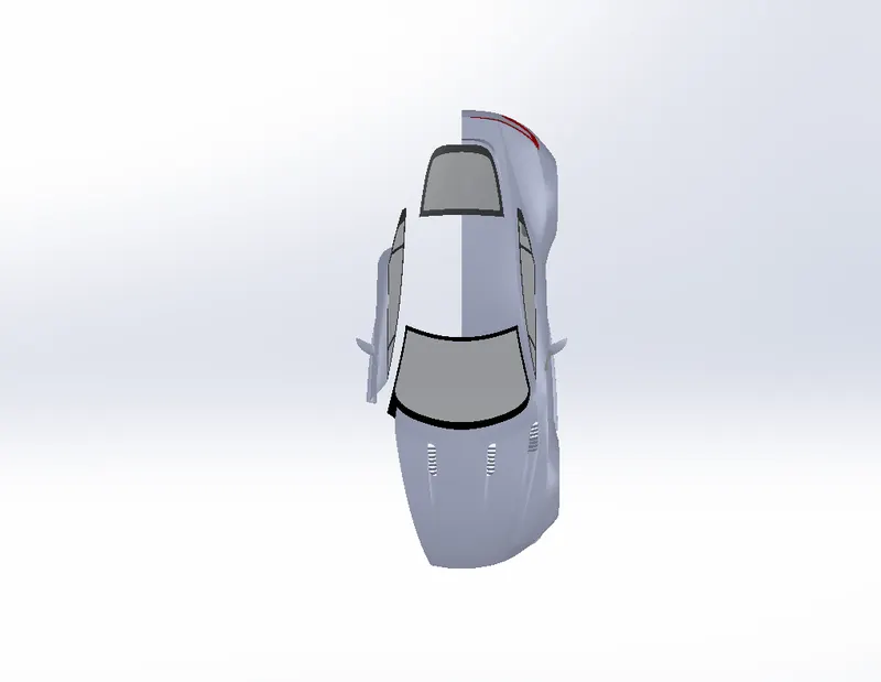
Isometric:
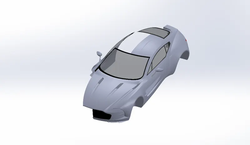
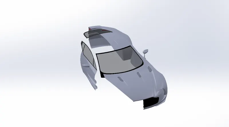
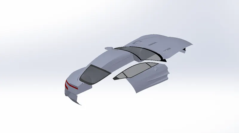
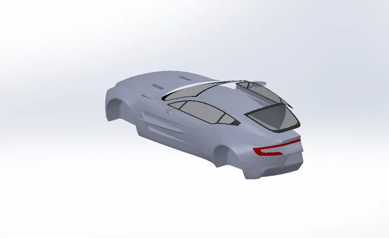
Assembly of Aston Martin One-77
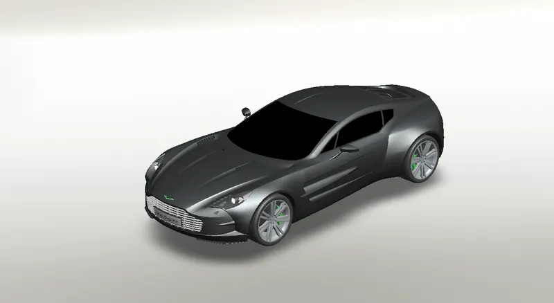
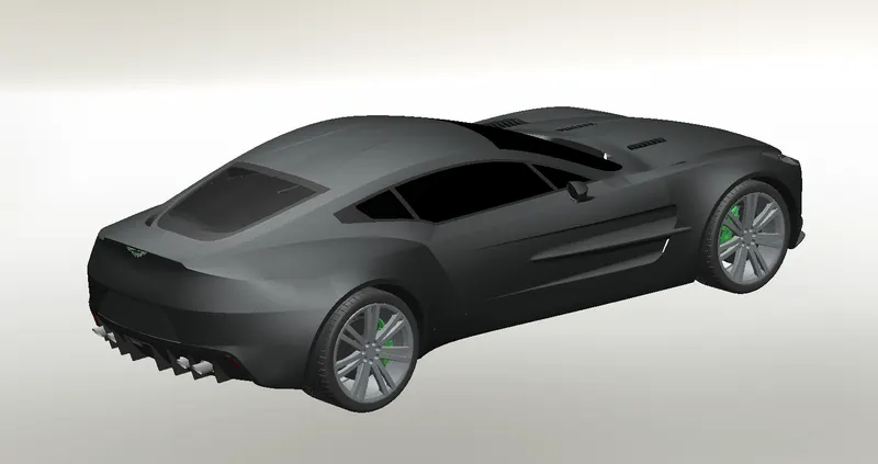
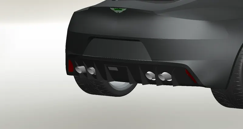
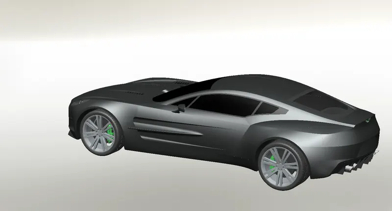
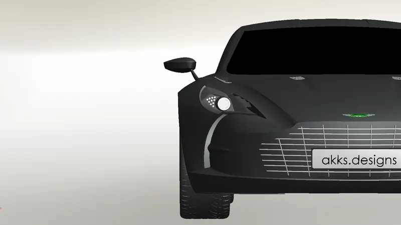
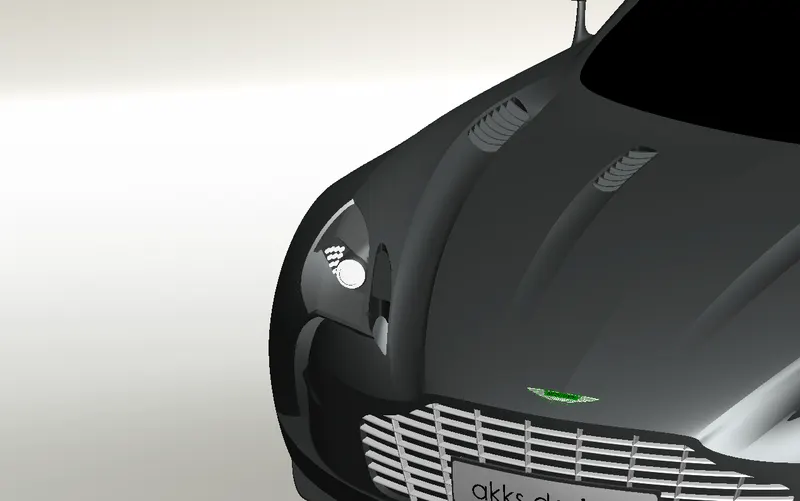
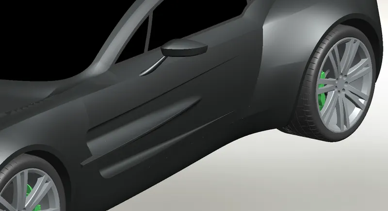
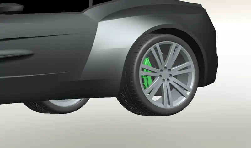
After completion of all the sub-assemblies, we proceeded to the final assembly of the car.Final assembly of the Aston Martin One-77 consists of the grille, hood, windshield, windows, doors, rear window, rear bumper, emblem and sub-assemblies of front and rear wheel.Bottom- Up design is the traditional method. You will first design and model the part individually, then insert them into an assembly and use mates to position parts. To change parts you must edit them individually. These changes are then seen in assembly. If there is any interference in the assembly or changes required in the assembly you need to modify the components individually either in the assembly level or in the part document level.
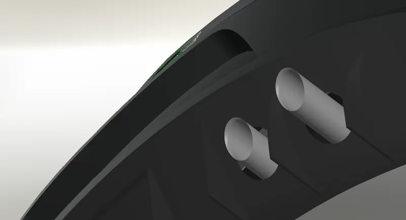
After making all the parts the most important part of assembling the entire car to a single file begins. To start with bringing the body first and using its plane and geometry as a base for the entire solid assembly, the second part we bring in is the doors. The planes of doors made coincident mate with the curresponding planes of body.After that we bring hood, windows, front and rear windshields, grille and rear bumper made coincident mates with the planes of body. For front and rear wheel , we use distance mates of 93.3 mm for front wheel and 92.2 mm for back wheels from the front plane.Finally the Aston Martin emblem fixed with the body.
Views:
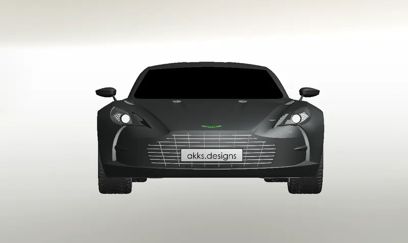
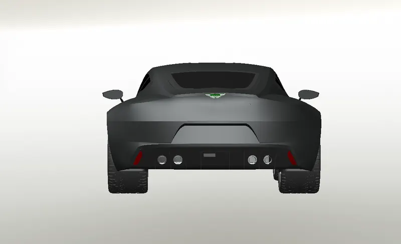
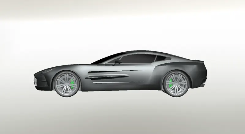
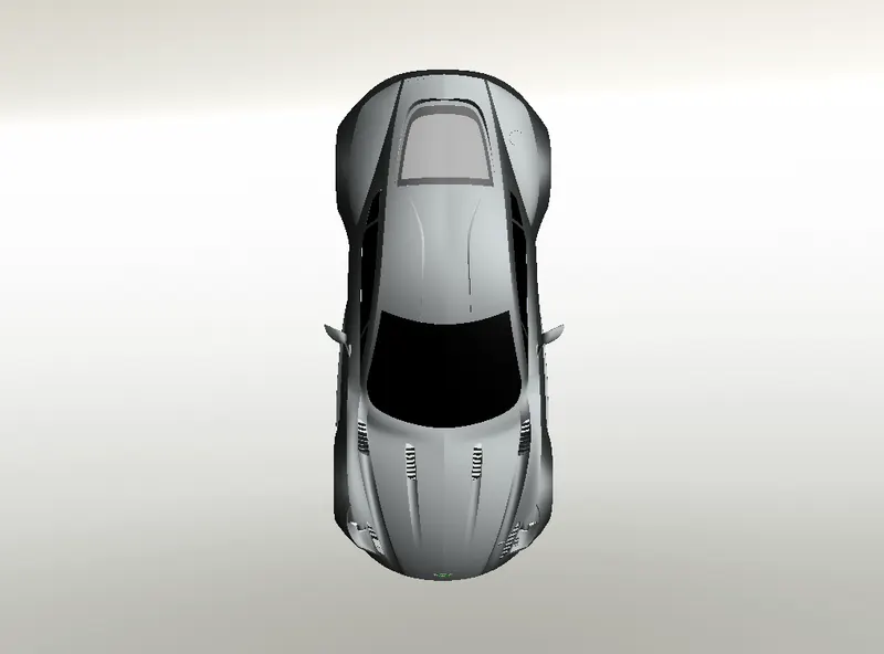
Isometric:
RENDERED
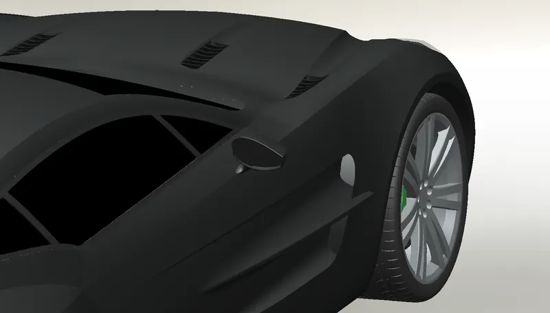
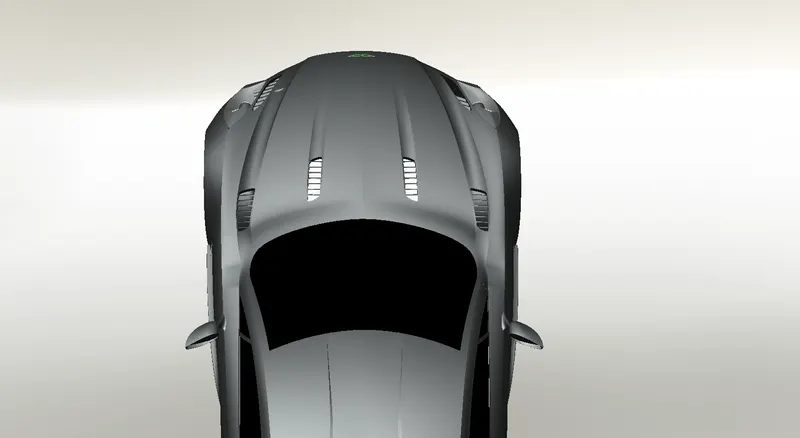
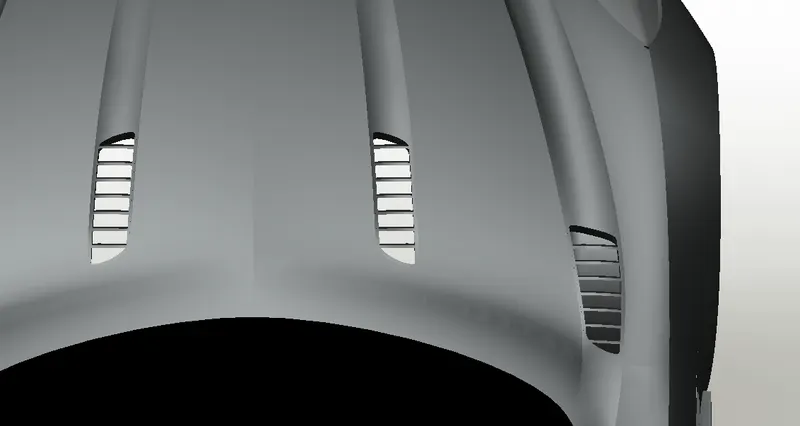
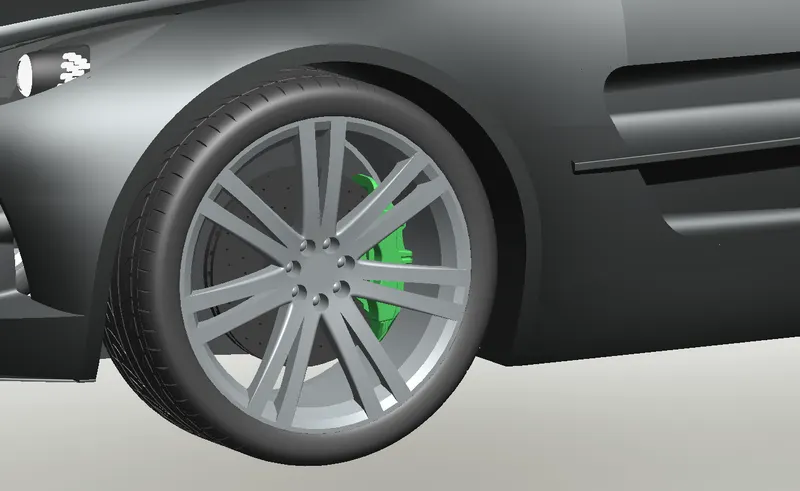
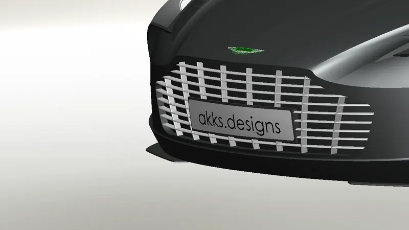
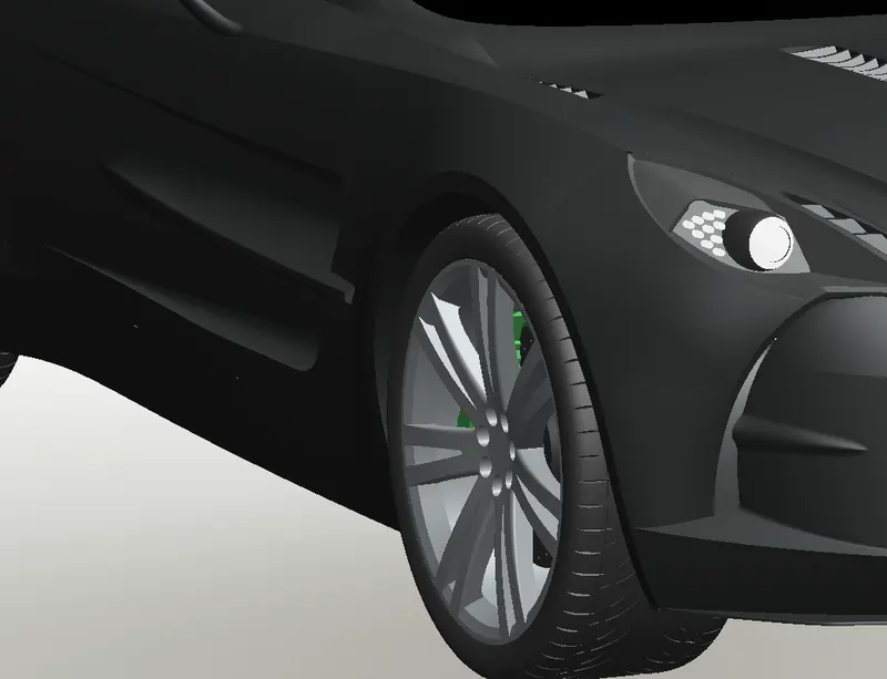
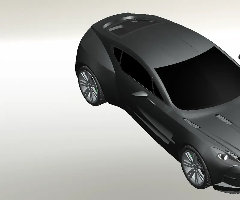
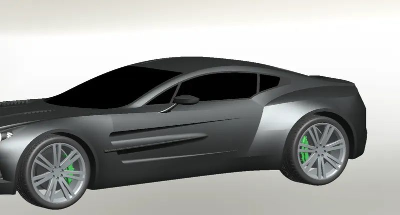
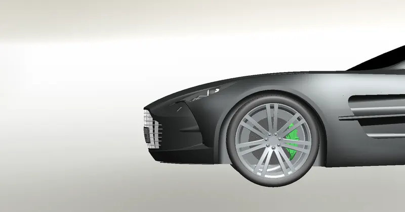
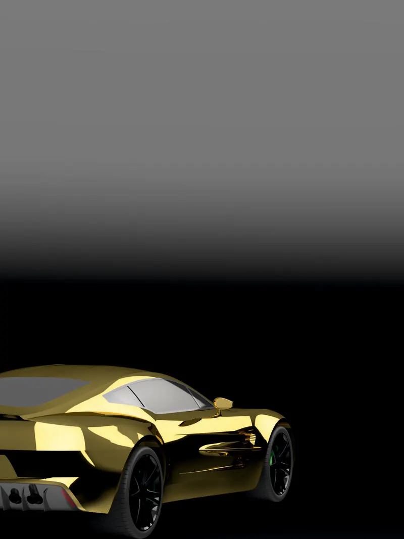
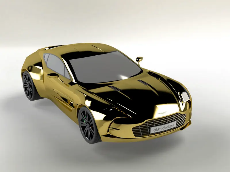
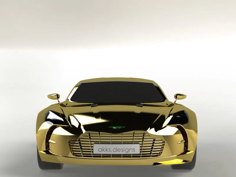
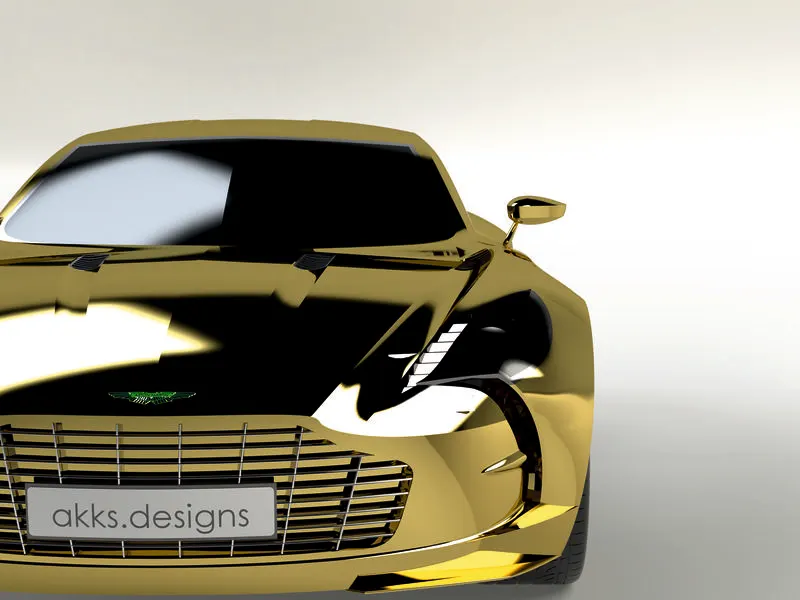
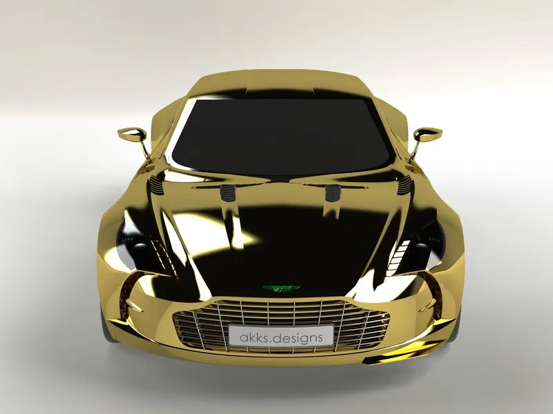
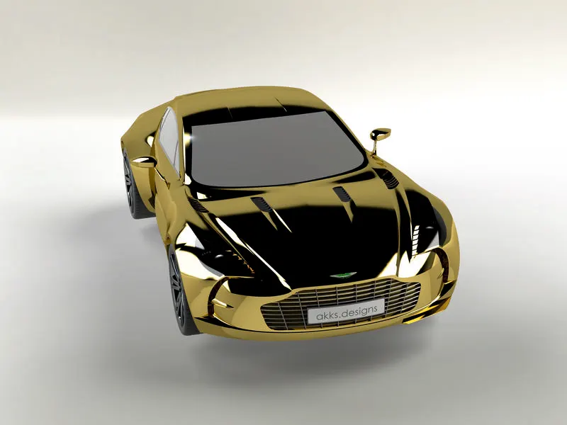
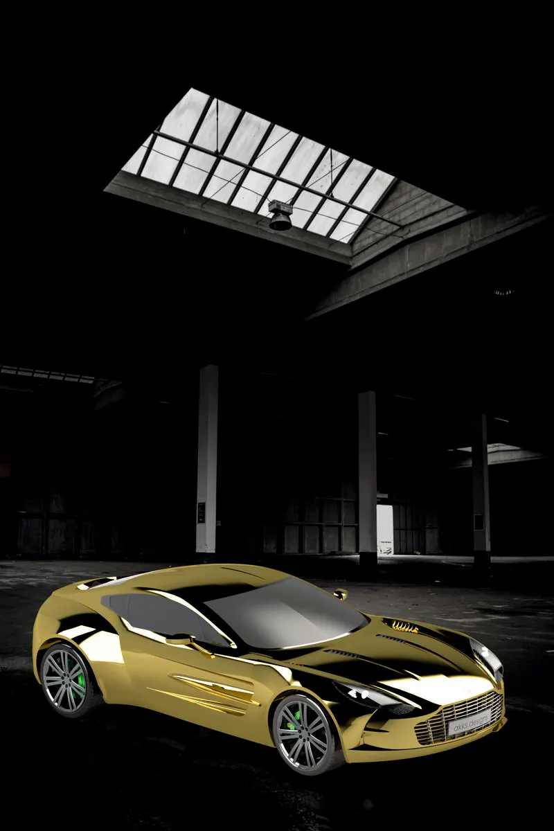
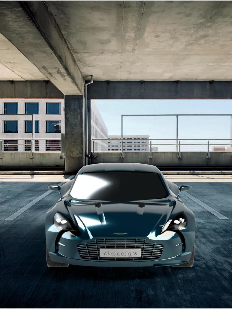
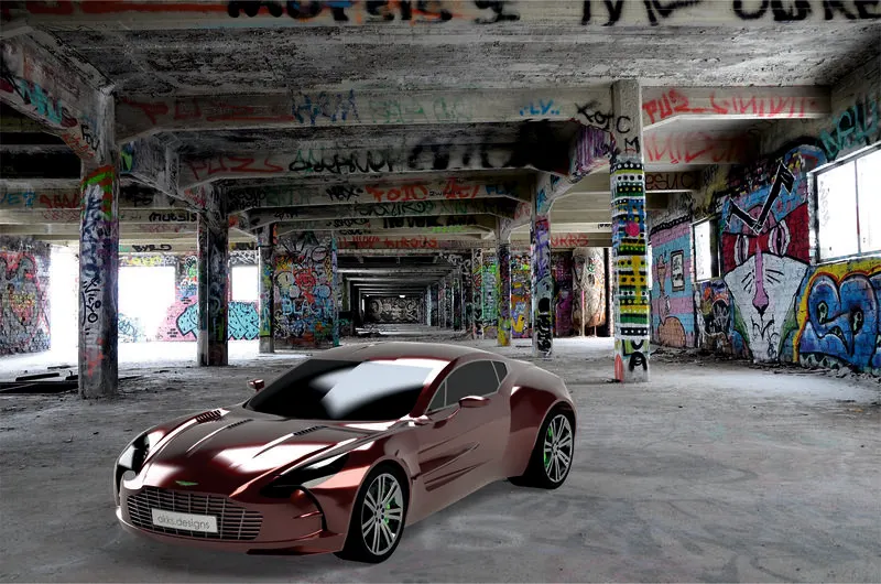
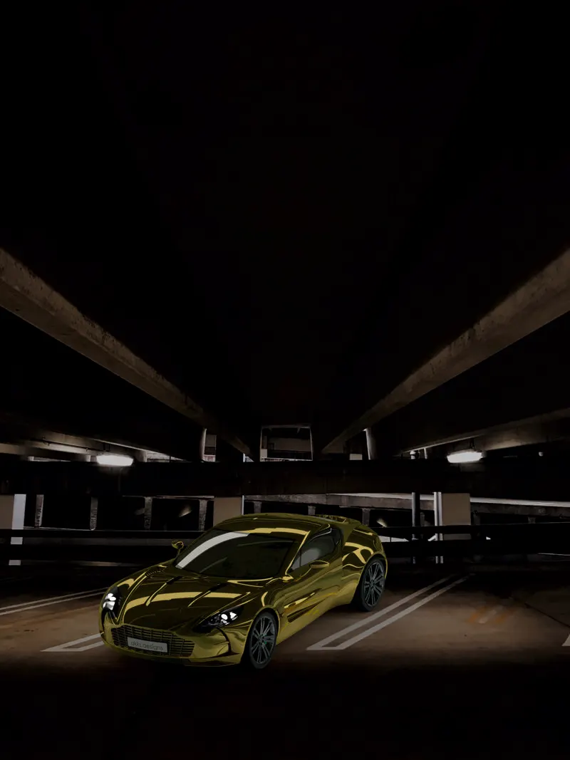
Rendering is the process of turning information from a 3d model into a 2d image.3d rendering can be used to create a variety of images, from intentionally nonrealistic to what is called photorealistic. Behind every 3d rendered image, realistic or not is a rendering process that starts with 3d modeling.Rendering of the assembly is done to make good quality 2D images for the purpose of advertising and promotion of the products before selling it to the customers. Photorealistic rendering creates high quality images or motion graphics if available so as to look appealing in various environments and backdrops.We try to make it more realistic by giving it a camera view setting the desired lights and the focal distance creating the angle of the view and saving the camera angle which gave a realistic view to the car.Now we take our assembly file into solid works visualize where we start making the product more and more realistic with adding the background changing the and adjusting the brightness, shadow density and gamma levels according to the different requirements of the different backgrounds changing the color of the model and checking what suits the best with which background until we get the desired and astonishing product ready.


CONCLUSION
- The parts are sketched and modelled in the SOLDWORKS.
- The modeled parts are assembled with possible mates in to the main assembly
- The decals are applied to faces of parts.
- The realistic image was rendered with the use of the Solidworks visualize.
REFERENCE
- skill-lync.com