Project 1

OBJECTIVE:-
Analyse the simulation on two leaf spring model of different material for finding the failure and summerise those thing for improvement.
Because Leaf springs are an integral part of your vehicle's suspension system. They are installed to help support the entire weight of your car or truck. Leaf springs also help to maintain the tyres grip on the road and regulate the wheelbase lengths when it is speeding up or slowing down .
Abstract -
The function of a suspension system is toabsorb the bumps in the road and thus maximizing the
overall performance of a vehicle. A type of suspensionsystem, the Leaf Spring suspension system, is mainly used in
heavy commercial vehicles at present. It is crucial to do aproper fail-proof analysis of these components prior to
manufacturing and use. The components are designed andassembled in CAD modelling software. For modeling
purposes, Solidworks software is used. For the purpose ofmeshing software, hypermesh is used and ANSYS for
performing analysis.
2. LEAF SPRING
A multi-leaf or laminated spring consists of a series of flat plates, usually of semi-elliptical shape .
The flat plates, called leaves, have varyinglengths. The leaves are held together by means of U-bolts
and a center clip. The longest leaf, called the master leaf, is bent at the two ends to form spring eyes. Two bolts are
inserted through these eyes to fix the leaf spring to theautomobile body. The leaves are held together by means of
two U-bolts and a center clip. Rebound clips are providedto keep the leaves in alignment and prevent lateral shifting
2. Underslung- In underslung the leaf springs are mounted below the axle. In this type of attachment, the
U-Bolts carry effective loadA vehicle can be equipped with either overslungor underslung depending upon the requirement. The underslung setup helps to reduce the deck height of the vehicle which can be advantageous in terms of providing
load stability, but on the other hand, having an underslung reduces deck clearance which can expose the vehicle to
contact with objects lying on the road/any boulders, etc. Whereas on the other hand, overslung setup helps
increase the deck height of the vehicle which in result provides more clearance to the deck.
3. LEAF SPRING MODEL
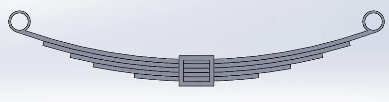
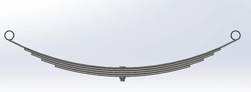
The following leaf spring model assembly was built in Solidworks
Labeled model
1 - Eye
2 - Rebound Clip
3 - Bolt
4 - Master leaf
5,6,7 - Graduated-Length leave
Units
|
Material Properties
|
Properties |
||||||||||||||||||||
|
|
Properties |
||||||||||||||||||||
|
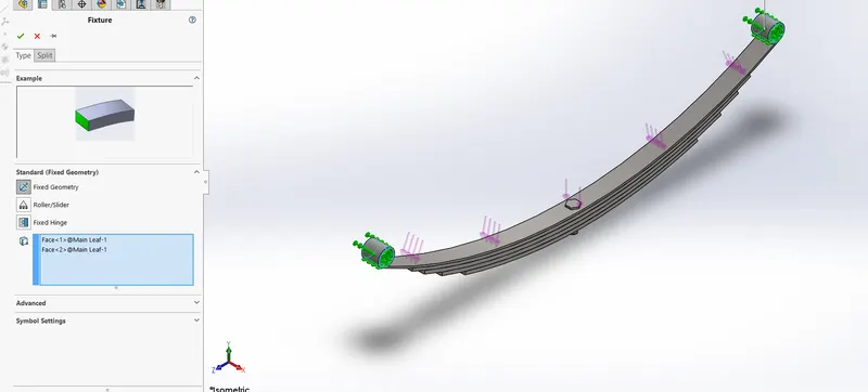
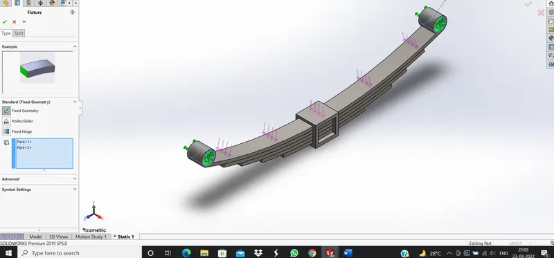
Boundary Condition
4. MESHING
For meshing purposes, Hypermesh software was used to ensure proper meshing in critical areas. The type
used was 2D mesh. It is used as two of the dimensions are very large in comparison to the third dimension.
It is necessary to ensure good quality of the mesh, especially in critical regions to ensure proper results while
performing analysis. For example, it is necessary to have a quad-type mesh near-circular periphery.
The meshing was performed in the following steps:
(i) At first critical regions were identified. the critical regions noted were - eye section of the master leaf and
bolt section and the region surrounding the bolt in the leaves. The face of the part was then splitted in a suitable
manner.
(ii) After splitting the faces, meshing was done on the faces of the suitable element size.
(iii) For meshing at the critical portion around the eye ofthe leaf, a washer of suitable dimension and a 2D mesh of
type quad was done
(iv) For the base plate region we split the area around thehole by adding nodes and creating a square region around
the hole.
This square region was created by transmitting the nodesat eight different locations as shown in the
These nodes were joined by lines. The regions betweenthis node were split using surface edit and then trim with
lines command. We started by meshing a single quarterregion and then optimizing the mesh in it. This generated
mesh was then transmitted to other similar regions andthe regions surrounding it were meshed by using auto
meshing using proper mesh size. Further, this entire meshwas transmitted to another side of the base plat.
Mesh information
|
Mesh type |
Solid Mesh |
|
Mesher Used: |
Standard mesh |
|
Automatic Transition: |
Off |
|
Include Mesh Auto Loops: |
Off |
|
Jacobian points |
4 Points |
|
Element Size |
10.0401 mm |
|
Tolerance |
0.502005 mm |
|
Mesh Quality Plot |
High |
|
Remesh failed parts with incompatible mesh |
Off |
Mesh information - Details
|
Total Nodes |
47505 |
|
Total Elements |
26713 |
|
Maximum Aspect Ratio |
104.26 |
|
% of elements with Aspect Ratio < 3 |
88.2 |
|
% of elements with Aspect Ratio > 10 |
0.824 |
|
% of distorted elements(Jacobian) |
0 |
|
Time to complete mesh(hh;mm;ss): |
00:00:24 |
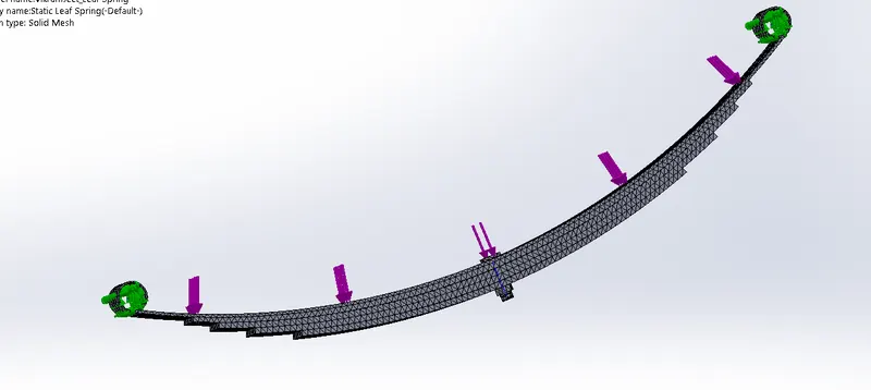
|
Mesh type |
Solid Mesh |
|
Mesher Used: |
Standard mesh |
|
Automatic Transition: |
Off |
|
Include Mesh Auto Loops: |
Off |
|
Jacobian points |
4 Points |
|
Element Size |
12 mm |
|
Tolerance |
0.6 mm |
|
Mesh Quality Plot |
High |
Mesh information - Details
|
Total Nodes |
31368 |
|
Total Elements |
18702 |
|
Maximum Aspect Ratio |
36.955 |
|
% of elements with Aspect Ratio < 3 |
88 |
|
% of elements with Aspect Ratio > 10 |
0.529 |
|
% of distorted elements(Jacobian) |
0 |
|
Time to complete mesh(hh;mm;ss): |
00:00:07 |
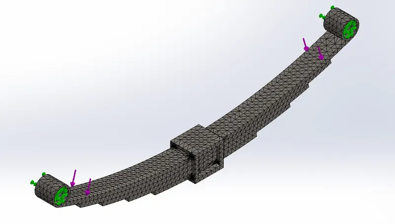
5. ANALYSIS
The static analysis was done using ANSYnSsoftware. For this study, we used static structural analysis.
The material used to perform the analysis.
Stress model 1
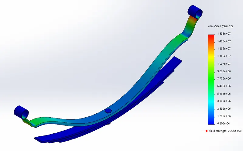
|
Name |
Type |
Min |
Max |
|
Stress1 |
VON: von Mises Stress |
6.206e-04 N/m^2 Node: 29573 |
1.555e+07 N/m^2 Node: 46424 |
Displacement
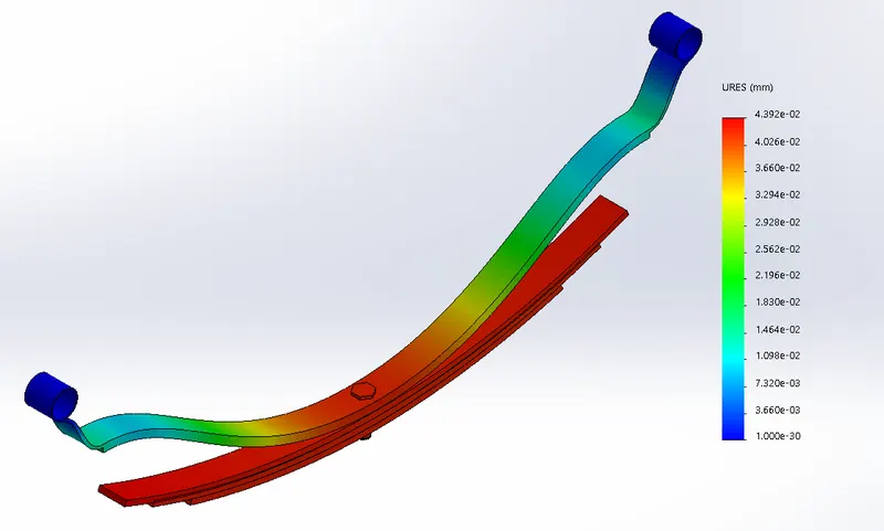
|
Name |
Type |
Min |
Max |
|
Displacement1 |
URES: Resultant Displacement |
0.000e+00 mm Node: 39514 |
4.392e-02 mm Node: 15458 |
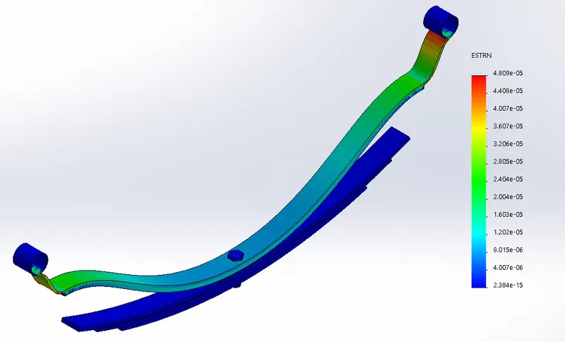
Strain
|
Name |
Type |
Min |
Max |
|
Strain1 |
ESTRN: Equivalent Strain |
2.384e-15 Element: 16548 |
4.809e-05 Element: 22698 |
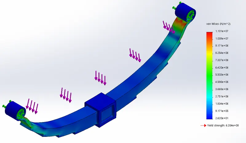
Stress model 2
|
Name |
Type |
Min |
Max |
|
Stress1 |
VON: von Mises Stress |
2.620e+01 N/m^2 Node: 5495 |
1.101e+07 N/m^2 Node: 7688 |
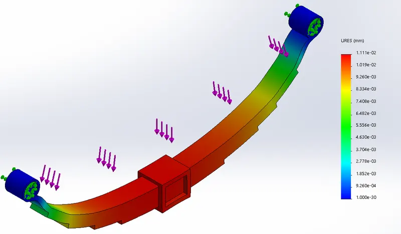
Displacement
|
Name |
Type |
Min |
Max |
|
Displacement1 |
URES: Resultant Displacement |
0.000e+00 mm Node: 2736 |
1.111e-02 mm Node: 10312 |
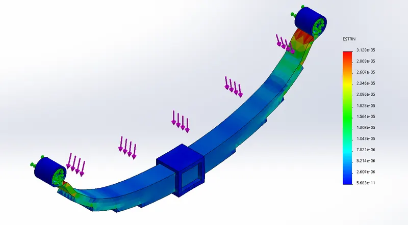
Strain
|
Name |
Type |
Min |
Max |
|
Strain1 |
ESTRN: Equivalent Strain |
5.683e-11 Element: 4388 |
3.128e-05 Element: 4142 |
Formulas
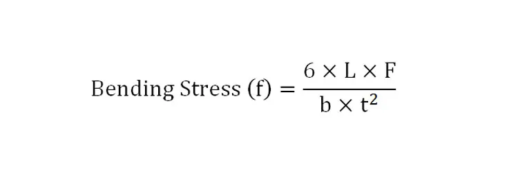
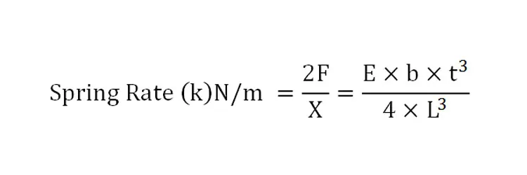
Where:
- L = Half the overall length of the longest leaf spring (m)
- F = Force applied at each mounting point to the chassis (usually half the load applied at the axle point) (m)
- b = Leaf spring width at the centre point (m)
- t = Vertical depth of the leaf spring at the centre point where it mounts to the axle (m)
- E = Youngs modulus for the material (Pa) (see table below)
- X = Spring displacement vertically (m)
The equations for a laminated leaf spring vary slightly and are:
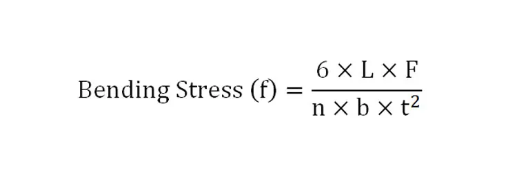
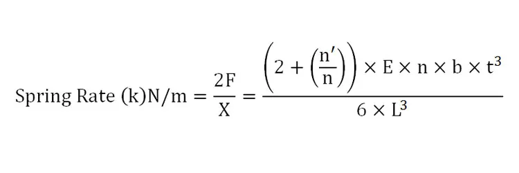
Where:
- L = Half the overall length of the longest leaf spring (m)
- F = Force applied at each mounting point to the chassis (usually half the load applied at the axle point) (m)
- b = Leaf spring width at the centre point (m)
- n = number of leaves stacked
- n’ = number of leaves directly at the spring ends
- t = Vertical depth of the leaf spring at the centre point where it mounts to the axle (m)
- E = Youngs modulus for the material (Pa) (see table below)
- X = Spring displacement vertically (m)
- Parameters for Three-point bending fixture model
Specifications
Length(L) 160 mm
Width(b) 15mm
Thickness(t) 2 mm
Support diameter 3 mm
Intender diameter 3 mm
Young’s Modulus(E) 2.1 x 10⁵ MPa
Comparison of Analytical and Numerical values for Three-Point
bending fixture
Load Analytical Numerical % Error
N ρ MPa δ Mm σ MPa δ mm ρ % δ%
100 100 0.0634 102.33 0.0569 2.33 10.25
200 200 0.1269 204.66 0.1139 2.33 10.24
300 300 0.1905 304.66 0.1709 2.33 10.28
400 400 0.2539 409.32 0.2279 2.33 10.24
500 500 0.3174 511.65 0.2849 2.33 10.24
6. CONCLUSIONS
1. The user generated mesh was found to be optimum as per requirements.
2. As per analysis results, the deformation of the body is in acceptable range as per safety norms.
3. As per analysis results, the maximum stress of the body is in the vertical direction along the base leaf and the
value suggests the design is safe.4. but comparing the two model we found that second model is in good quality and shape . the reason behind this first model taking all stess onto its first leaf and pressurized the the centre part of the model to bend or failed .
Hence, from the design, meshing and analysis, it can be concluded that the leaf spring as designed is meshed
optimally and analyzed in the best possible way to simulate real world loads/forces. All these indicate that
the body is safe to use in heavy commercial vehicle.