Assignment 8-Roof Crash Simulation Challenge
Aim :
To run the roof crash simulation on the neon car model and plot the graphs for the neon car model in post-processing.
Roof Crush - BIW
Import
• Car
• Impactor
Transforms
• This will require (in order)
• A 180° rotation about the global z-axis with the point opposite to C as base point
• A 5° rotation about the axis through axis AB
• A 25° rotation about the axis through axis AC
• A translation to put point A at global ( -3500.00, 584.822, 1343.06)
Reference image ( Full Vehicle Model )
Interfaces
• Create a Type 7 contact interface between the impactor and the car
• choose an appropriate stiffness definition
• choose an appropriate minimum gap
• change the coefficient of friction to 0.2
• choose the appropriate friction penalty formulation
• Save the data from the interface to the time history file.
Boundary condition
keep the suspension shock tower nodes locked in Z.
Impactor Boundary Conditions
• The impactor assembly contains a spring attached for stability. Create a BCS
collector to fix the free end of the spring.
• Create a moving SKEW to define the direction normal to the impactor’s
face.
• Create a BCS collector to guide the master node of the impactor rigid body
so that it is free to translate normal to the face of the impactor, but is fixed
in all other DOFs.
Imposed Displacement
• Impose the velocity of the impactor starting from 0 mm/s at t = 0. The
displacement of the impactor should be 200 mm @ 200 ms.
• Avoid abrupt changes in the acceleration of the impactor.
Control Cards
• /ANALY card
• /DEF_SHELL card,
• /DEF_SOLID card, and
• /IOFLAG card
• /SPMD card
• /TITLE card
Engine File
• Use a constant nodal time step
• Print time history every 0.0001 seconds
• Solve for 200 ms
• Create an animation file every 0.005 seconds
Include selected output in animation files:
• Elemental Energy
• Elemental equivalent plastic strain
• Elemental hourglass energy
• Elemental von Mises stress
• Nodal added mass
• Turn on parallel arithmetic
Solution and Results Post Processing
• Run the model
• Plot force vs. displacement. Check that the FMVSS 216 target load of
47,000 N (= 3 * GVW) has been met.
Roof crash example :
The above image shows the roof crash image of volvo
Procedure -
Check unit system and either follow [Mg mm s] or [Kg mm ms].
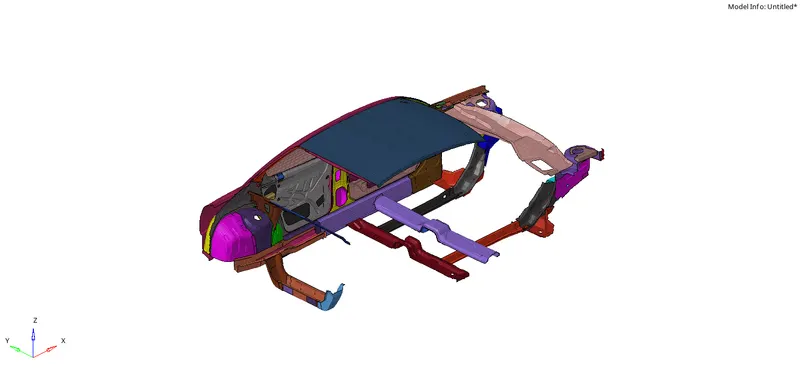
While opening hyper mesh software, A user profile window will pop up, Switch to the radioss user profile and start importing the model into the solver deck.Now after switching the user profile to radioss, Import the model (starter file) into the radioss solver deck.To import the model, Go to Standard Panel >> Import >> Import Solver Deck Import Solver Deck option should be selected to import the radioss starter file.Import the model.
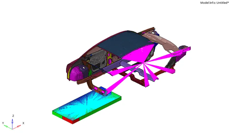
Next import the impactor.
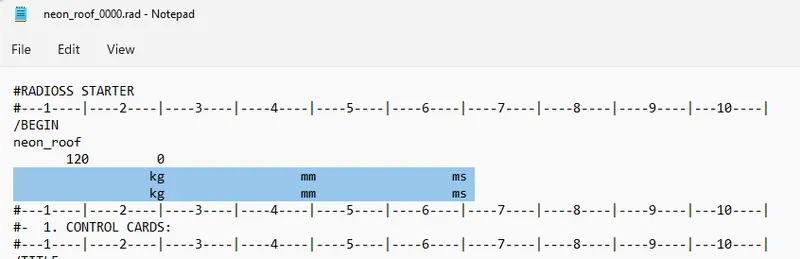
Check for units :
Open the rad file in notepad and check the units or go with other unit checking methodes
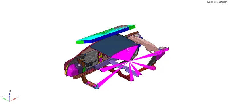
Phase 2-Transform the Impactor:
1. A 180° rotation about the global z-axis with the point opposite to C as the base point.
2. A 5° rotation about the axis through axis AB.
3. A 25° rotation about the axis through axis AC.
4. A translation to put point A at global ( 3500.00, 584.822, 1343.06).
Create the Interfaces:
Car and Impactor -
Here for this model, TYPE 7 Contact Interface is created with the recommended parameters. To create interface, Right Click on Solver Browser >> Create >> Inter >> TYPE 7.
First, we have to create Contact Interface for the Car and Impactor.
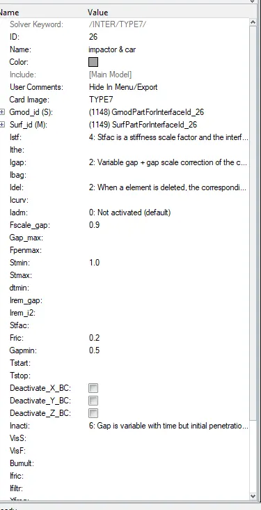
Select the slave and master nodes by switching to the components and select all the car components for slave for master nodes select all the components of Impactor.
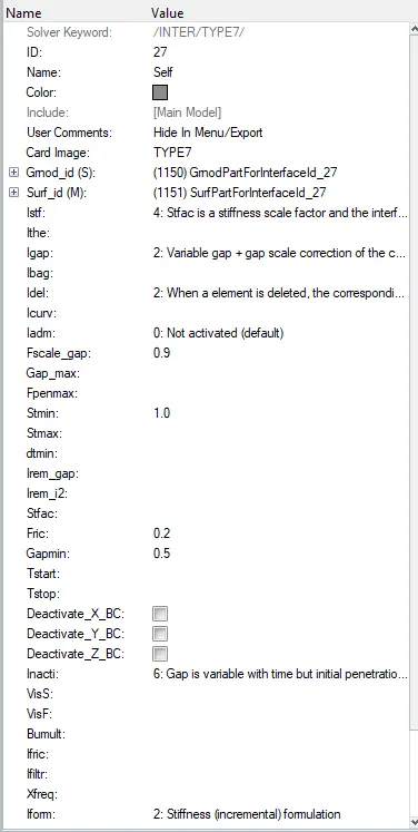
Self Impact -
The Type 7 Contact Interface for the Self Impact is created.
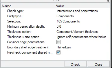
Check for the Penetration
Here check for the penetrations, to check, Go to Menu Bar >> Tools >> Penetration Check.
Create Boundary Conditions for the Suspension Shock Tower:
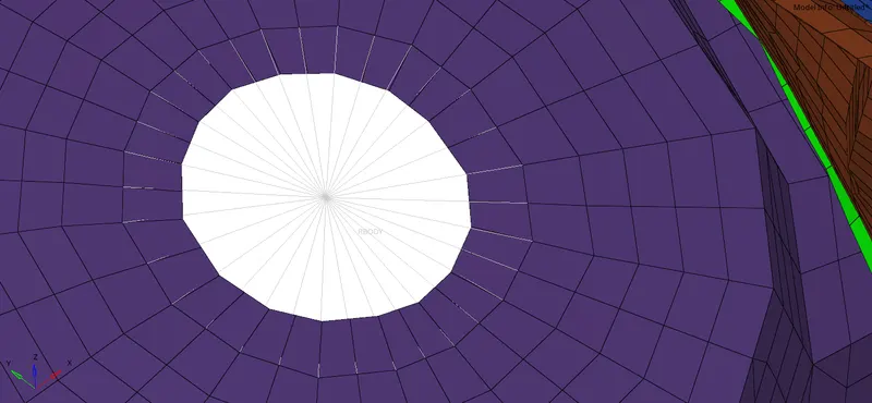
Here we have to create boundary conditions for the suspension shock tower.To create boundary conditions, Right Click on Solver Browser >> Create >> Boundary Conditions >> BCS
We need to deploy a cluster rigid connection on the suspension tower.
Create a BCS [Boundary Conditions] to Fix the Free End of the Spring:
Here we have to create the boundary condition to fix the free end of the spring. And rename it spring.To create boundary conditions, Right Click on Solver Browser >> Create >> Boundary Conditions >> BCS.Now select the free end of the spring.
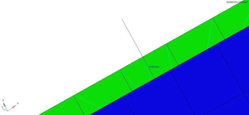
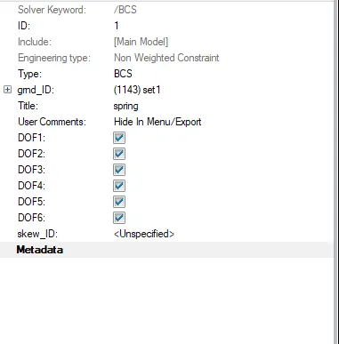
Now Constrain all the degrees of freedom for the free end of the spring.
Create a Moving SKEW to Define the Direction Normal to the Impactor’s Face:
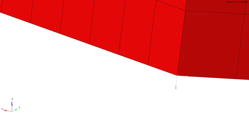
Next, we have to create the boundary condition for the master node of the impactor.For that first, we want the impactor to move only in the perpendicular direction to the impactor.To give the boundary condition to the master node. we need to create a skew.To create a skew, Right Click on Solver Browser >> Create >> SKEW >> Mov.
Create a BCS to Guide the Master Node of the Impactor Rigid Body:
Now we have to give the boundary condition to the master node of the impactor.To give, we have to create a boundary condition and rename it as Impactor_Rigid_Master_Node.To create BCS, Right Click on Solver Browser >> Create >> Boundary Conditions >> BCS,
Give the Imposed Displacement to the Impactor:
Here we have to give the imposed displacement to the impactor.To give the imposed displacement to the impactor. We have to create the boundary condition.To create the boundary condition, Right-click on the Solver Browser >> Boundary Condition >> IMDISP.After creating the imposed displacement, we have to select the impactor master node.To select the impactor node, Below the Parameter Window >> Right Click on gmd_ID >> Create Edit >> Entity ID >> Select the Node >> Proceed.We have to create the curve to assign.So, we want to impose the velocity of the impactor starting from 0 mm/s at t = 0 and the displacement of the impactor shouldbe 200 mm at 200 ms.So, we have to create a curve. to create the curve, go to the Model Browser >> Create >> Curve.
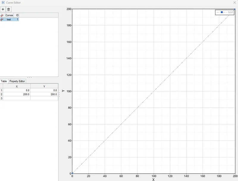
Now Select the skew to move the impactor according to the skew.Switch to the Z-Axis Direction to move the impactor in Z-Axis Direction
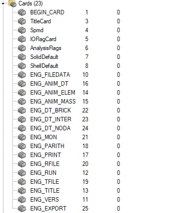
Create Missing Control Cards:
To create control cards, go to Analysis Panel >> Control Cards. and give the values

Checks:
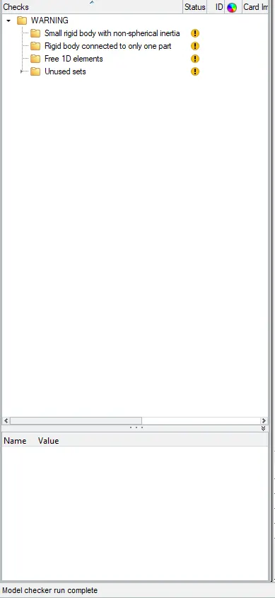
Finally, after doing all the load case setup, we have to check for the errors, whether every load case setup is fine or not.To check, Go to Tools >> Model Checker >> Radioss Blok
Run the Simulation:

The error is under the limit so it can be conciderd
Post Processing(Results):
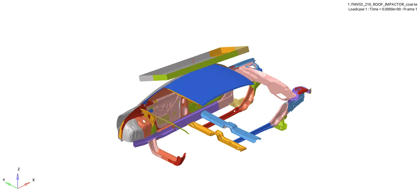
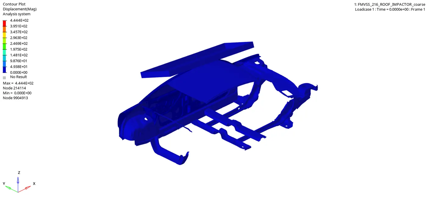
Review the Simulation using HyperView.
Displacement:
Von Misess:
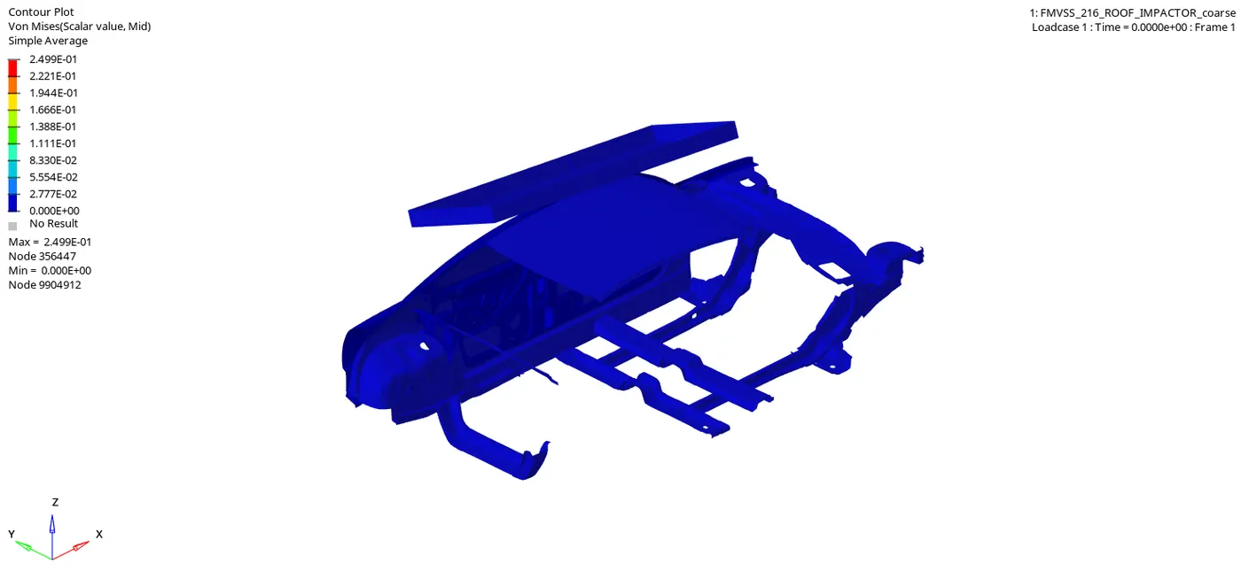
2) Plot the graphs using -Hypergraph 2D:
To plot the graph,
Interface [TYPE 7] Self Contact:
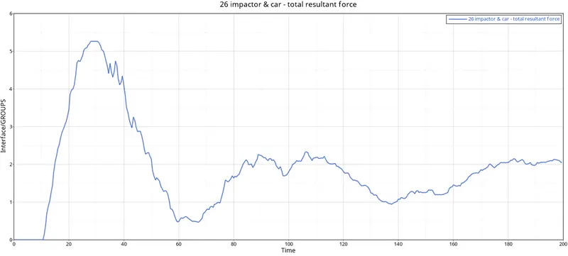
Here the interface curve starts from the origin and reaches a peak due to collision.
FMVSS 216 Impactor Spring:
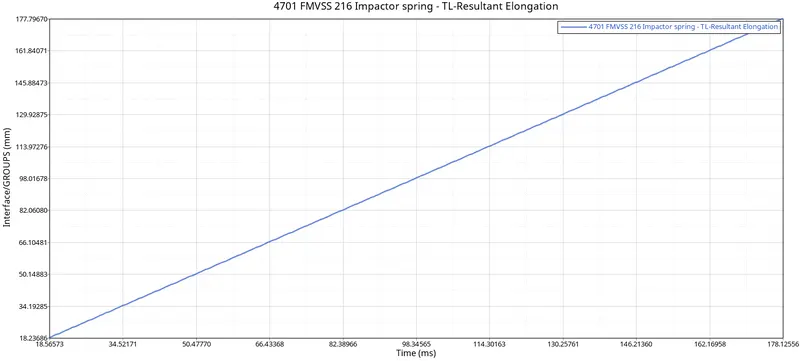
The graph was obtained for the impactor spring.
Internal Energy & Kinetic energy:
The graph was obtained for Internal energy and kinetic energy.
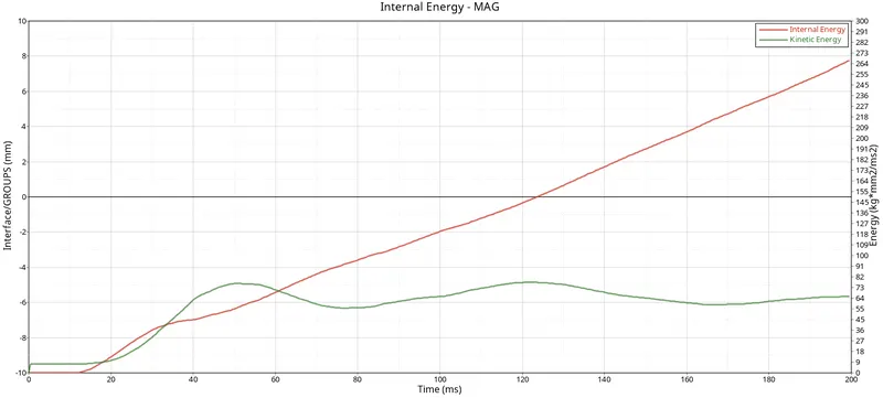
Here in the above graph, we can see that In the starting the impactor will be moving, so it will be having some velocity.So due to some velocity, there will be kinetic energy. When the impactor hits the car model the energy will transfer to the model and the kinetic energy of the model gets increases. So the kinetic energy goes on increasing.The formula for Internal Energy is I.E = Q W.Here the heat is neglected because there is no heat transfer, We will be having only work done.W=FxD,F=ma.Here the internal energy is in Zero because there is no deformation initially, So the internal energy is in Zero and starts from Zero and goes on increasing.The internal energy increases because the deformation is happening, there is a displacement, So the internal energy increases, when the displacement or deformation occurs.
Contact Energy:
The graph obtained for Contact Energy.
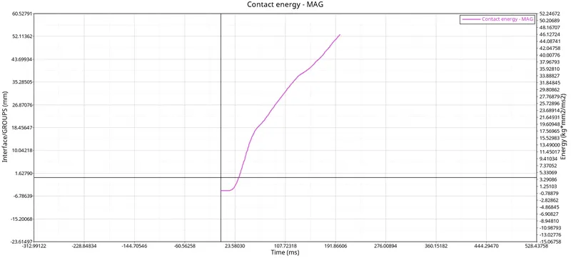
Here the contact energy starts from the origin, Cause the Car is in its initial condition.Initially, there is no contact between the Car and the Impactor.There is also no deformation initially, but when the Impactor goes and hits on the Car Roof, the contact energy starts increasing.When the deformation or displacement happens to the car, the contact energy increases, causing the car component comes into the contact with the impactor. So, the contact energy goes on increasing.
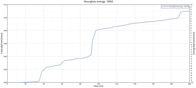
Hourglass Energy:
The graph obtained for Hourglass Energy.
Force vs Displacement:
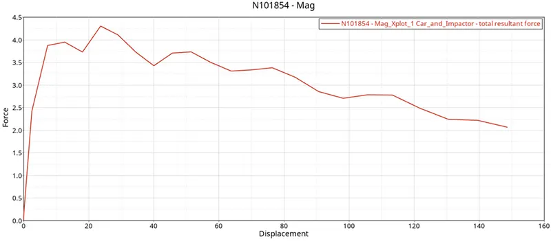
We have to plot the Force vs Displacement, to the plot, first, we have to plot the displacement graph.
To plot the displacement graph, Go to HyperView >> Build Plot.Next in the drop-down list box, Choose the Result type as Displacement, and then select the Magnitude.
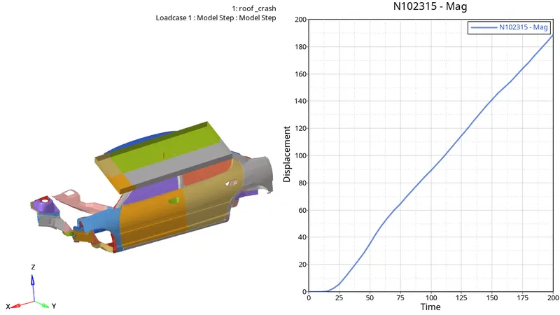
To rename X-Axis and Y-Axis to the Force and Displacement, Double Click on the X-Axis and Y-Axis, then rename it as Force and Displacement.
The graph obtained for the Force vs Displacement
Check the FMVSS 216 target load of 47,000 N (= 3 * GVW) has been met:
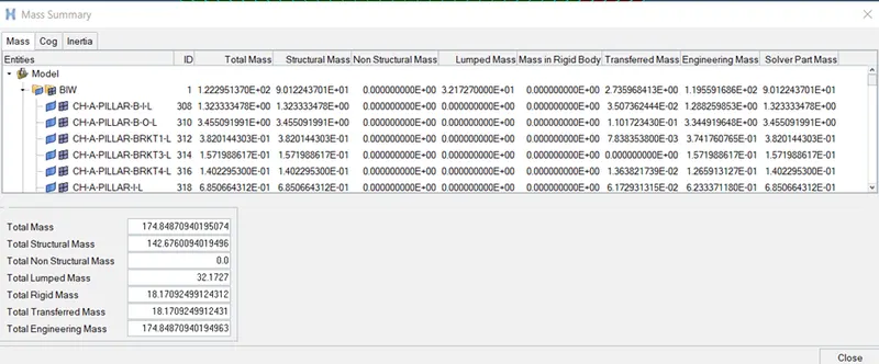
To calculate the target load of the FMVSS 216, We should check the initial mass of the car, it is around 174.8487 kg.To convert it into the weight, we should consider the gravitational force.
Load=3xGVW.
Load=3x9.981x174.848.
Load=3x1715.2657.
Load=1,715.2657N.
The target load given is 47000 N but the load attained here is 10% (1715.2657) of the target load.This is due to, cause the car model given to us is not a complete car, it’s a BIW body, so the target load we attained here is 1715.2567 N.For the whole car, the mass will be 1600 kg, if we check with this, we will be getting the target load as =3x9.91x1600=47088 N.If we run the simulation with the complete car, we will be getting the exact target load and it will meet the target load. but here the target load is not met.
Result:
As a result, the Impactor has been placed along the indicated axis. Thus, the self-impact, automobile, and impactor interfaces were each given a separate interface. Thus, the two Z-Axis nodes for the suspension tower were produced and locked by the boundary condition. As a result, the Boundary Condition was developed to fix the spring's free end. In order to designate the direction normal to the impactor's face, the SKEW was developed. As a result, the Boundary Condition was developed to direct the rigid body's master node of the impactor. The Impactor is thus given the Imposed Displacement. As a result, all of the required control cards were made. In order to produce outputs, the TH for all inputs was therefore developed. As a result, the simulation ran without encountering any issues.