Assignment 8-Roof Crash Simulation Challenge
AIM : To preform the crash on the roof of the car with an impactor and analysis where stresses are working on it.
OBJECTIVE :
Roof Crush - BIW
Import
• Car
• Impactor
Transforms
• This will require (in order)
• A 180° rotation about the global z-axis with the point opposite to C as base point
• A 5° rotation about the axis through axis AB
• A 25° rotation about the axis through axis AC
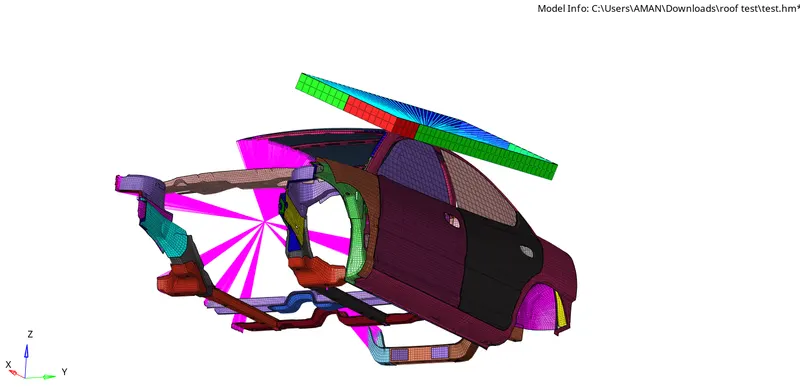
• A translation to put point A at global ( -3500.00, 584.822, 1343.06)
Interfaces
• Create a Type 7 contact interface between the impactor and the car
• choose an appropriate stiffness definition
• choose an appropriate minimum gap
• change the coefficient of friction to 0.2
• choose the appropriate friction penalty formulation
• Save the data from the interface to the time history file.
Boundary condition
keep the suspension shock tower nodes locked in Z.
Impactor Boundary Conditions
• The impactor assembly contains a spring attached for stability. Create a BCS
collector to fix the free end of the spring.
• Create a moving SKEW to define the direction normal to the impactor’s
face.
• Create a BCS collector to guide the master node of the impactor rigid body
so that it is free to translate normal to the face of the impactor, but is fixed
in all other DOFs.
Imposed Displacement
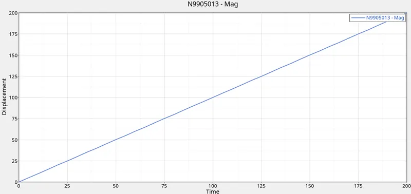
• Impose the velocity of the impactor starting from 0 mm/s at t = 0. The
displacement of the impactor should be 200 mm @ 200 ms.
• Avoid abrupt changes in the acceleration of the impactor.
Control Cards
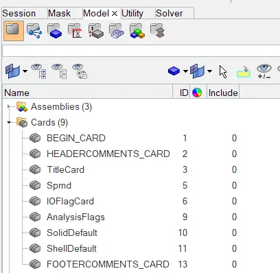
• /ANALY card
• /DEF_SHELL card,
• /DEF_SOLID card, and
• /IOFLAG card
• /SPMD card
• /TITLE card
Engine File
• Use a constant nodal time step
• Print time history every 0.0001 seconds
• Solve for 200 ms
• Create an animation file every 0.005 seconds
Include selected output in animation files:
• Elemental Energy
• Elemental equivalent plastic strain
• Elemental hourglass energy
• Elemental von Mises stress
• Nodal added mass
• Turn on parallel arithmetic
Solution and Results Post Processing
• Run the model
• Plot force vs. displacement. Check that the FMVSS 216 target load of
47,000 N (= 3 * GVW) has been met.
• Plot the energy vs. time curves
ABSTRACT : In this project we are about to see the impact of the roof of the car when it hits by an impactor.
BASIC COMMANDS:
STEP 1: Open the starter file runname_000.rad file. *Menu bar-file>import>solver desk>select .rad file>import
STEP 2: Checking unit system of the model
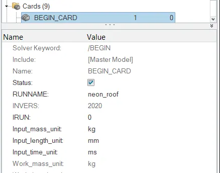
PROCEDURE OF OBJECTIVE 1: Transforming the Impactor.
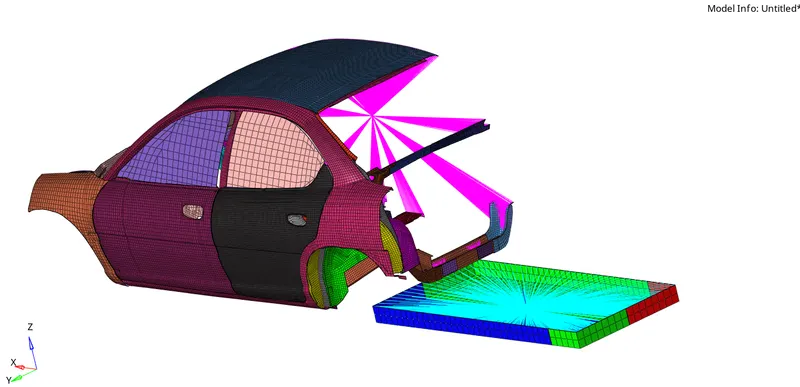
- A 180° rotation about the global z-axis with the point opposite to C as base point
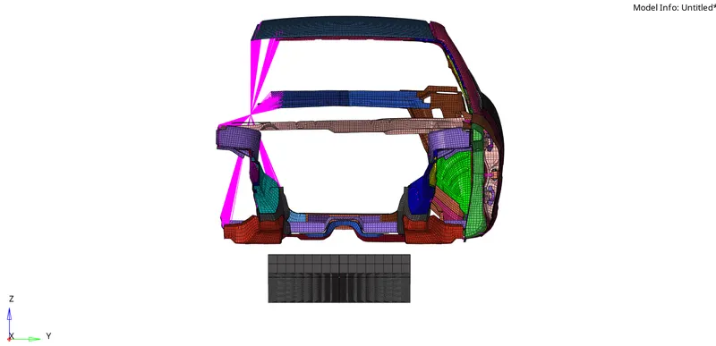
*Tool>rotate>select all elements of impactor by attachment-gives axis>angle180>rotate
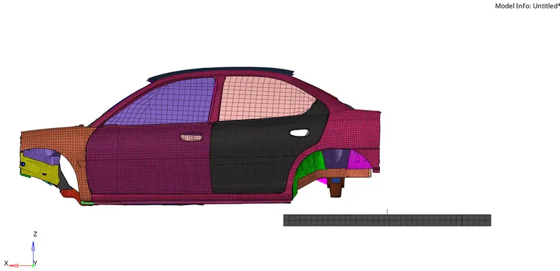
BEFORE
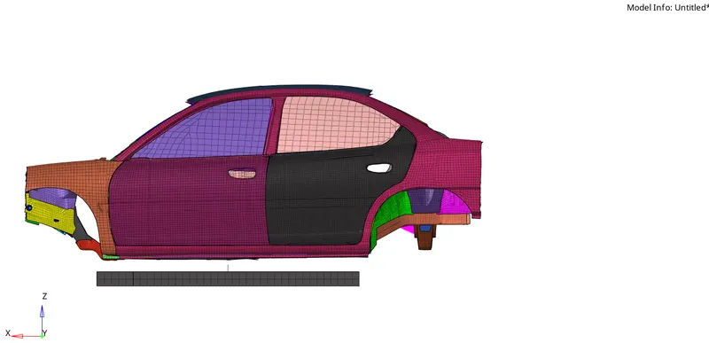
AFTER
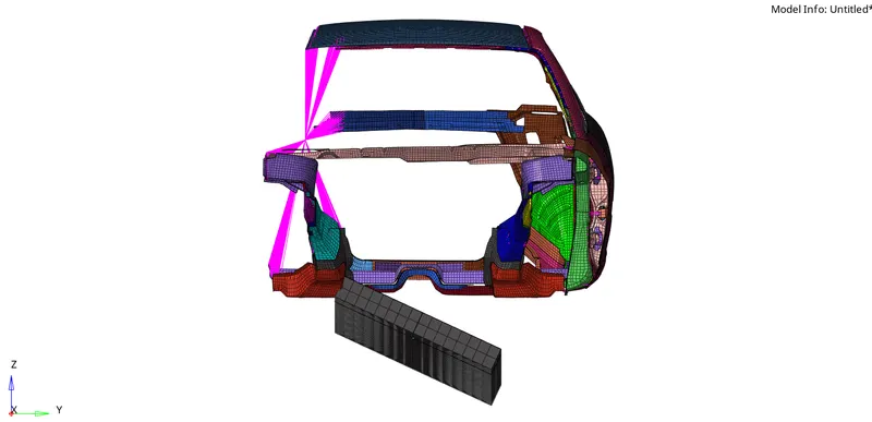
- A 25° rotation about the axis through axis AC
*Tool-rotate>select all elements of impactor by attachment-gives N1,N2 nodes toward AC>angle25>rotate
PROCEDURE OF OBJECTIVE 2: Interfaces
.Creating a Type 7 contact interface between the impactor and the car
Here we have to create two type 7 cards one for car components only and another for Impactor alone.
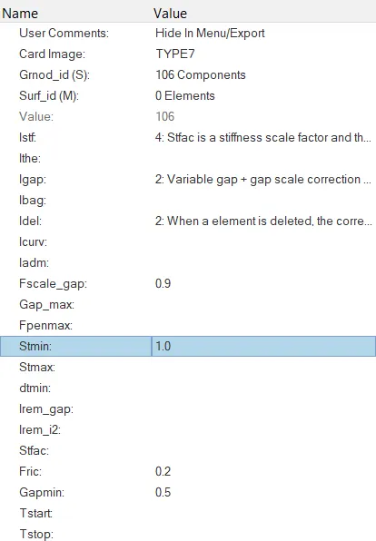
Type 7 card for Car
PROCEDURE OF OBJECTIVE 3: Assigning Boundary condition in shock absorber and keeping the suspension shock tower nodes locked in Z.
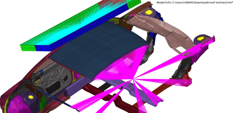
We can notice in the given model that there are no wheels and suspension arrangements so we have to create a link of 1D elements to all the three shock absorber places.
*1D>regids>calculated nodes>multiple nodes>select nodes by path>create

We have to make a moment of shock absorber only in the Z axis as below image that is why we have provided only DoF 3 and DoF 6 as seen in above image.
PROCEDURE OF OBJECTIVE 4: Assigning Impactor Boundary Conditions on Impactor.
• The impactor assembly contains a spring attached for stability, Creating Boundary Condition System Card in solver browser.
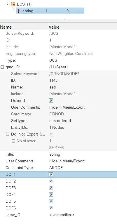
We are allowing the Impactor to only move in the normal to Imactor direction so as it is spring we have to fix the upper position of the spring
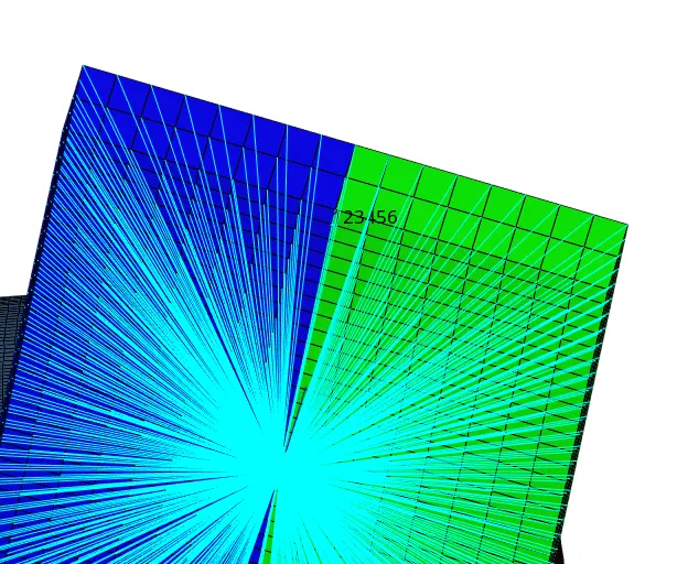
PROCEDURE OF OBJECTIVE 5: Collector to fix the free end of the spring.
- Creating a moving SKEW to define the direction normal to the impactor's face, Creating a SKEW card in the solver browser
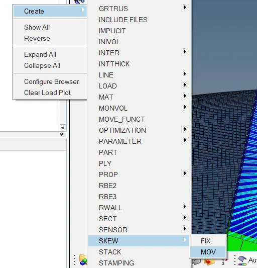
- Selecting nodes on the Impactor showing local axis .Creating a BCS collector to guide the master node of the impactor rigid body
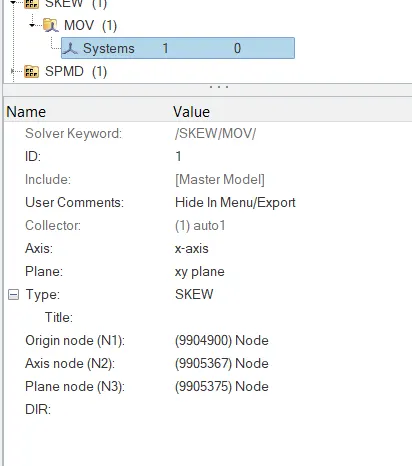
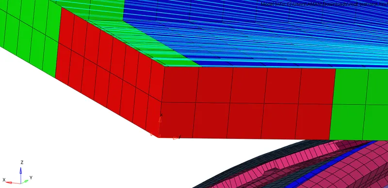
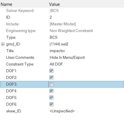
so that it is free to translate normal to the face of the impactor, but is fixed in all other DOFS.
We are allowing the Impactor to only move in the translation direction to the Z-axis we defined, that is why we are arrestion all DoF other than DoF 3 as shown in figure below.
PROCEDURE OF OBJECTIVE 6: Plotting Imposed Displacement
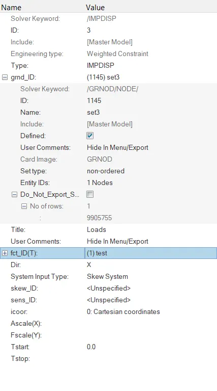
Creating IMPDISP card
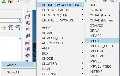
- Imposing the velocity of the impactor starting from O mm/s at t O.
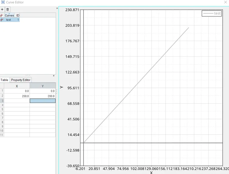
The displacement of the impactor should be 200 mm at 200 ms.
- Creating Function card in solver browser.
PROCEDURE OF OBJECTIVE 7: Creating Control Cards • /ANALY card
- /DEF_SHELL card,
- /DEF_SOLID card,
- /IOFLAG card
- /SPMD card
- /TITLE card
The engine file can be copied from any previously created engine file, just have to rename as current name of the model. Then we can Import that data file and check all required cards created
PROCEDURE OF OBJECTIVE 8: Assigning Engine File Parameters
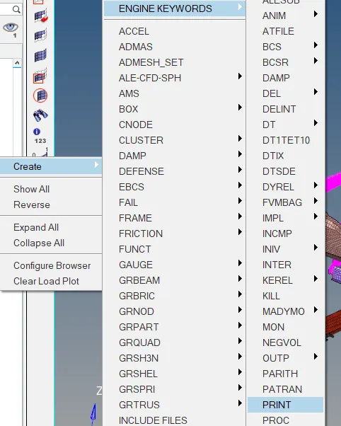
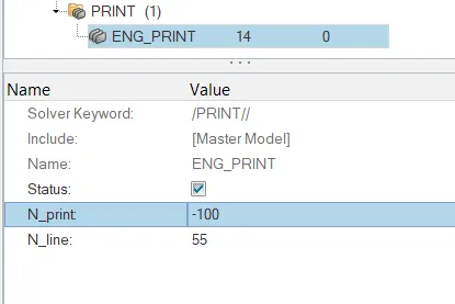
- Print time history every 0.0001 seconds
The time history is printed for 0.0001s which is 100ms.
A negative sign is given as the iteration should reduce till it reaches O.
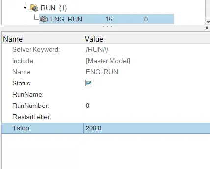
Running for 200 ms
*Model browser>cards>eng_run>Tstop=200
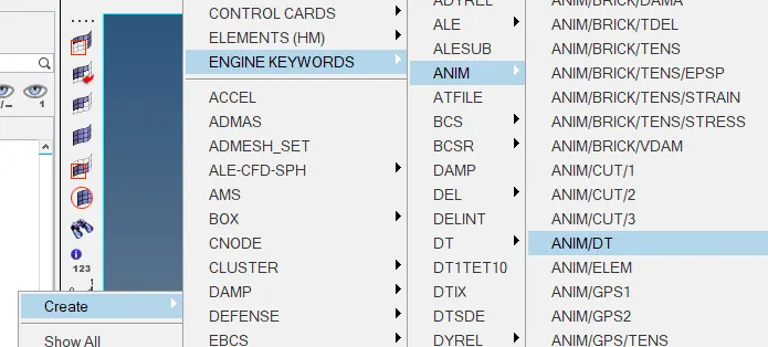
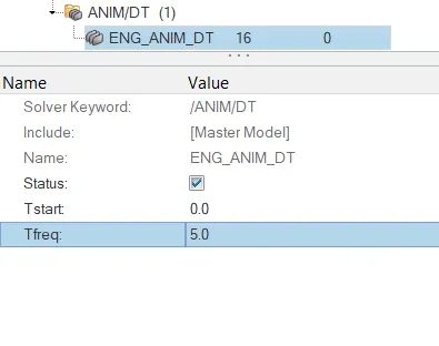
- Create an animation file every 0.005 seconds
Time-step: O.5 to 0.1 microseconds.
*Model browser>cards>eng_anim_dt>Tfreq=5.0
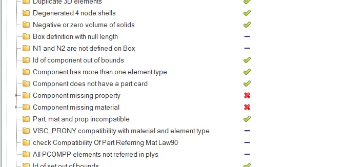
Solver the three errors.
PROCEDURE OF OBJECTIVE 9: Showing outputs in animation files.
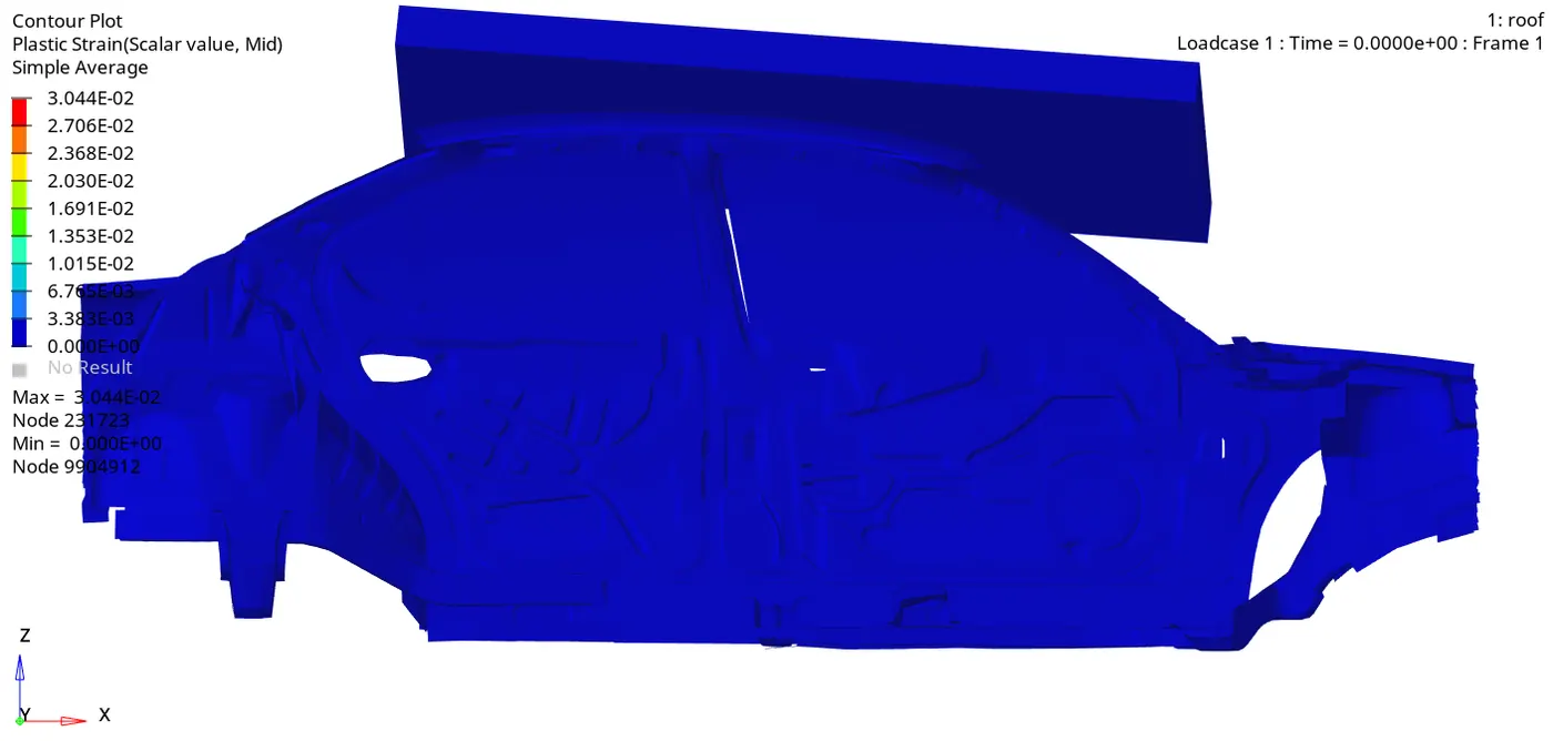
- Elemental equivalent plastic strain
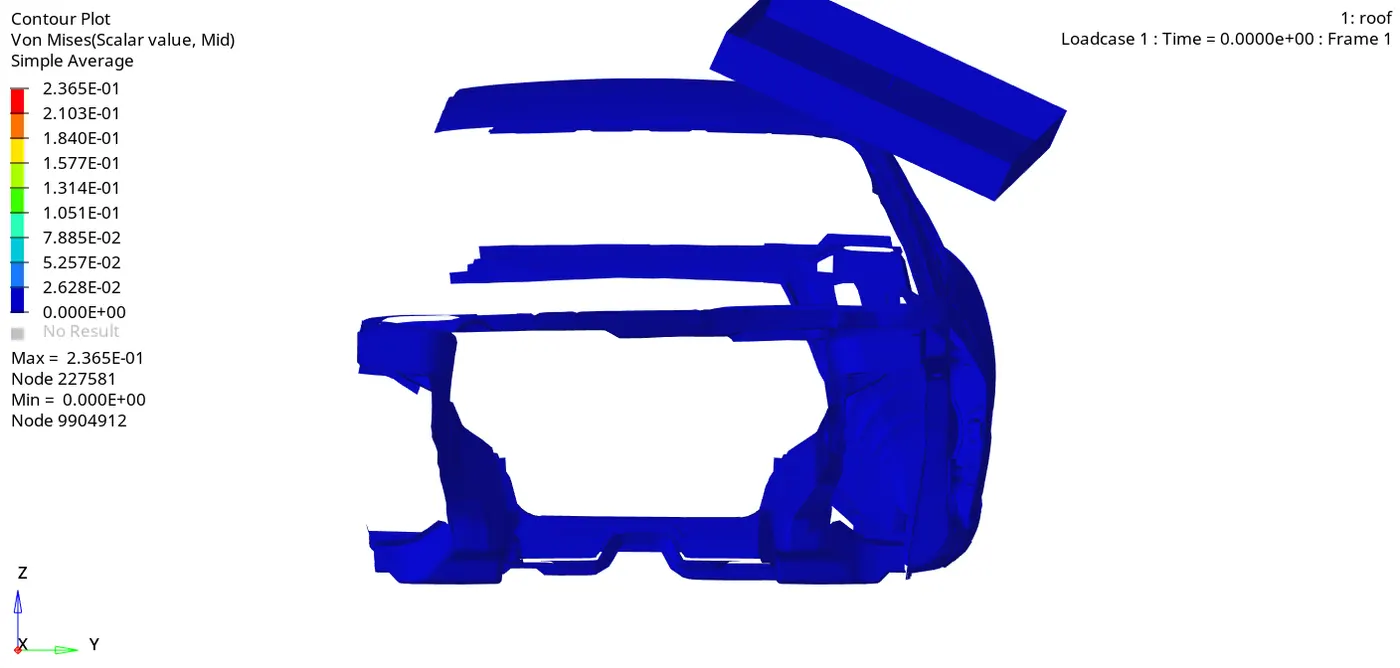
- Elemental von Mises stress
PROCEDURE OF OBJECTIVE 10: Solution and Results Post Processing
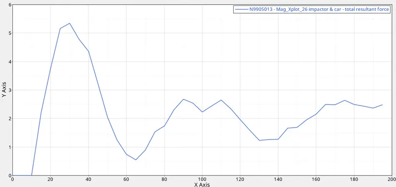
- Plot force vs. displacement. Check that the FMVSS 216 target load of 47,000 N (= 3 * GVW) has been met.
Where 3*9.81*174 = 5120.82.N
Which is no equal to 47000N
Since this model doesn't have a mass of 470OON as its only half of the body is tested for simulation and analysis.
Given model ha mass as shown
We check the mass of the vehicle as given in the model is 174.84 Kg.


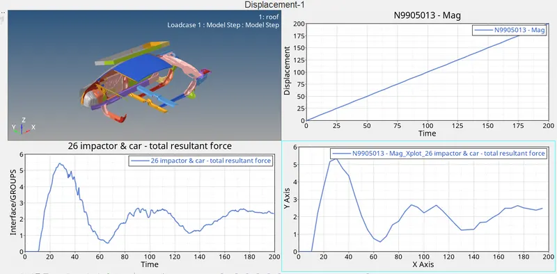
Displacement plot.
Resultant force graph plot
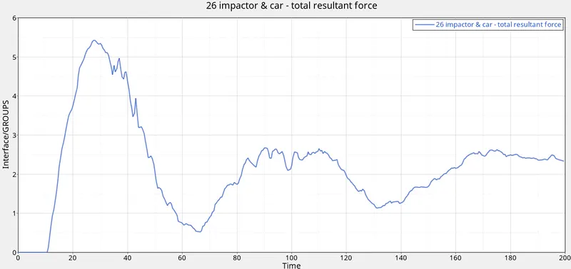
• Force Vs Displacement
OBSERVATIONS AFTER CRASH:
- We saw in the animation that the most deformation took place in the middle area of pillar and roof and the stress is then passed to the side of the rest of the components.
- We observed that the impact of the crash is mostly at the middle pillar side door of the car and by looking at this we can say that the seating area of the driver and passenger will be also impacted which can cause severe injury to them.
- The energy graph is shown of Internal energy, Kinetic energy, Contact energy, Hourglass energy and Total energy Vs Time.
- We can see that Internal energy and Total energy increases with respect to time. Hourglass energy and total energy graphs have values near to zero and almost constant as time increases.
- Kinetic energy is seen less than 100Kg mm/ms and Internal energy is seen to be increasing w.r.t time.
LEARNINGS :
İmporting starter file runname_0000.rad file
Using Radioss command
Running runname.h3D file in Hyperview to see animation
Reading runname_0001.out file
Using Hypergraph 2D.
Observing energies graph.
Changing Type 7 parameters.
Force Vs Displacement graph
Various Simulation
Type 7: Type 7 card is used to simulate all types of impact between a set of nodes and master surface. Main advantage of type 7 is stiffness is not constant and increases with the penetration preventing the node from going through the shell midsurface.
Istf 4: Stfac and stiffness is computed from both master and slave characteristics.
Igap 2: variable gap + gap scale correction of the computed gap.
Idel 2: When a 4-node shell, a 3-node shell or a solid element is deleted, the corresponding segment is removed from the master side of the interface. It is also removed in case of explicit deletion using Radioss Engine keyword /DEL in the Engine file. Additionally, non connected nodes are removed from the slave side of the interface.
Stmin 1: minimum stiffness (N/M) GAPmin : Minimum gap for impact activation.
Inacti 6: Gap is variable with time but initial penetration is computed.
Iform 2: Stiffness (incremental) formulation. Hourglass Energy: Hourglass energy is the work done by the forces that take away from the physical energy of the system.
Von Mises stress : It is a value used to determine if a given material will yield or fracture. It is mostly used for ductile materials, such as metals. The von Mises yield criterion states that if the von Mises stress of a material under load is equal or greater than the yield limit of the same material under simple tension then the material will yield.
GVW (Gross Vehicle Weight): The gross weight of a vehicle (GVW) is the weight of the empty vehicle plus the weight of the maximum payload that the vehicle was designed to carry.
FMVSS (Federal Motor Vehicle Safety Standards): Federal Motor Vehicle Safety Standards (FMVSS) specify mandatory minimum safety requirements for the design, construction, performance and durability of vehicles, as well as regulated automobile safety-related components, systems and design features.
DRIVE:
https://drive.google.com/file/d/1T3Gx1TG66xLeTg5GdD5LkbnyfnPHjqgL/view?usp=drivesdk