Assignment 7-Side Pole Crash Simulation Challenge
AIM:To perform the crash on the side body of the pole and analysis where the stress are working on it.
Objective:
Neon side crash -BIW
- Check unit system and either follow [Mg mm s] or [Kg mm ms].
- Create appropriate interface ,friction 0.2 and recommended parameters.
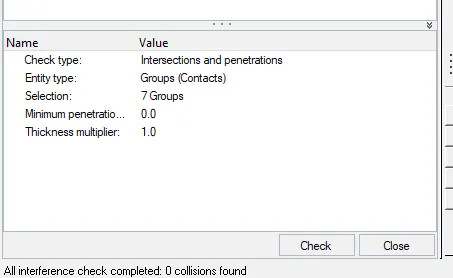
- Make sure of no penetration and intersections.
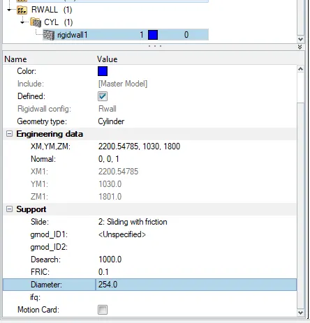
- Create rigid wall with friction 0.1 as per referance model.
- Compare the model weight with the referance model and use added masses to reach target weight 700kg while getting CG about the required range.
- Initial velocity as shown in picture.
- Use model checker to ensure good quality.
- Timestep :0.5 to 0.1 microseconds.
- Run 80ms.
Output requests:
- Sectional force in the cross member.
- Intrusion at B pillar,hinge pillar and fuel tank region.Provide recommendation on what can help to reduce Fuel tank intrusion.
- Peak velocity of inner node of the door.
ABSTRACT:In this project we are working on the side door panel and where the vechile is crash with the pole.Generally side door panel consist two side door and electric control panel attached to it.Here we see the impact on the vechile hinge pillar,fuel tank after the section 1 an section 2 after it hit the pole.
Procedure of the objective.
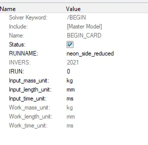
Check units system and either follow[Mg mm s] or[Kg mm ms]
- Import the given model into the GUI.
- Go to the File>Import>Solver deck and >click on Neon 0000.rad file.
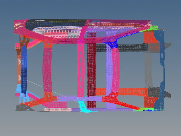
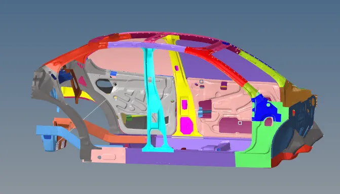
- We should have to check the units system of the given model>Go to the Model Browser> cards>Being Card>see the units system.
Procedure for Objective 2:
- Creating the Interface:
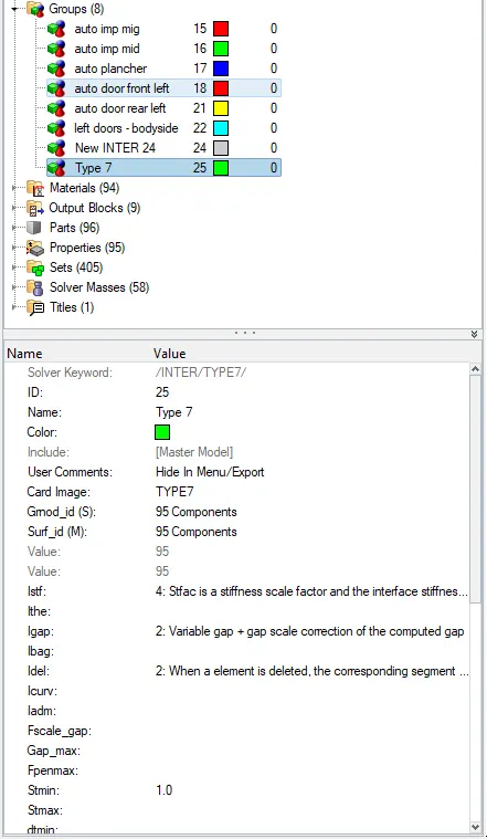
- The inerface in this model is type 7 interface and we should provide the details of the Type 7 in the entity section.
- To create a new interface we should go to Model browser>Group tab>create a new interface >give the values in the entity browser.
- In the entity editor we should go to the Name :type 7>Card image:Type 7>select the components>give the Istf(stifness value):4 stfac is a stiffness scale factor and interface stiffness.Igap value as 2 variable gap+gap sacle correction of the computed gap.Idel(Nodes and segments deletion):2 when a element is deleted the correponding segment.stmin(minimun stiffness =1.0).In active as 6 gap in the variable time but not the pentration component.
Make sure having no pentration and intersection:
- For the checking of the pentration and intersection we should have to go to the Tool>check Penetration.
- We can see the entity tab in the model and we should have to check the selection of the compounds.
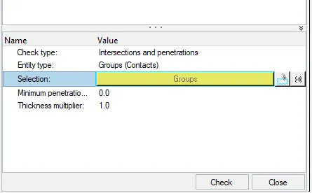
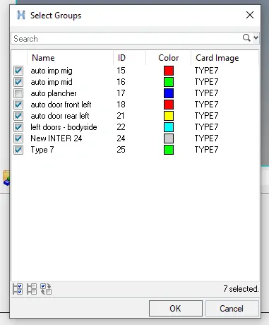
- We should click on Ok and interface and the penetration checks will be taken place and they will show the All interfaces check completed and 0 collisions found.
Procedure for Objective 4:
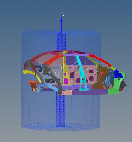
Craeting a Rigid pole with the friction of 0.1
- For the Rigid pole we should have to go to solver Browser>Create>Rigid wall>Cylinder.
- We should have to change the Geomenty Tpe :cylinder>XM,YM,ZM VALUES as:2200.54785,1030,1800>and support>slide:2 sliding with friction>Friction:0.1>Diameter=24.0.
Procedure for the objective 5:
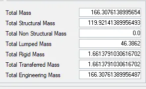
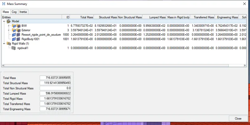
Adding masses for the model as that it can reaches 700 kg while gerring the CG as the required range.
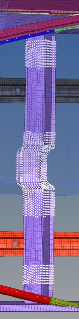
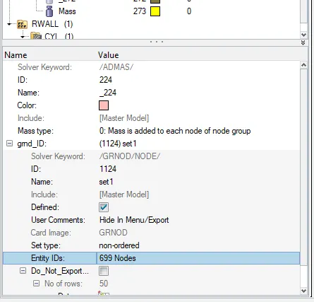
- For the adding of the mass we should go to the solver deck and create a new ABMASS.
- First we have to check the Total mass and we should have to create the ABMASS and give the nodes so that it creates the mass to thr body.
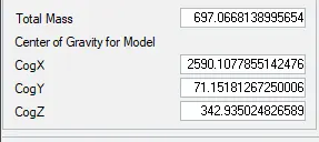
Checking the COG:
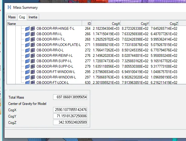
- For the centre of Gravity we should go the the Tools and check the COG of the model.
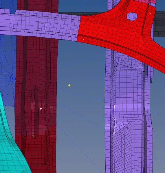
- We should have to define the COG of the model by Go to Geomentry>Nodes>x,y,z values,and click on create the nodes will be created.
Procedure for the Intial Velocity:
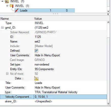
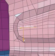
- For giving the INIVEL we should go to the solver Browser>Create >Boundary condition>INIVEL>select the nodes>velocity parameters should be given.
- we should go to the solver Browser>Create GNOD>create a new GNOD and select the node>go the INIVEL>select the nodes and the intial velocity will be displayed.
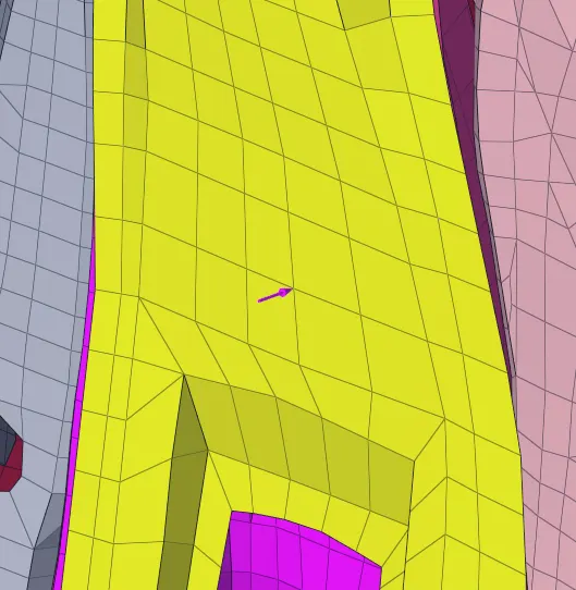
- The intial velocity will be displayed in the model.
Procedure for the objective Run for the Model Check:
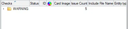
- We should have to check the errors in the model check
- Go to the Tools>Model checks>Radioos Element>Click on ok.
- If any warning were been showing go the Auto check and run it so that we can decrease some warnings.

procedure for the Time step 0.5 to 0.1 microseconds
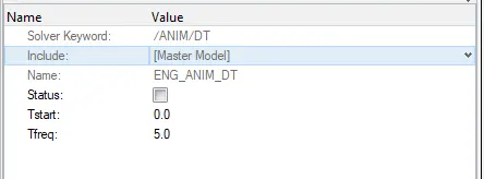
- To have the Time step of Tfreq=5
Procedure for the Run time of the Model
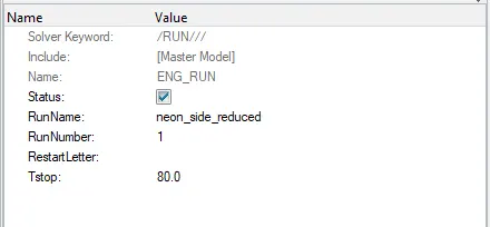
- Go the model Tstop= 80ms
Procedure for creating the Frame :
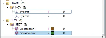
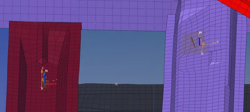
- For creating the Frame go to the solver Browser>Create >Frame>Mov>Give the nodes>click on ok.
Procedure for creating the section of the Model.
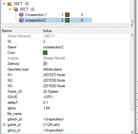
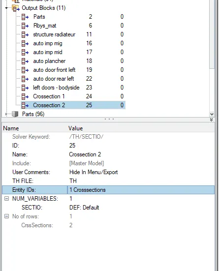
- Create a new sec in the solver browser>sec>mov>select the elements> and nodes>create a new Ishell and give the COG.
Procedure for the Intrusion for the given model.
- Create a new skew >Give the nodes>
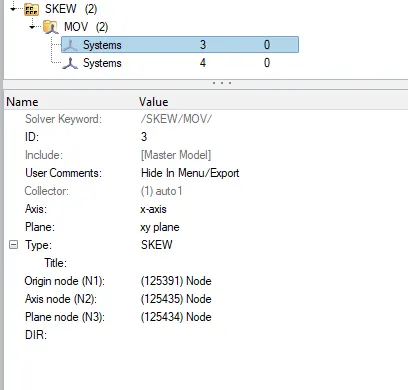
- Intrusions were created on the model.
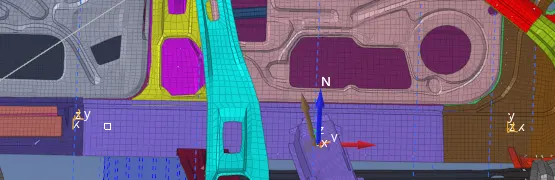
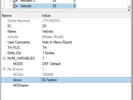
Procedure for Creating peak at the inner door panel
- We shoukd have to create the inner velocity on the door panel.
Simulation for the side Crash analysis:
- Open the Hypermesh Radioos solver.
- Import the solver desk _0000.rad file.
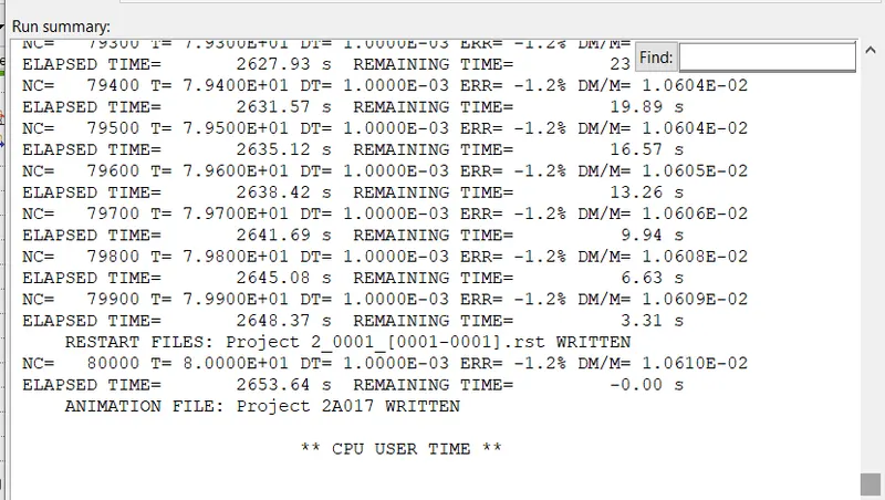
- Simulate the model as Radioos>save PROJ2_0000.rad file>-nt 4 >Radioos.
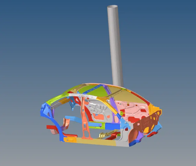
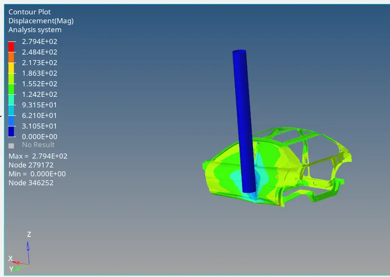
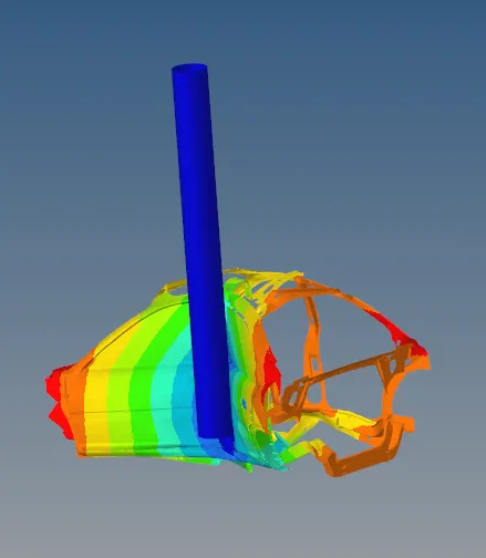
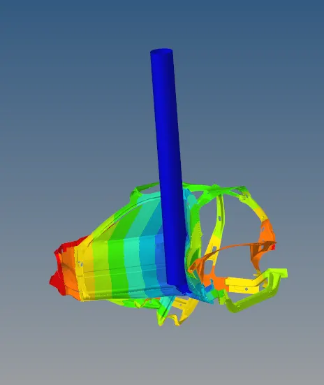
- clcik on hyper view import .h3d file.
Ploting of the Graph:
- Go to the Hyper graph>Click on import the to1 file.
- And select the global variable
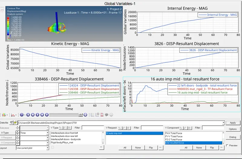
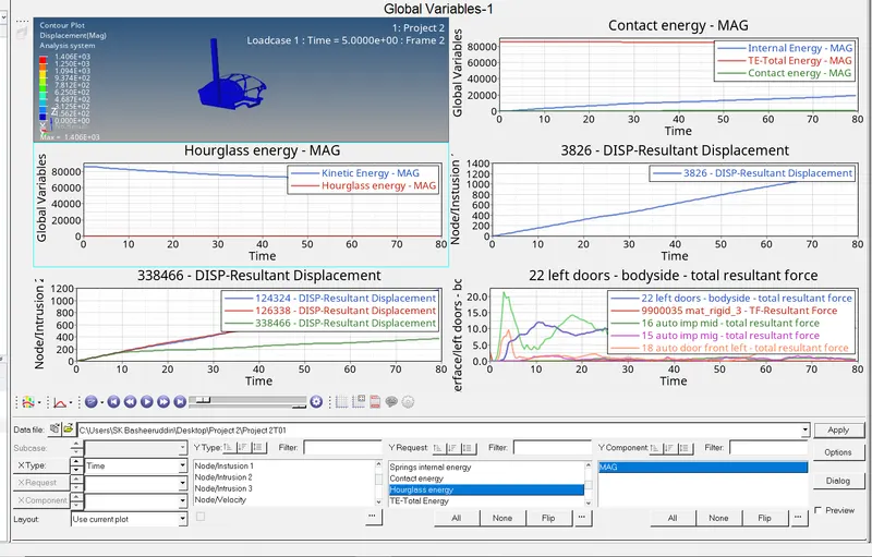
- To plot the graph, go to the Client Selector option in the Tool Bar >> Change it to HyperGraph 2D >> The HyperGraph is opened >> Select the Data File from the respective folder >> Select Cross-sections, Parts > Internal Energy, Kinetic Energy, Total Energy, Hourglass Energy, Contact Energy > MAG >> Click Apply.
- The energy graph is shown of Internal energy, Kinetic energy, Contact energy, Hourglass energy and Total energy Vs Time.
Observation:
- We saw in the animation that the most deformation took place in the middle pillar area and the stress is then passed to the side of the rest of the components.
- We observed that the impact of the crash is mostly at the middle pillar side door of the car and by looking at this we can say that the seating area of the driver and passenger will be also impacted which can cause severe injury to them.
- The energy graph is shown of Internal energy, Kinetic energy, Contact energy, Hourglass energy and Total energy Vs Time.
We can see that Internal energy increases with respect to time whereas Internal energy starts falling down from its peak as time increases. - Contact energy and hourglass energy graphs have values near to zero and Total energy remains almost constant as time increases.
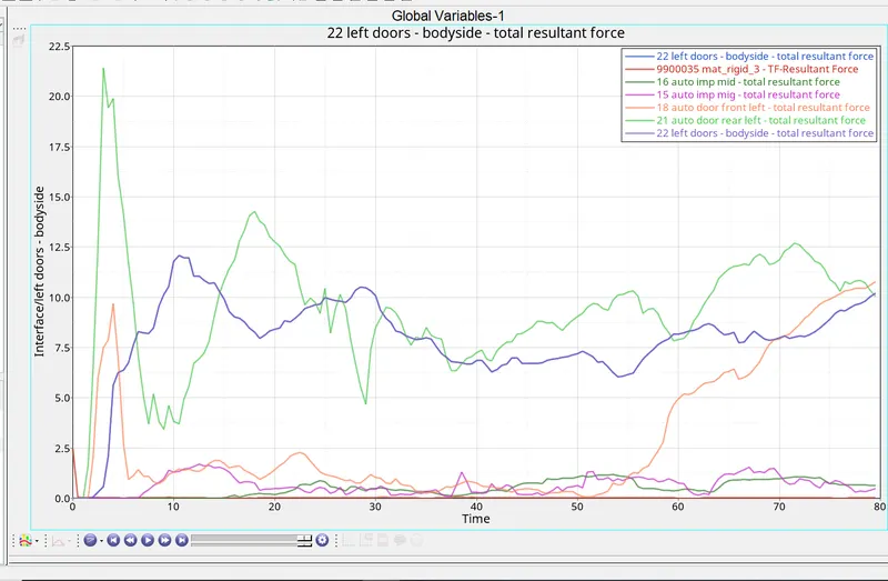
- we have seen seen that total resulant force in the model in deforming more for every 10 sec of the it was increasing as the hit the pole.
- We can see that the hinge displacement is more linear deformed as compared to the fuel tank is less deformable.
- As the peak velocity is go on increasing as it was reaches the deformation as it was linearly increasing as respect to the time it was deforming as the time increases.
Terms used:
Centre of Gravity:
The center of gravity (COG) of an object is the point at which weight is evenly dispersed and all the sides are in balance. A center of gravity can change as the mass changes but in many other cases, it's a fixed location.
Cross-Section:
A cross-section is a section made by a plane cutting anything transversely, especially at right angles to the longest axis. The Section generally means to cut the model into a part so that we can look into the component how it is from the inside. The section can be cut through the different angles which helps to look into the component from a different perspective.
Type 7:
The general purpose of the TYPE 7 interface is that it can simulate all types of impact between a set of nodes and a master surface. Automatic node to surface contact gap can be constant or variable. The main advantage of this type of interface is that the stiffness is not constant and increases with the penetration preventing the node from going through the shell mid surface.
Rigid Wall:
The Rigid wall is a virtual wall created to perform the crash analysis on the body. The Rigid wall has no certain shapes or dimensions. It can be made as flexible as possible and It can sustain the load and thus, helping out to get a crashworthiness analysis.
Penetrations:
Penetration as the name suggests, a node gets penetrates the element and causes it to fail during the simulation. The penetrations are to be removed to get a better result.
Intrusions:
An intrusion generally means to get into one’s own property or territory. In HyperMesh Intrusions are checked to see if the component is withstanding crash making sure that the component doesn’t fail miserably.
Initial Velocity:
Initial velocity is the velocity of the object before the change in acceleration.
Peak Velocity:
The Peak velocity is the highest velocity attained during the impact of an object at a particular time.
Energy Error:
If the energy is attained on the negative side then the energy is dissipating the body and therefore the error level increases from 0 to negative.
If the energy is attained on the negative side then the energy is taken to the body and therefore the error level increases from 0 to negative.