Assignment 7-Side Pole Crash Simulation Challenge
- Objective: To perform side impact analysis on the given car model.
- Procedure:
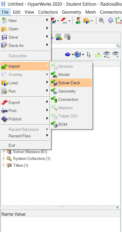
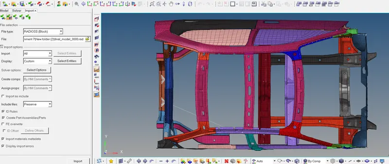
Import the given .0000 rad file. Go to File > Import > Solver Deck. Select File type as RADIOSS and in the file selector, select the required file and click on Import. The file will be imported.
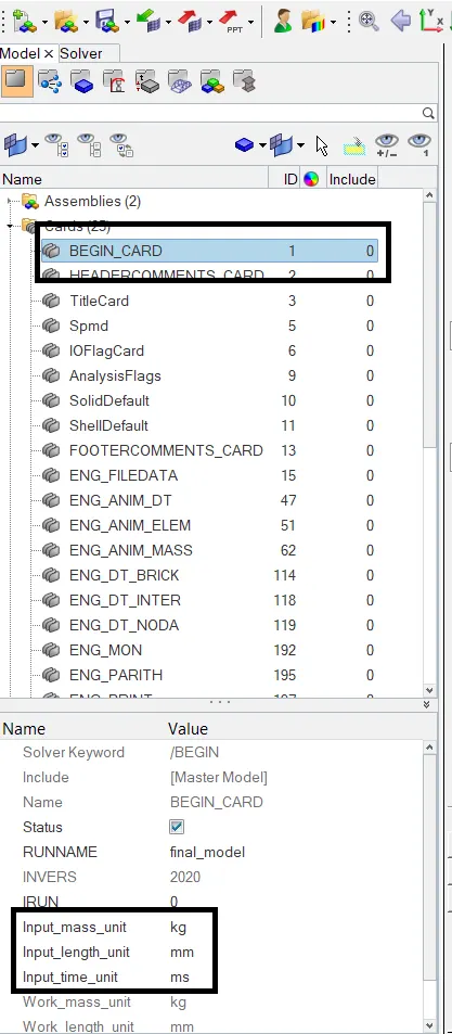
Check the unit system used so that we can proceed further. Go to Model browser > Cards > BEGIN_CARD. The unit system used is mm, Kg, ms as seen below.
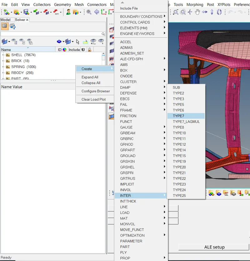
Now create Type 7 contact interface between all the componenets of the car model. Go to Solver browser > Create > INTER > TYPE 7.
Select interface parameters Istf = 4, Idel = 2, Fcale_gap = 0.8, Stmin =1, Fric = 0.2, Gapmin = 0.5, Inacti =6 and Iform = 2. Right click on the Grnod_id and click on Create. Set the Entity Id to
components and select all the components.
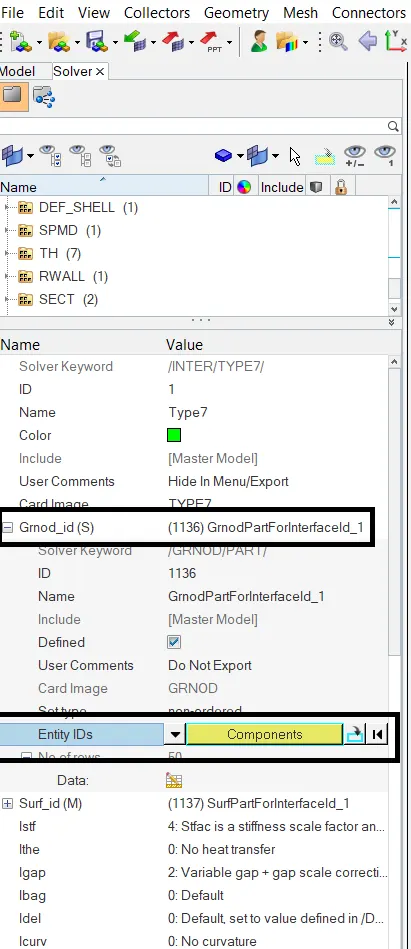
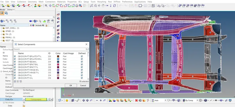
Repeat similar procedure for Surf_id selector to define the master surface. The contact interface is now created.
Now apply initial velocity to the model in global Y direction since we want to impact the side of the car to a pole. Initial velocity of 35mph is to be applied. So, following the consistent units, we will apply
velocity of 15.64 m/s. Go to Solver browser > Create > Boundary Conditions > INIVEL.
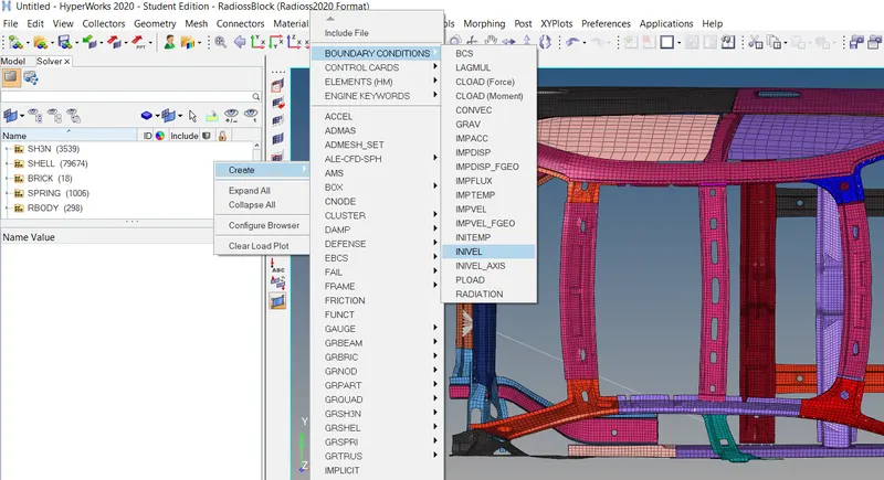
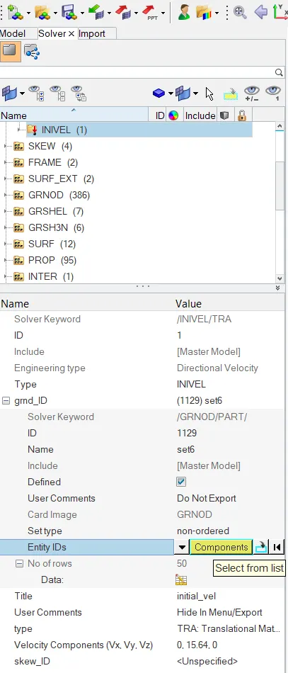
Right click on the grnd_id and click on create. Set the Entity ID's selector to Components and select all the components as shown below. Click on OK. Select the type as TRA. Enter the velocity
components Vx and Vz = 0 and Vy = 15.64. The initial velcoty is now defined.

Now define a cylindrical rigid wall on the side of the car model. Go to Solver browser > Create > Rwall > CYL.
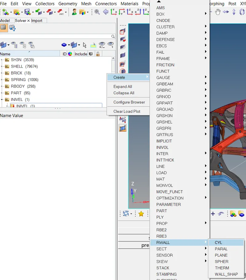
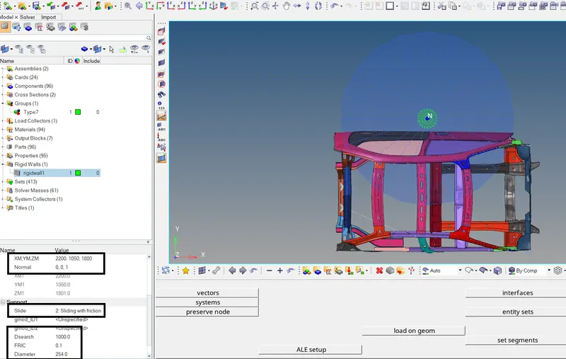
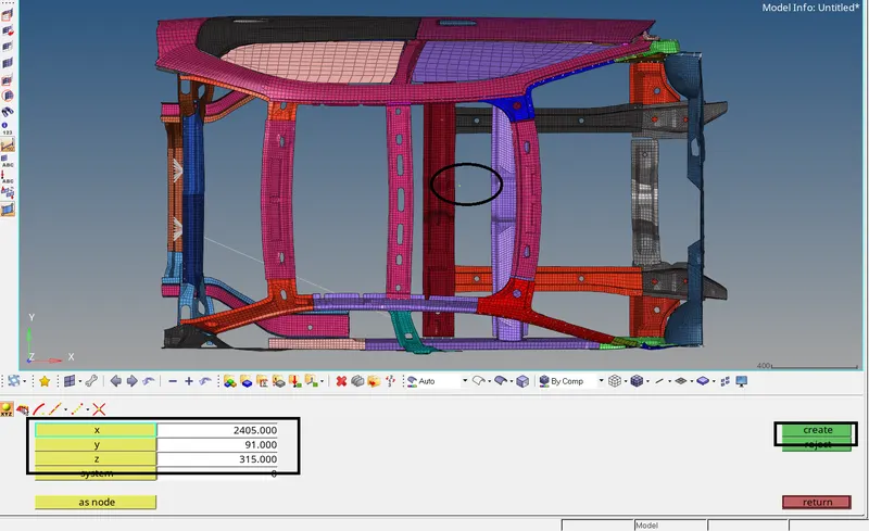
Select a node on the side of the car model which will give the coordinates for XM, YM, ZM in the XM, YM, ZM selector. Once we get the coordinates, we can change the values of YM to offset the rigid wall from
the side to define small distance between the rigid wall and the car model. In the Normal tab, enter values for X and Y = 0 and Z = 1, i.e the normal of the cylindical wall lies in Z direction as seen below.
Toggle the Slide type to 2 (sliding with friction) and enter friction value = 0.1 and search tolerance Dsearch = 1000. Enter diameter = 254 for the rigid wall diameter. Rigid wall is now created.
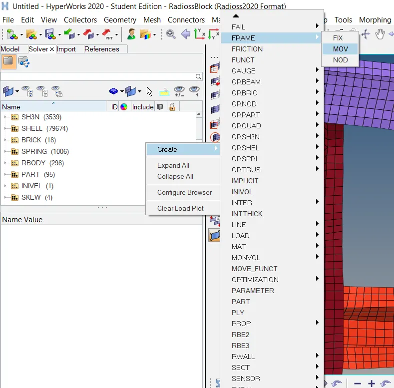
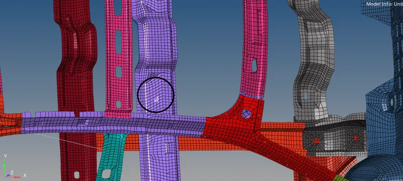
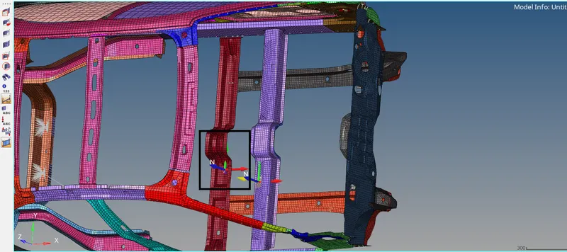
Now to create croos section for the cross memebers, first we need to create moving frame. Go to Solver browser > Create > Frame > MOV > create by node reference. Select the displayed nodes and click
on Create.
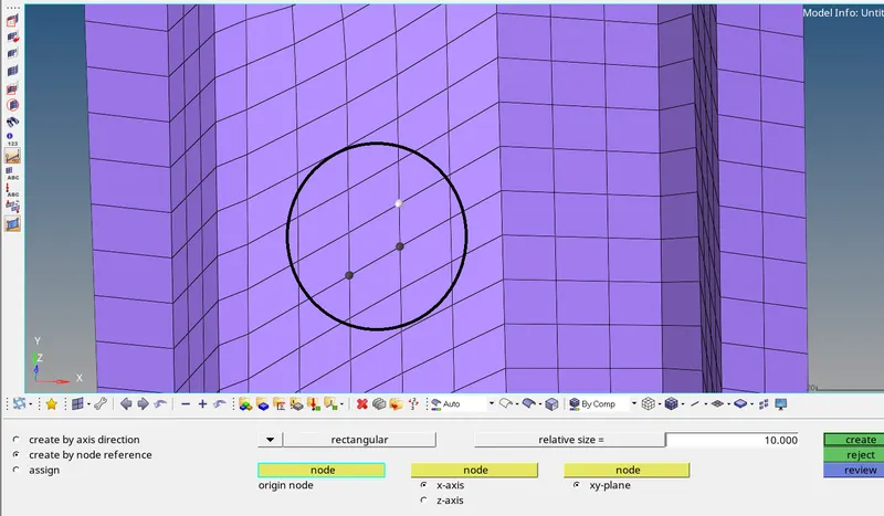
The moving frame is now created.
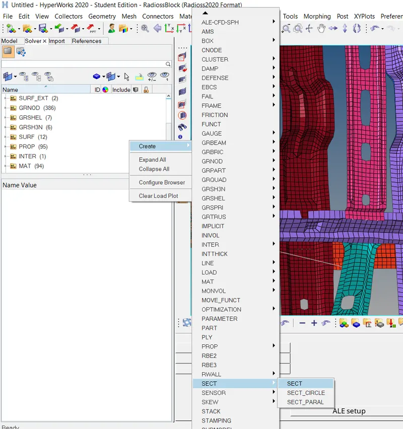
Now to create the cross section, go to Solver browser > Create > SECT > SECT.
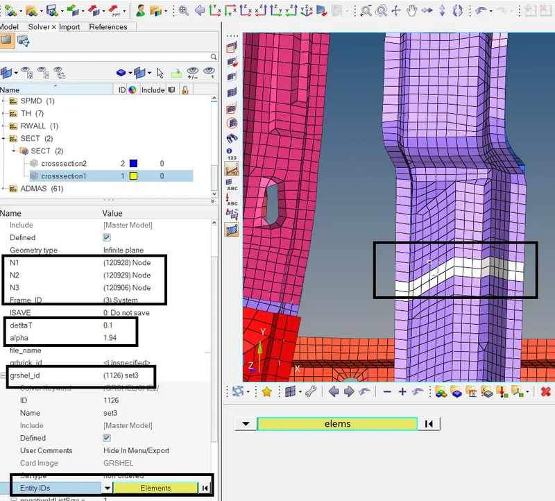
In the N1, N2, N3 selector, select the same three nodes which we selected earlier to create the moving frame. In the Frame_id, select the earlier created moving frame. enter deltaT = 0.1 and alpha = 1.94,
and Iframe = 12. Right click on the grshel_id and hit create. Set the Entity IDs selector to Elements and select the displayed two rows of elements. The cross section is now created.
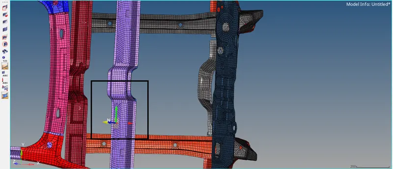
Similarly, create cross section for the other cross member.
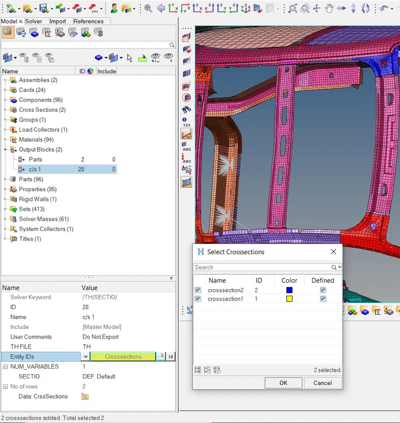
To request the output at the cross memebers, go to Modal Browser > Outpout Blocks > Create. Rename it to c/s 1. Set the Entity IDs selector to Crosssections and select the created cross section at the
cross members. The output request is now completed.
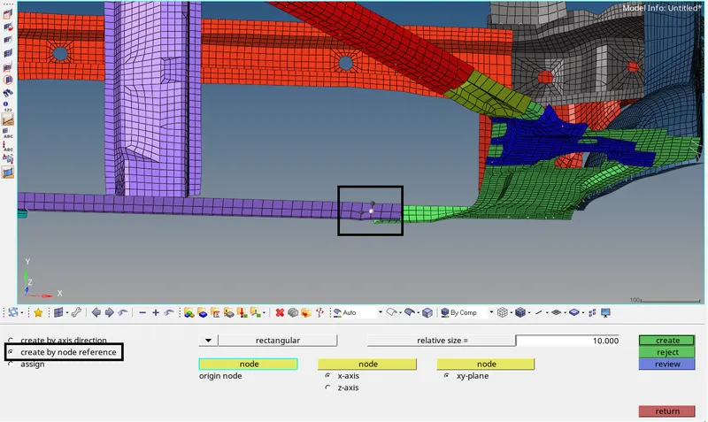
We have to find the intrusions at the B pillar, Hinge pillar and the fuel tank region. For that, we first need to create moving skew. First we will create skew for finding instrusion at the hinge pillar. Go to Solver
browser > Create > Skew > MOV > create by node reference. Select the displayed nodes on the opposite side of Hinge pillar and click on Proceed. The moving skew will be created.
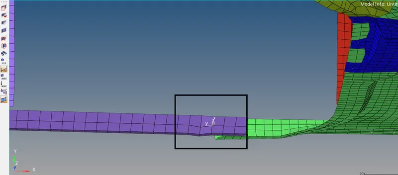
Now go to Model browser > Output Blocks > Create. Rename it to hinge pillar. In the Entity ID's selector, select the displayed node on the Hinge pillar. In the Iskew selector, select the moving skew which we
had just created on the opposite side. The output request for intrusion at the hinge pillar is now completed.
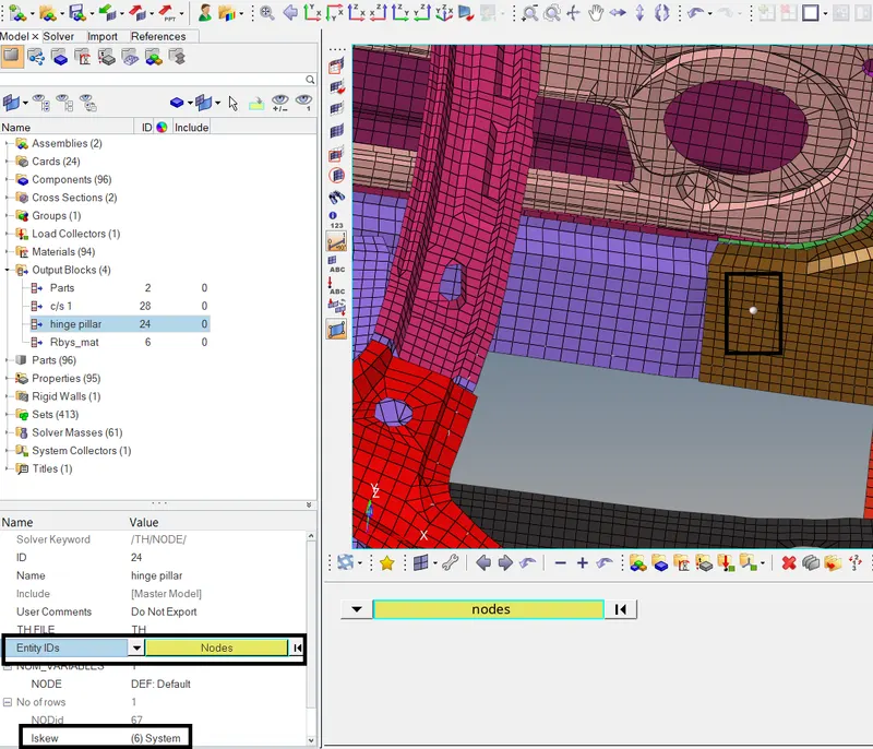
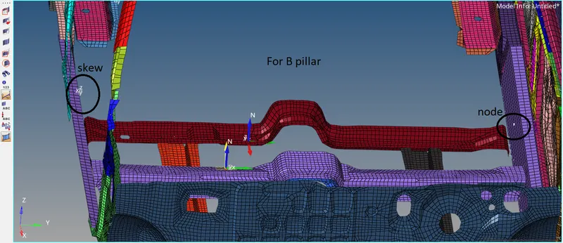
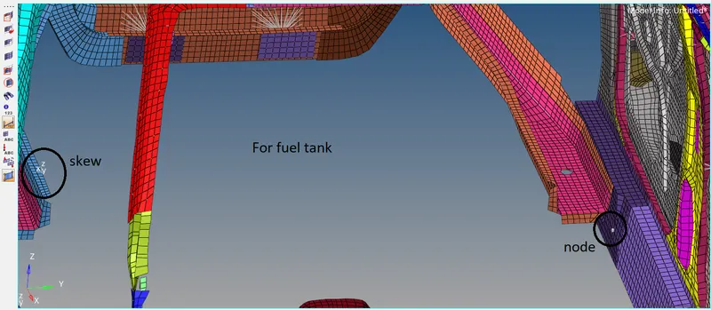
Similarly, create moving skew at the shown places and select the displayed nodes and the skew opposite to the node in the output blocks for requesting output at the B pillar and the fuel tank.
Also, we have to find peak velocity of inner node of the door. Now create moving skew at the shown place in the door component.
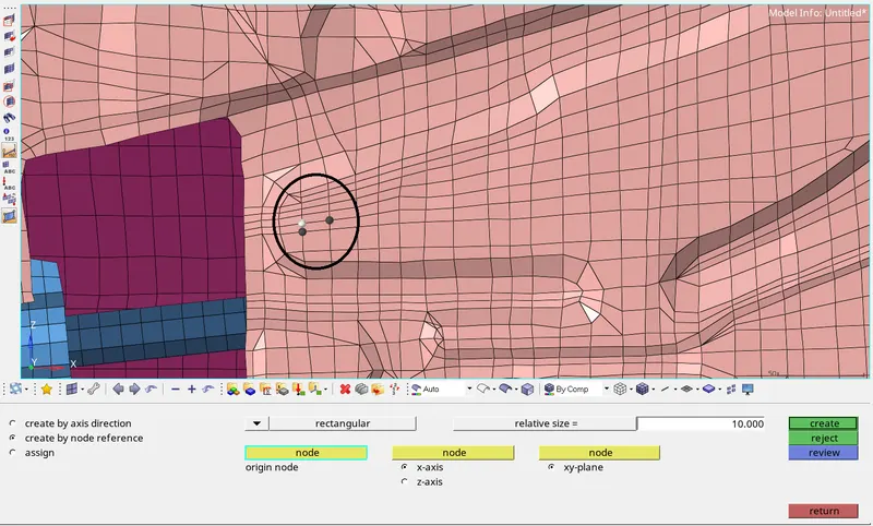
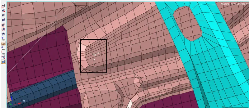
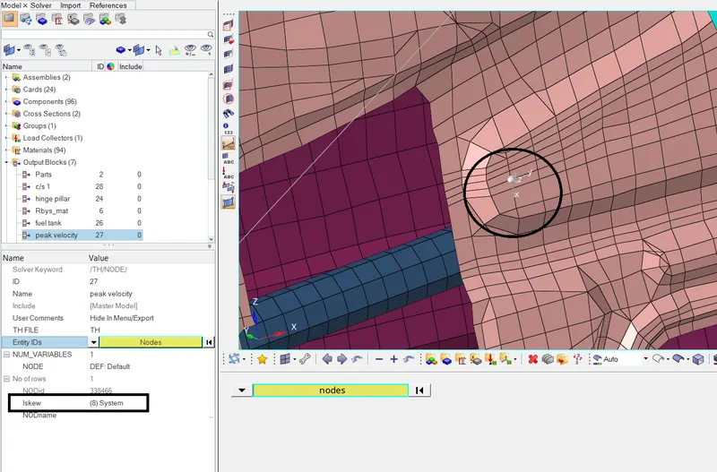
Now go to Model browser > Output Blocks > Create. Rename it to peak velocity. In the Entity IDs selector, select the same node which was the origin of the defined skew. In the Iskew selector, select the
moving skew which we have created on the door component. The output request for peak velocity is completed.
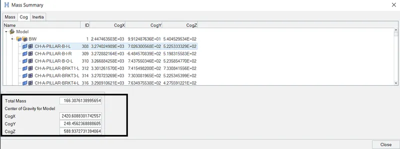
Now we need to achieve total mass of the reduced model equal to full scale model of 700 kg. To check the mass of the model and the cog, go to Tools > Mass details > Mass, inertia, cog > cog. As seen, the
reduced car model have mass of 166 kg. We need to add the mass differnce which is 534 kg. Add mass at appropriate places in such a way that cog shifts near the red cross member.
To add mass, go to Solver browser > Create > ADMAS.
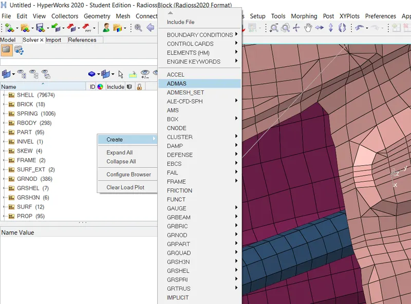
Set the Mass type to 0 which will add the entered mass value to each entity selected by the user. Right click on the grnd_id and click on Create. Set the Entity_IDs selector to nodes and select few nodes on
the cross member and click on proceed. In the Mass tab, enter the value of mass to be applied to each selected node.
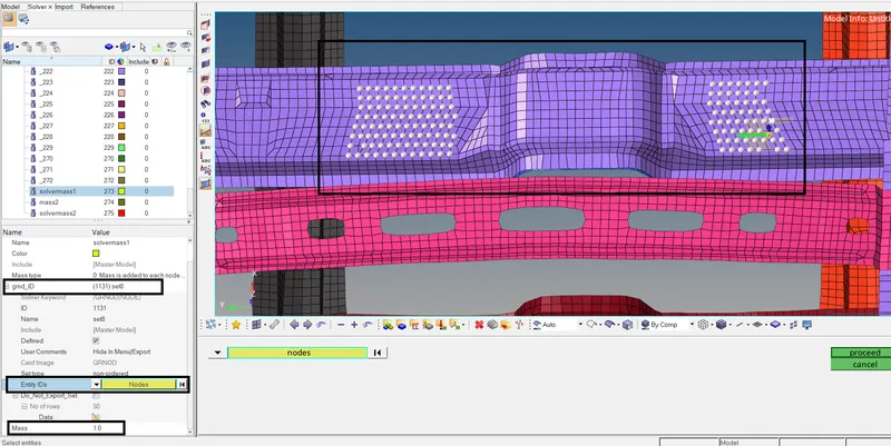
Repeat the procedure to add mass at required places to achieve the total mass of 700 kg with cog located at the red color cross member.
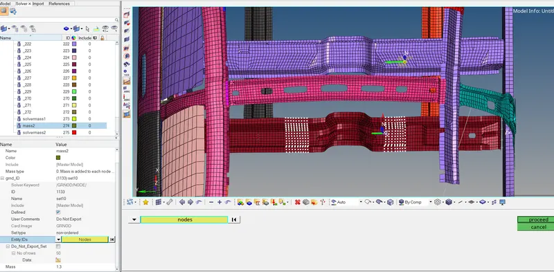
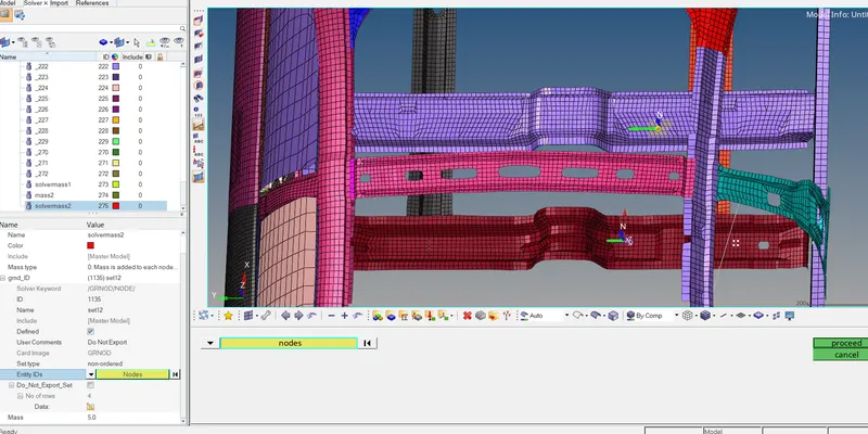
Now check the total mass and the location of cog. Go to Tools > Mass Details > Mass,cog, inertia > cog.
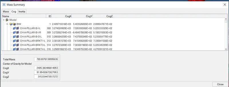
Required mass of 700 kg is achieved. To chech the location of cog, go to Geom > nodes and enter the coordinates of cog seen in the above Mass details. As seen below, the cog is located in proximity of the
centre of the cross member which is somewhat acceptable.
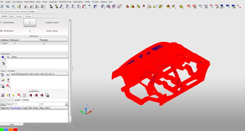
The model is checked for any penetrations and intersections using Hypercrash. None are found.
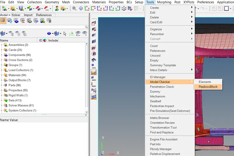
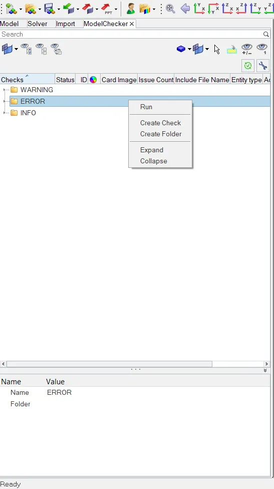
Now we can run the model checker and then finally start the simulation. Go to Tools > Model checker > RadiossBlock. Right click on ERROR andhit Run. No errors are found.
To run the simulation, go to Analysis > Radioss. Click on save as option to define the path to save the files. Click on include connectors and click on Radioss. The simulation will start running.
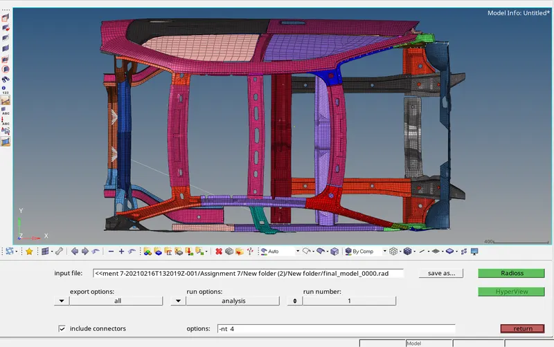
The simulation is completed with Normal Termination.
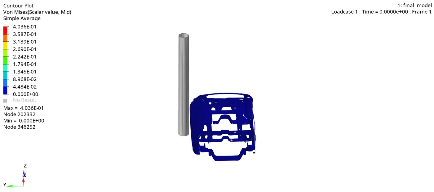
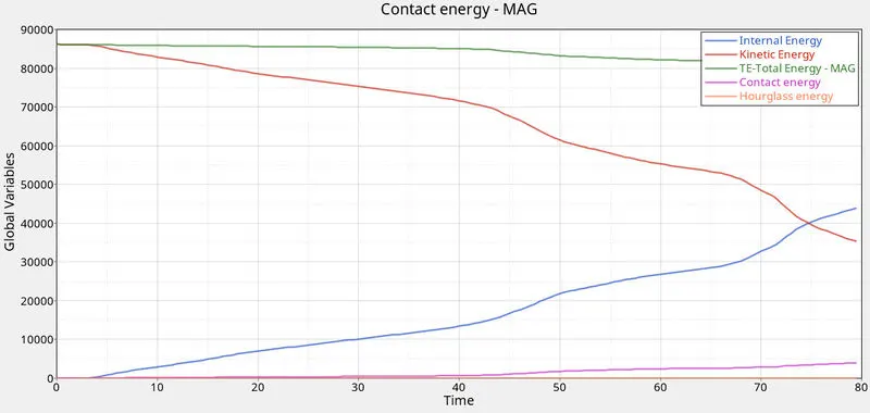
As seen above, the kinetic energy is maximum before impact which starts decreasing as soon as the car hits the rigid wall. As the deformation takes place, internal energy increases as kinetic eneergy is
converted into internal energy as the model deforms. A part of total energy is used by contact energy so a decrease in total energy is observed as contact energy increases. Mass error is 1% which is
acceptable.
Now we can plot the sectional force in the cross members.
- Sectional forces in the cross members:
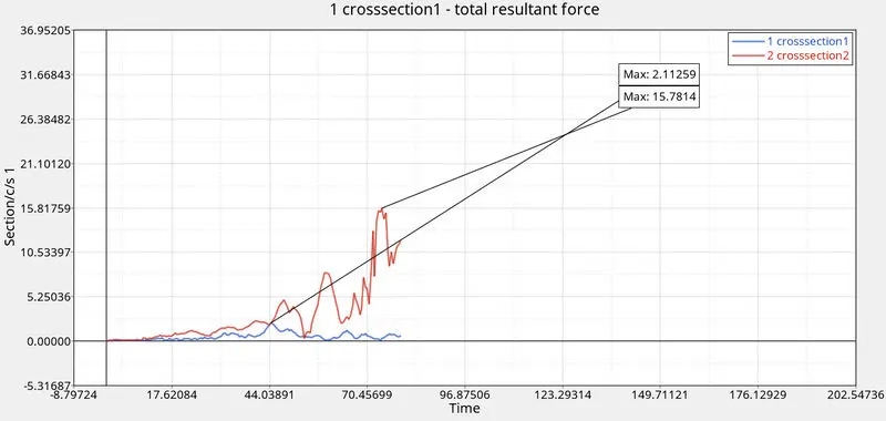
The cross member which is in lie of pole and connected to B pillar experiences maximum force as compared to the other cross member.
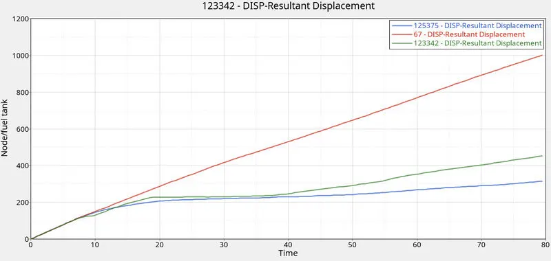
The intrusion at the fuel tank is 1169.20 - 315.16 = 854.2 mm
At Hinge pillar : 1340 - 1001.17 = 338.83 mm
At B pillar: 1328.2 - 452.34 = 875.86 mm.
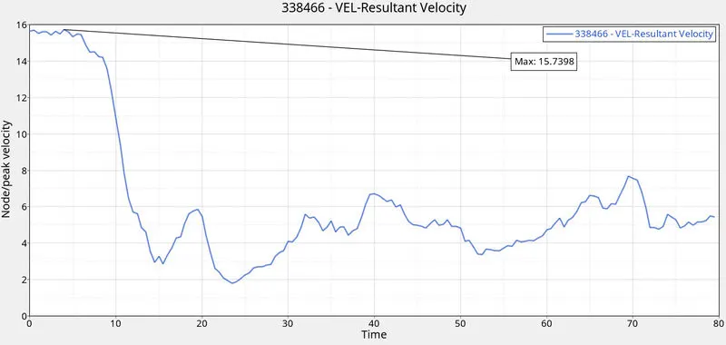
- Peak velocity of inner node is found to be 15.73.
- Fuel Tank intrusion:
To reduce the fuel tank intrusion, we can either add some reinforcing structure after the B pillar which will absorb the energy after impact or we can change the material which will have greater stiffness so
that the displacement observed is minimum. Changing the thickness of the components may help in reducing the intrusion.