Assignment 7-Side Pole Crash Simulation Challenge
SIDE POLE CRASH SIMULATION OF DODGE NEON BIW :
Aim :
To perform Side Pole Crash simulation of Dodge Neon BIW structure (reduced model) using Hypercrash/Hypermesh to preprocess and Radioss to solve.
Objective :
- To check unit system and follow [Kg mm ms].
- To create appropriate interface,friction 0.2 and recommended parameters.
- To make sure of no penetrations and intersection.
- To create rigid wall (pole) with friction 0.1.
- To compare the model weight with the full scale 300k nodes model and use added masses to reach target weight 700kg while getting CG about the required range.
- To apply Initial velocity 35 mph.
- To ensure good quality of model.
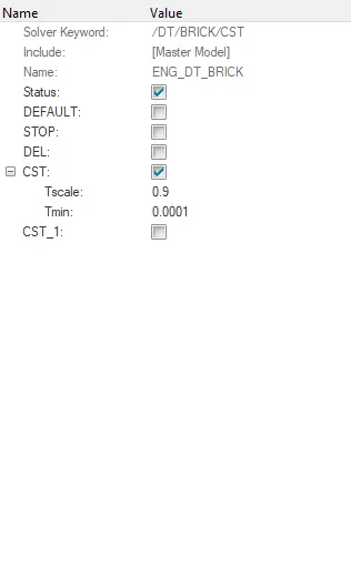
- Setting Time-step :0.5 microseconds.
- Setting Runtime 80 ms.
Procedure :
Crash Test :
A crash-test is a form of destructive testing usually performed in order to ensure safe design standards in crashworthiness and crash compatibility for automobiles or related components. To test the cars safety performance under various conditions and during varied types of crashes, vehicle manufacturers crash test their cars from different angles, different sides and with different objects, including other vehicles.
The most common types of crash tests are listed below :
- FRONT IMPACT TEST
- FRONT OFFSET IMPACT TEST
- SIDE IMPACT TEST
- ROLL OVER TEST
Side Impact Test :
This is a severe test of a car’s ability to protect the driver and passenger’s heads in a side impact. As the loading on the car is so localised, deformation can be very high and the pole can penetrate deeply into the passenger compartment. Without effective protection, the pole would strike the head resulting in serious injuries. Head protection airbags – often curtain airbags mounted above the side windows but sometimes seat-mounted thorax/head airbags – have become a common solution but great care is needed to ensure effective performance of such devices.
The vehicle is positioned at a right angle in the direction of movement or at a small angle away from the perpendicular.
Case setup :
1. Unit system check :
Firstly, Import the _0000.rad file to the Hypermesh window and then go to model browser >> Cards >> BEGIN cards >> See the Unit system followed and set it to Kg, mm, ms If there are any deviations in the current unit system followed.
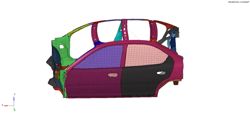
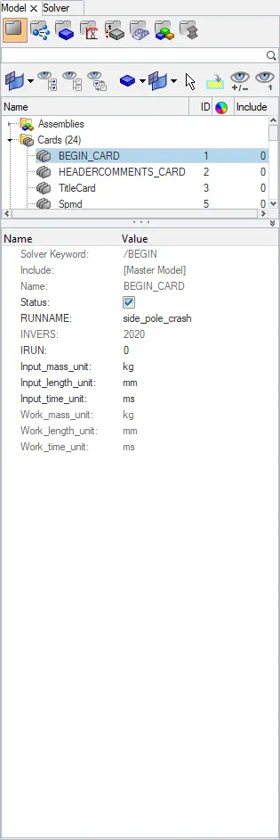
As we can see that the unit system followed in this model is Kg,mm and ms which is the preferred unit system.
This can also be viewed by opening the _0000.rad file in the notepad in which the Unit system which is followed in the current model will be displayed.
Check Penetrations & Intersections :
Now, we should check for presence of any initial penetrations or intersections in the given model. For this we can do the check in either Hypermesh or Hypercrash and we prefer Hypercrash for this since we again have to do mass balancing in the model, so choosing Hypercrash would be easier to visualize the model.
Open the Hypermesh >> Applications >> Hypercrash >> Import the .rad file >> Go to Quality >> Check all solver contact interface.
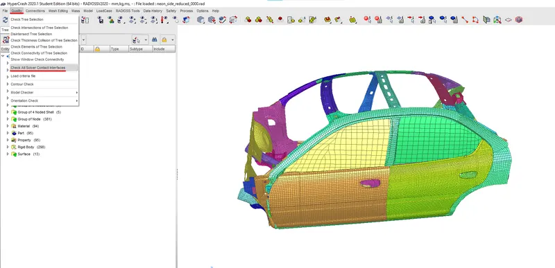
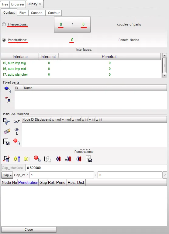
As we can see that the model is free from any penetrations and intersections.
Mass Balancing :
The model should have the total mass of around 700Kg and also the Centre of Gravity should be somewhere near the driver seat in the middle. Since the model has been completely reduced for the side pole impact some of the major components were missing and so the location of COG won't be precise however we can add weight to the model and make the COG to be in the most realistic position. Also the orientation of the COG along the z-axis is not considered here as we don't have the complete model.
Now, go to Hypercrash >> Mass >> Mass Balancing = This will give the total mass of the model and the current location of COG in the model.
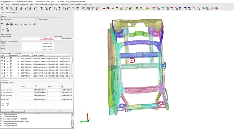
As we can see that the total mass of the model is about 166.3 Kg and the location of the COG is not very realisitic in the given model.
So, we should add mass to the model at several parts to meet the required total mass of 700Kg approx. and that would change the COG location. It has to be done in such a way that the mass addition should align the COG in the most realistic location.
For mass addition, Go to Load case >> Added mass >> Type 3 ( used to add mass distributed to all nodes in the selected parts ). We can add mass to the Left and right side fuel tank support, Driver and Passenger seats, B-pillar cross member, Dashwall, Leg space of driver and passenger.
With all the added mass, the COG would be altered accordingly.
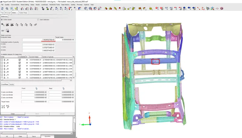
Hence, the total mass has reached the required 700 Kg and the location of COG is altered accordingly.
Initial Velocity :
The Initial velocity should be applied in an axis such that the side of the vehicle should hit the pole in the crash. So, the Initial velocity of 35Mph which is 15.6464 mm/ms has to be applied to the whole model in the Y-axis. This would make the model to hit the rigid pole sideways.
Hypercrash >> Load case >> INIVEL >> Type : Translational >> Vy : 15.6464 and select all the components as the slave to the rigid pole.
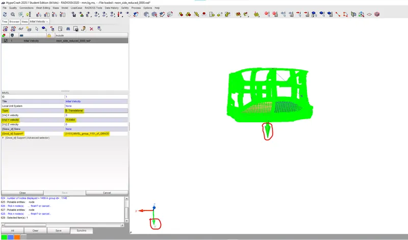
We can see that the Initial velocity has been applied properly to the model along the Y-axis. Now, we can Export the model and Open the same in the Hypermesh window for further case setup.
Rigid Pole creation :
Now, we have to create the Rigid wall (Cylinder) which depicts the pole in this case of simulation. To create the Rigid wall, go to Hypermesh >> Solver >> Right click & create >> Rigid wall >> Cylinder.
In this case, we need to select a node which is slightly away from the most outer node in the B-pillar since the rigid pole shouldn't be touching the B-pillar initially.
Here, the Cylindrical Pole should be of diameter 254mm ( as per the Standards in Crash testing ) and then it should be of type sliding with friction. Provide Friction as 0.1 and the Normal should be along the Z-axis. The node selection of rigid wall should be made in such a way that it covers the whole height of the model. Provide Dsearch as 1000mm.
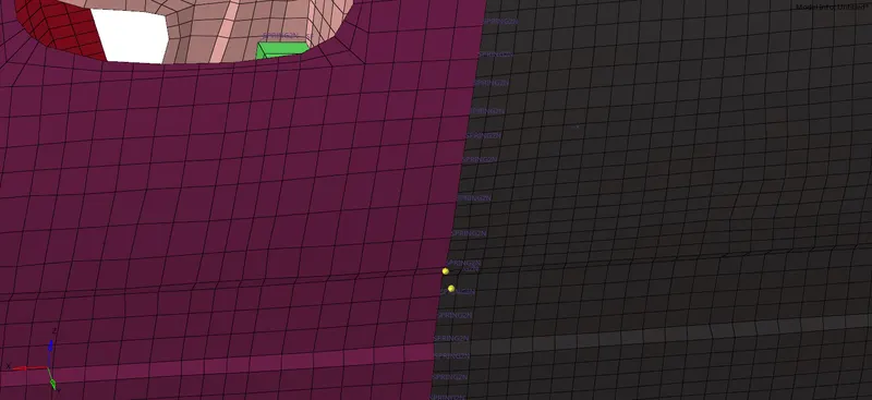
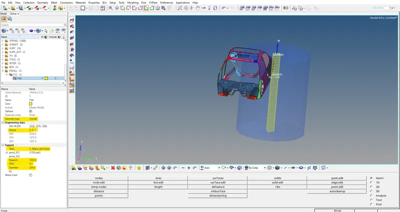
As we can see that the rigid pole cover the complete model of the vehicle and all the parameters were set properly. Now, we should create the self contact Type 7 interface for the model.
Type 7 Interface :
In model window, delete all the previously created Interface and rightclick & create >> Inter >> Type 7. Here, we need to select all the components as both the Master and the slave. Once they are selected, we need to fix all the other parameters like Igap, Idel, Gap min, Stmin, Inacti etc., to the required parameters.
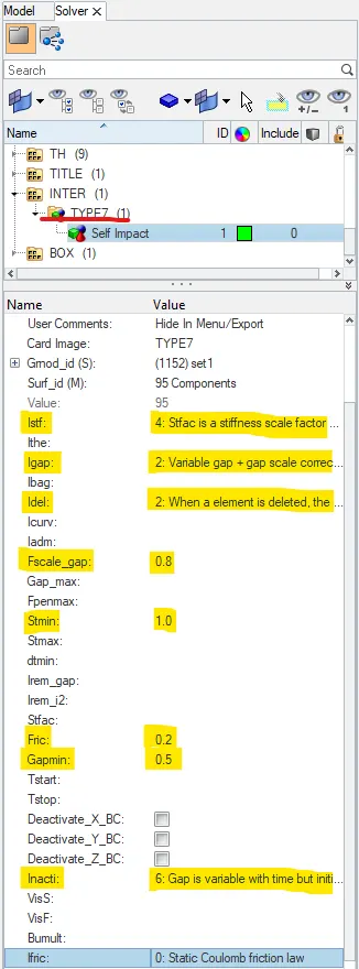
Click on review to check whether the selection of components for Self Impact has been done correctly.
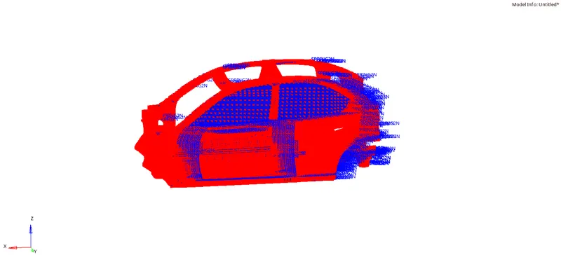
Now, we can go ahead and set all the requested output parameters like creating cross sections, Intrusion springs etc.
Cross sections :
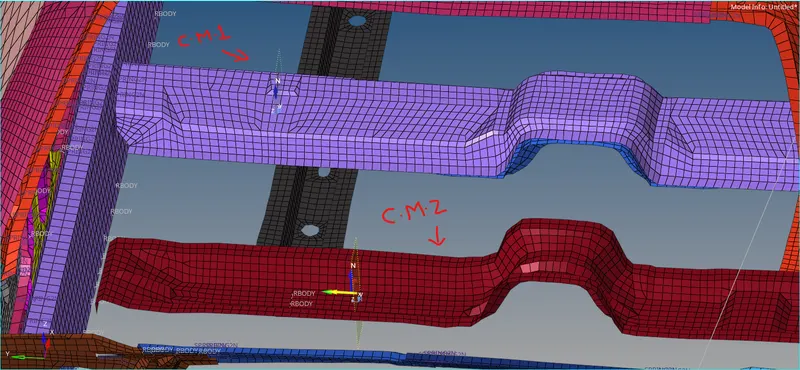
We need the cross sectional forces on both the cross memebers, One near the Driver seating and the other one near the B-pillar. Hence we should create cross sections on both these cross members. Before creating the cross members, we need to create Moving frame of reference for those cross section elements. So go to solver browser >> right click and create >> Frame >> Mov.
Now, select the frame by node reference option and select the Origin node. The node selection should be done in such a way that the plane of reference should be parallel to the rigid pole.
Once the frame is created, then Right click on solver browser and create >> Sect >> Sect and select the created Moving frame in the Frame ID column for both the cross members seperately. Then select the Cross section elements in GrshellID. Set DeltaT to 0.1 and the Alpha to 0.628 (default).
Thus, the cross sections has been created to study the forces crossing in these cross members.
Intrusions in Hinge Pillar, B-Pillar, Fuel tank nodes :
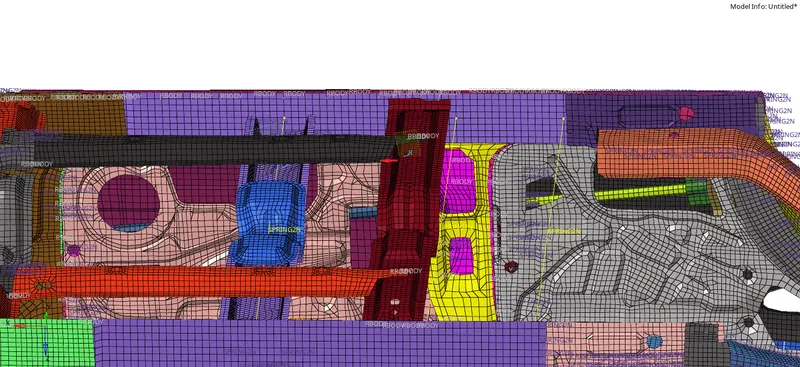
To study the Intrusions on the nodes of Hinge pillar, B-pillar and Fuel tank nodes, we can do it by two ways. Either we can create a frame of reference for those nodes locally and request for the TH/Node to study the Intrusions on those nodes according to those frame of reference. Or we can create a Spring element across those nodes with very less mass and stiffness such that their output on elongation would give the intrusion on those nodes. Now, we will create the Spring elements on those nodes and the nodes opposite to those parts.
Go to Hypermesh >> 1D >> Springs >> Spring 2D >> Select the Nodes and create.
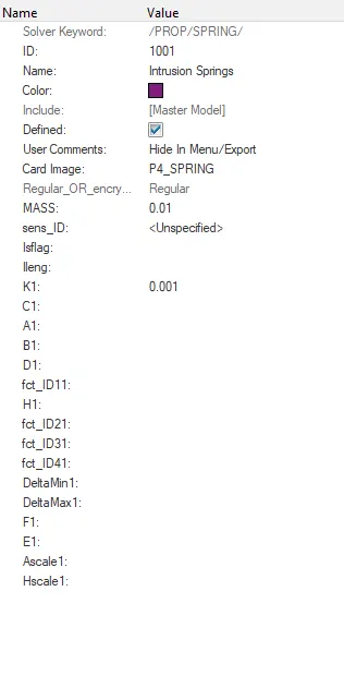
Once the Springs are created, We should define the Spring property for them. Go to model browser >> right click >> Create >> Property >> P4_springs >> Mass : 0.01 >> Stiffness : 0.001.
Now assign this property to those spring elements. On requesting the output for those spring elements, we would get the intrusions on those nodes respectively.
Peak velocity on Inner door node :
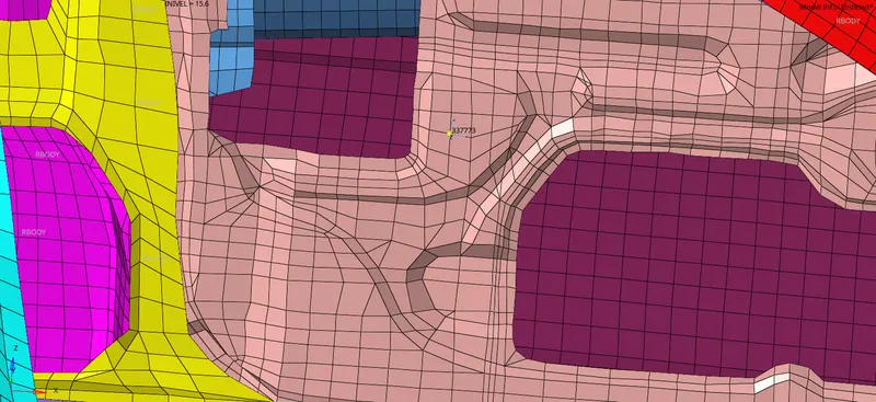
Now, we need to create a skew for the Inner door node ID 337773. Go to Solver browser >> Right click and create >> Skew >> Mov >> By node reference.
Select the desired node as origin and define the X-axis and XY plane accordingly.
Other setups :
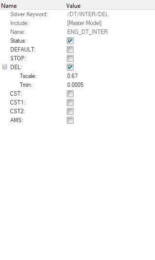
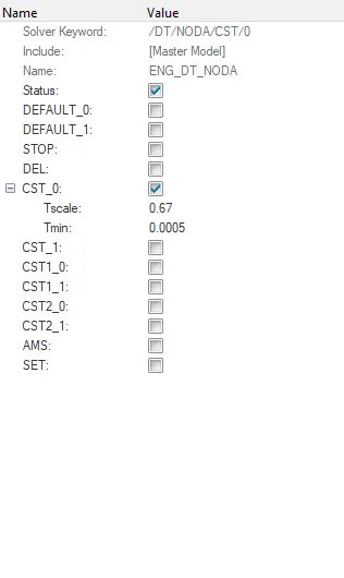
Now,we can set all the other parameters like Total run time, Minimum time step, Tfreq for the animation files etc. With all those cards setup then we can request for the Output files.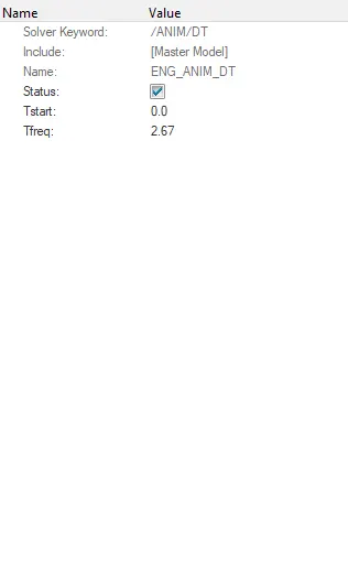
Output requests :
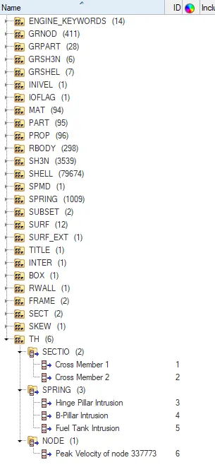
1. TH/Cross section :
Now, we shall request the required outputs. Solver >> Right click and create >> TH >> Section. Now, select the created cross sections, and request for the outputs seperately for two cross members.
2. TH/Spring :
For the Intrusion of nodes on Hinge, B-pillar and Fuel tank, Solver >> Create >> TH >> Spring. Select the Spring element created in the Element section and seperate request has to be done to get the results on all the three nodes in the respective parts.
3. TH/Peak velocity :
Now, for this Peak velocity of node 337773 of the Inner door, we need to create TH from the Model browser. Model Browser >> Output Block >> TH >> Node. Select the corresponding Node and Select the Skew we created in the ISkew ID.
These are the required outputs from this simulation :
Final Model Check :
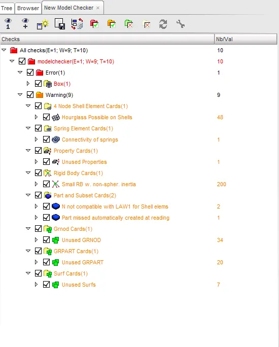
Once all these case were setup, we need to check whether there are any errors in the model. So export the file to Hypercrash. Now, Open the file,
Quality >> Run model checks.
Some warnings and error pop up when the check is done, those can be easily fixed by Automatic Fix error option.
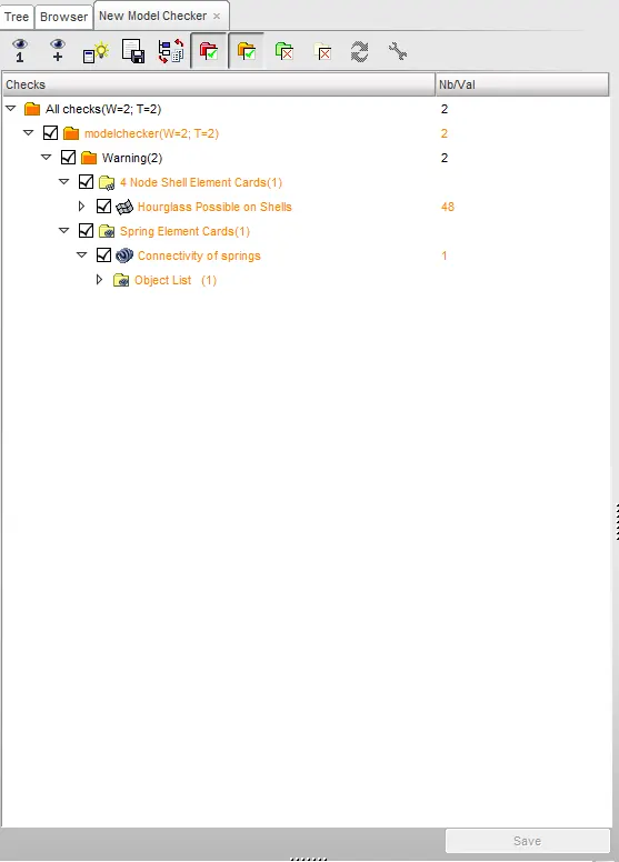
With all the errors cleared, we can now run the simulation. Export this file to Hypermesh and Run the simulation.
Outputs :
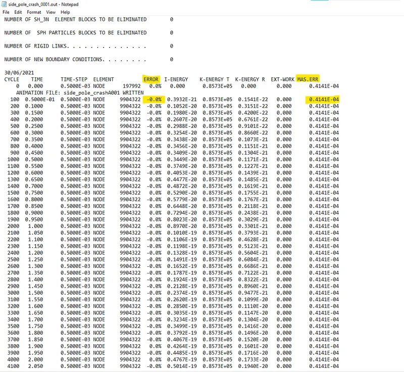
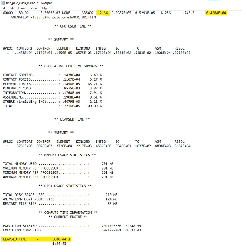
Go to Hypermesh >> Analysis >> Radioss >> Include connectors >> Options : -nt 4. Then click on run to start the simulation. So, Initially the energy error was 0.0 % and it reached the maximum of -2.6 % and similarly the Mass errors was about 0.41 E-04 and reached upto 0.42 E-04.
These values were very well within the range of acceptance and hence we can see the simulation and the results in Hyperview and Hypergraph 2D respectively.
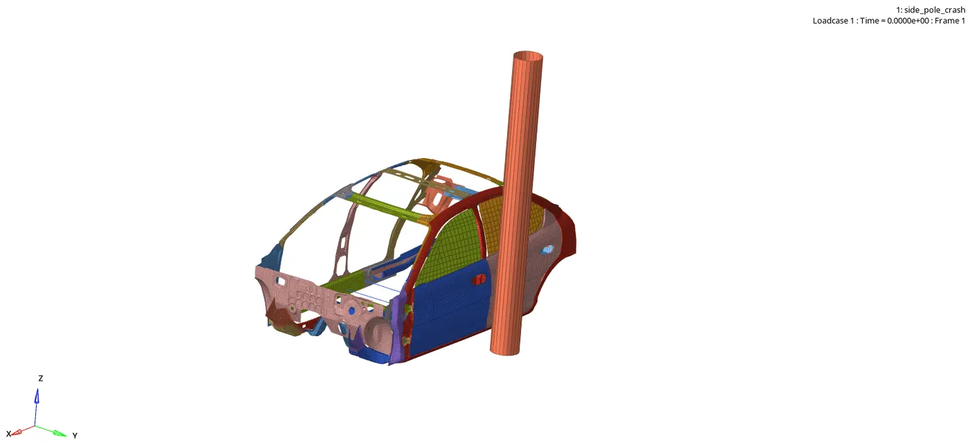
Animation results :
Displacement :
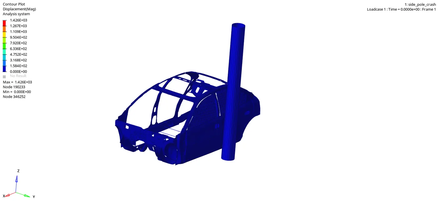
We can observe that the maximum displacement has reached upto 1426mm. This is due to the fact that the model has been reduced to BIW and it doesn't have more parts like Seat arrangements, Engine block, Suspension and wheels etc.
Von-mises stress :
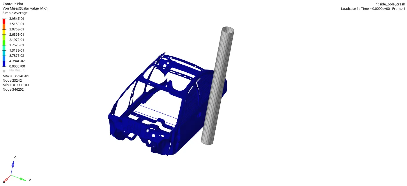
The maximum stress produced in the crash is about 0.3954 kN/mm^2. The stress distribution is quite smooth however there are certain areas where we can see some stress concentration more near the B-pillar area where it is the first point of contact in the crash.
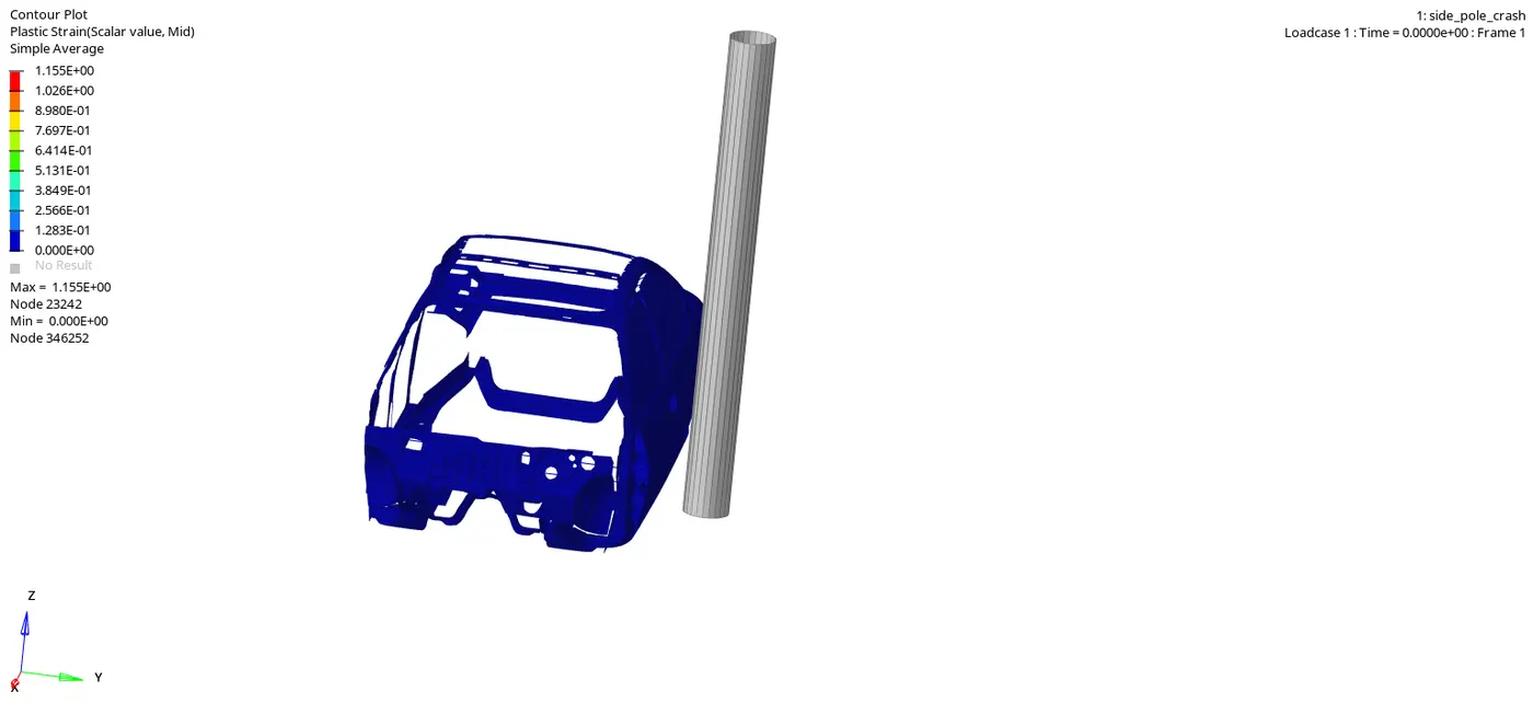
Plastic Strain :
Global variables :
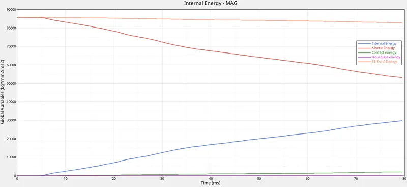
We can see that the Kinetic energy starts at maximum and reaches the minimum point at the end however the Internal energy has started at minimum and reaches the maximum value at the end.
The Hourglass energy is almost non existent due to the fact we've used QEPH elements in our model.
The total energy almost remains constant throughout around 85000 Kg*mm^2 / ms^2. But there are slight deviations in the end due to the presence of Contact energy, which are formed when the elements contact with each other while deformation.
Intrusions on Spring elements :
Hinge Pillar :
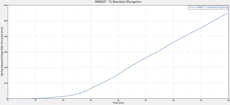
The deformation on the Hinge Pillar node is around 550mm.
B-Pillar :
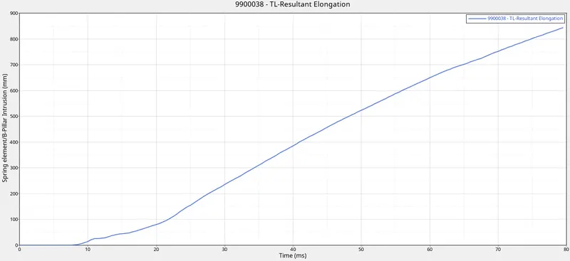
In the B-pillar node, the deformation is around 840mm which is greater than that of the Hinge pillar. This is because the major impact happens at the B-pillar and so the forces were transmitted to the B-pillar and the presence of rigid pole is exactly near to the B-pillar.
Fuel Tank :
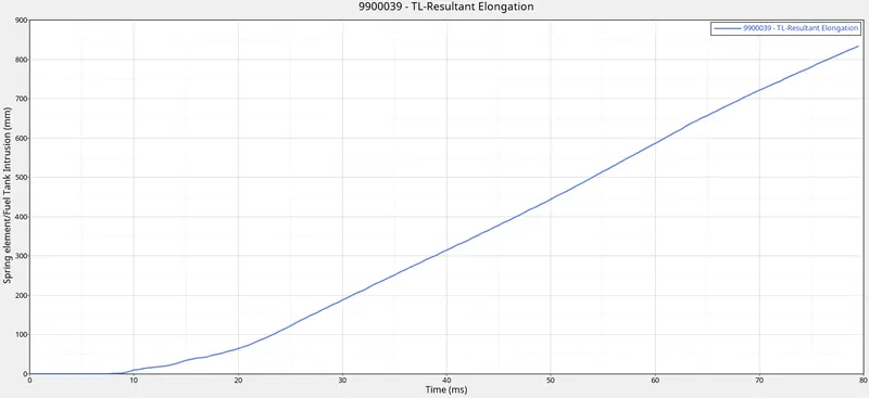
The deformation around the Fuel tank is around 820mm which is greater than the Hinge pillar however smaller than the B-pillar node. But the fact is, this much of the deformation in the node near the Fuel tank area would damage the Fuel tank and causes leakage of Fuel in the crash which would increase the severety of the crash as the fuel might get ignited and cause explosion.
So, To avoid such a level of deformation and to reduce the severety we can add some cross members in the Fuel tank region which would help the energy absorbtion causing less deformation.
Cross Section Forces :
Cross Member 1 (Hinge Pillar) :
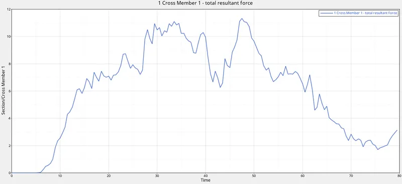
We can see that the maximum cross section force in the Cross Member 1 is around 11kN. While crashing, most of the forces would be absorbed by the B-pillar and its cross member and so lesser forces were transferred to other parts.
Cross Member 2 (B-Pillar) :
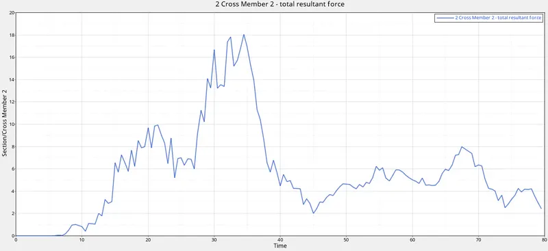
Here we can see that the Maximum force experienced is around 18kN which is more higher than the other part. This is because B-pillar is the major part of contact in the crashing and more forces travel across it. The absence of floor panels,seats and other reinforcements has made the condition even more prone to get more forces.
Peak Velocity on Inner door node 337773 :
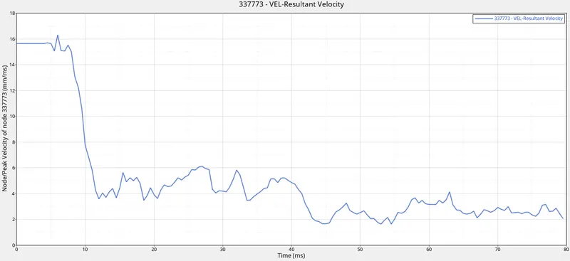
We can see that the Velocity of that node is constant upto 6ms which is 15.64 mm/ms (the applied Initial Velocity). Now after 6ms, As the crash happens, there is a steep decrease in the velocity of the node and then it progresses and it keeps on deviating. This deviation might be due to element deformation as the crash progresses due to inertial forces, the velocity is fluctuating and then it greatly reduces around the end of the run time.
RESULTS :
Thus, the Side Impact Crash simulation has been carried out successfully on the reduced BIW of the Dodge Neon vehicle using Hypermesh/Hypercrash and Radioss.
INFERENCE :
We can see that the Energy error and Mass error were well within the range of acceptance. There were a lot of Intrusions on B-pillar which is mostly due to the fact the rigid pole is right next to it and the absence of several parts in the model.
However, the higher intrusion near the fuel tank area should be considered as it increases the risk of causing severe damage. There we can add on some cross members to absorb more forces which might solve the concern.
Similarly, Anti-intrusion bars can be added in the Door, which would greatly help in reducing the velocity fluctuations and the intrusions which thereby helps to reduce the damage. However adding such structures would add mass to the vehicle, so materials should be selected properly to avoid over weight yet not compromising on the structural rigidity. Certain alloy metals, Aluminum, Chrome alloy etc can be a great choice in such cases.