SIDE CRASH ANALYSIS OF AN AUTOMOBILE BIW ASSEMBLY
SIDE CRASH ANALYSIS OF AN AUTOMOBILE BIW ASSEMBLY
AIM:
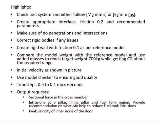
The objective of this project is to study and analyze the behavior of the BIW assembly of an automobile during side crash when the car hits a stationary rigid pole from the side.
INTRODUCTION:
Crashworthiness is the ability of a structure to protect its occupants during an impact. This is commonly tested when investigating the safety of aircraft and vehicles. Depending on the nature of the impact and the vehicle involved, different criteria are used to determine the crashworthiness of the structure. Side pole impact is a very severe test of a car’s ability to protect the driver’s head. As the loading on the car is so localised, deformation can be very high and the pole can penetrate deeply into the passenger compartment. Without effective protection, the pole would strike the head resulting in serious injuries. Head protection airbags, often curtain airbags mounted above the side windows but sometimes seat-mounted thorax or head airbags have become a common solution but great care is needed to ensure effective performance of such devices. Side impact collisions are a particularly severe and harmful type of crash for vehicle occupants. Depending on the severity of the crash, side impacts can be involved in up to 35% of road trauma and particularly noteworthy in fatal crashes
There are 2 types of side pole impact tests.
1. 254mm diameter pole impact on a 75° oriented car, travelling at 32 km/h, also called “oblique pole test”. The test configuration is defined in FMVSS 214 regulation.
2. 254mm diameter pole impact on a 90° oriented car, travelling at 29 km/h. It is applied in Euro NCAP, KNCAP and ANCAP.
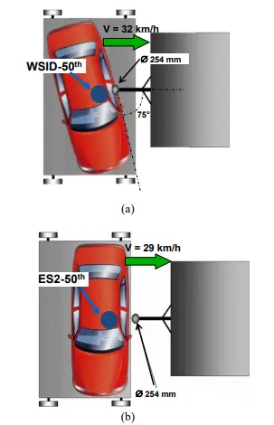
Fig: Types side pole impact test.
PROCEDURE:
1. Import the given model to the Hypermesh Radioss profile so has to run the model in Kg,mm,ms unit system.
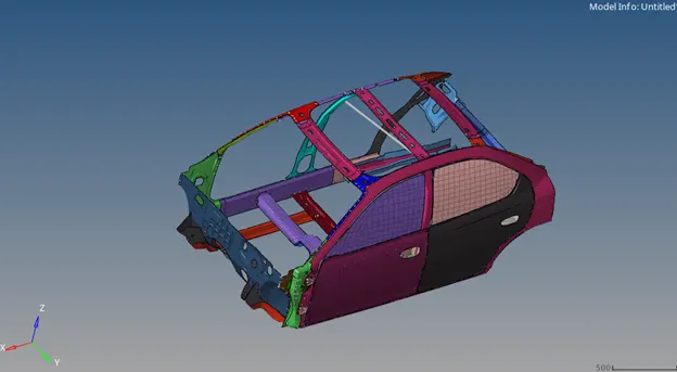
Fig: Imported Model.
2. Check the interfaces and create a new self-contact interface of Type 7 with recommended properties and with friction of 0.2. Delete the other contact interfaces.
3. Check for penetration and intersection for component and group level and make sure there is no collision in the model.
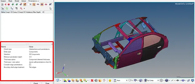
Fig: Penetration and Intersection check.
4. Check the rigid bodies and connections using find connectivity option and make sure there aren’t any flying parts (Free parts) in the model.
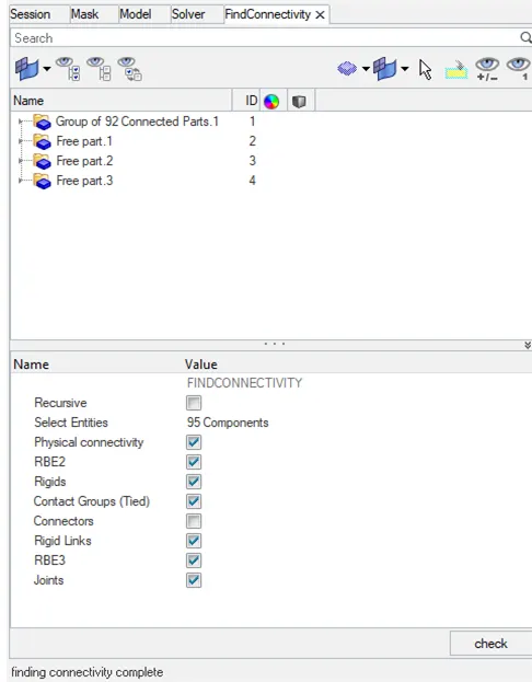
Fig: Connectivity check.
5. The model had 3 free parts, so connect those parts with the neighboring parts using cluster RBE2 elements.
6. Open the solver browser and create a rigid pole (Rwall_Cylinder) of diameter 254mm with friction 0.1 normal to Z direction as shown. The pole must be situated near to the B pillar and enter the Y distance as 1050mm, set the search distance to 1000mm.
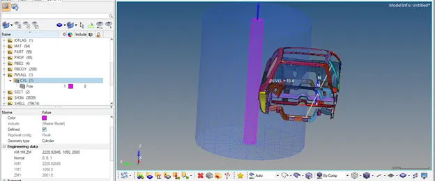
Fig: Rigid Pole (Wall).
7. Apply the Initial velocity of 15.6464ms (35mph) to all the nodes normal to Y direction.
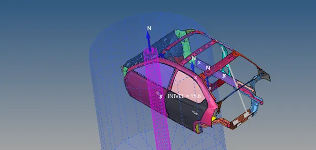
Fig: Initial velocity.
8. Create the frames (moving type) on rocker part near the B pillar and near the door.
9. Create the sections using the created frames as shown in order to obtain the sectional forces at the prescribed locations. Make sure that the section plane is parallel to the rigid wall or direction of force propagation. While creating the section enter the DeltaT as 0.1, alpha as 0.67 and set Iframe to 12.
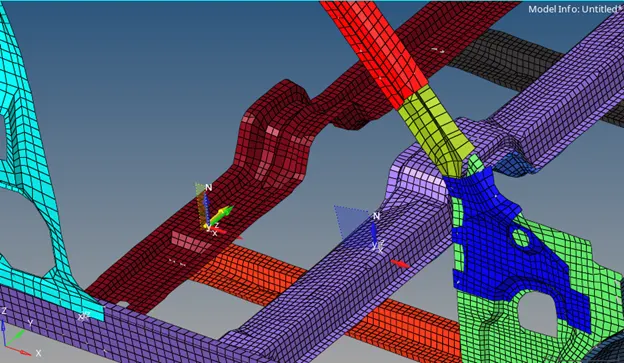
Fig: Created sections.
10. Open the engine keyword set the Run time to 80ms in the run card.
11. Crate animation cards like ANIM/MASS, ANIM/VECT, ANIM/ELEM, ANIM/NODA, set ANIM/DT Tfreq to 2.67 (30 frames).
12. Set the time step of 0.0005ms (0.5microsec) in the DT card and set all DT/SHELL, DT/BRICK, DT/INTER, DT/NODA with constant time step (CST). For Brick and Shell set Tscale value to 0.9 and for rest of the cards set to 0.67. Select the required parameters from the card.
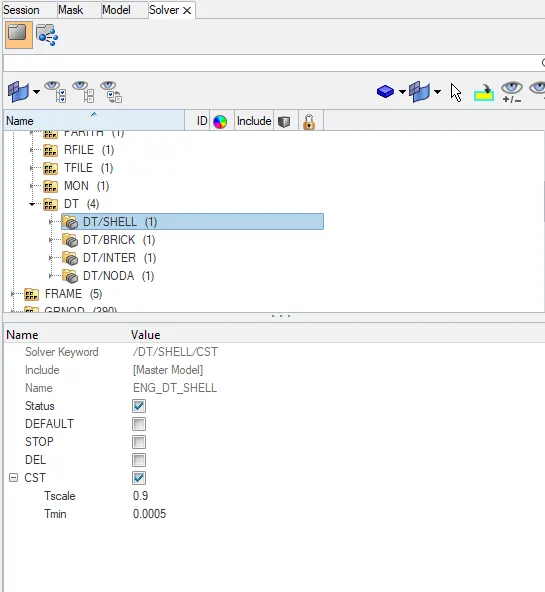
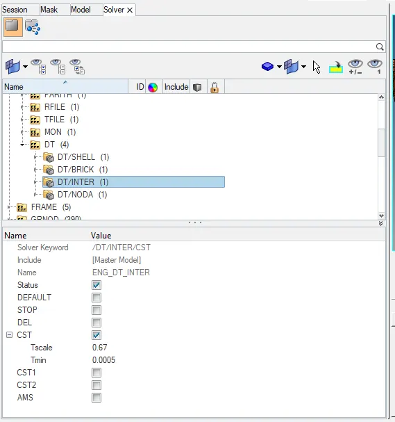
Fig: Output request.
13. The output requests will be created using TH card, create a TH card for the Sections, Rwall, Part, select the created credentials and request for the Default variables.
14. The TH nodes will be created in order to measure the Intrusion on the dash wall. So the nodes of the rocker is selected and separated TH cards are created, select the nodes and frames in the card. Since the output required is only with the Displacement so select the variable as displacement in x,y,z.
15. The peak velocity at the node 337773 will be acquired by creating the TH card using the node and frame created on the same node.
16. Check the Mass and COG of the model using Tools- Mass details – Mass, cog and Inertia. The COG of the model must lie approximately behind the Seat location (At SeatReinforcement beam).
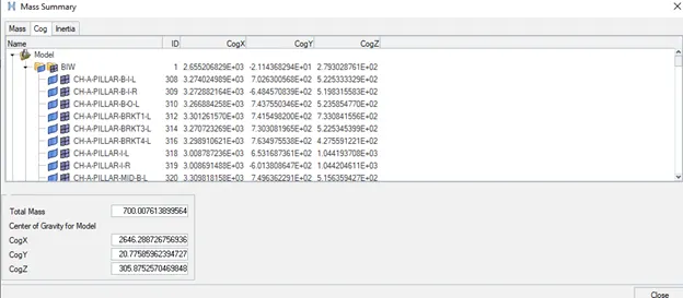
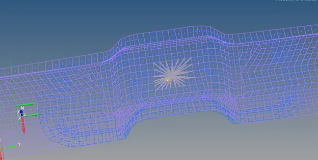
Fig: Mass summary and COG.
17. In order to obtain the CG at the required location the additional mass has be added to the model limiting the total weight of the model to 700kg.
18. To add the mass create ADMAS select the mass type as 3 Additional mass distributed on the part group, enter the mass value and select the part. Usually in general case the mass of passenger will be added to the location of the seat as shown. Balance the magnitude to obtain the CG in X and Y axis.
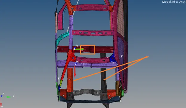
Fig: Mass applied.
19. Finally run the model checker to check the error and potential warnings. Tools- Model checker – Radioss Block – Run.
20. An error of material property appeared which can be omitted. Run the simulation in radios with 4 core threads and Plot the results required.
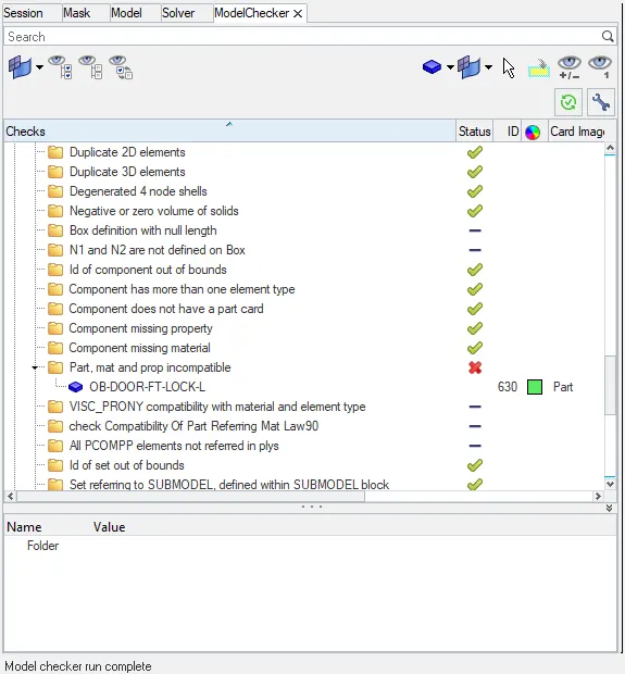
Fig: Model checker.
RESULTS AND DISCUSSION:
Energy error and Mass error:
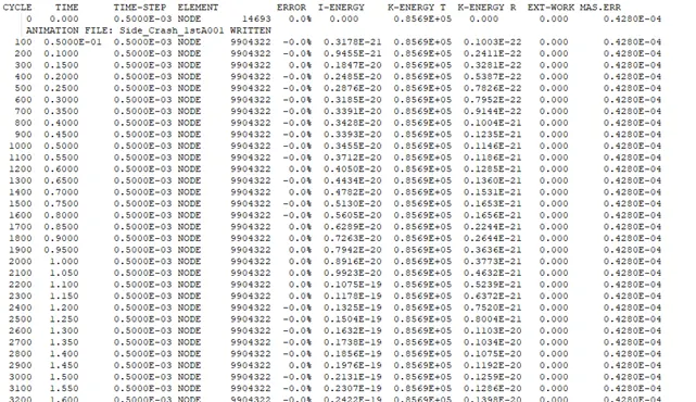
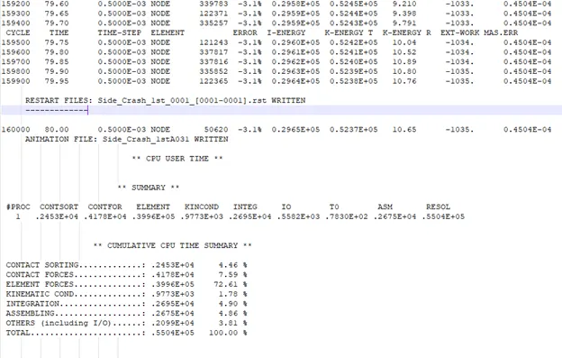
The energy error and mass errors were found to be negligible since the magnitude of errors is in the accepted level. The min Energy error is 0% and maximum of -3.1%, The min mass error is 0.4280E-04 and maximum is 0.4504E-04 (less than 2%).
Displacement:
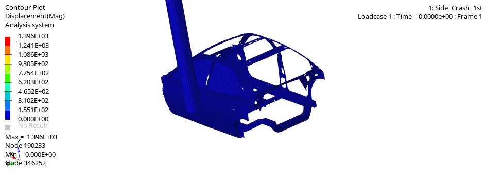
The maximum displacement of overall BIW was found to be 1396mm. The huge deformation of the model is due to the missing components like floor panel and other seating frames and engine compoents.
Stress:
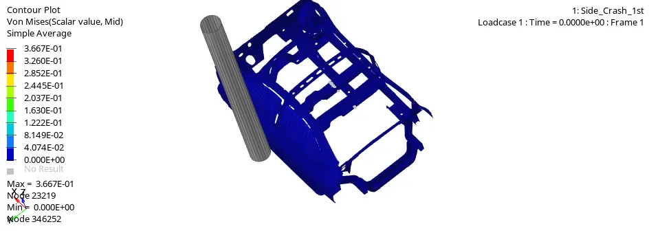
Since the deformation is very high the stress absorbed by the components are very less. The maximum stress on the model was found to be 0.3667 kg/mm2. It clearly defines that the most of the energy was absorbed by the BIW components.
Conatct force:
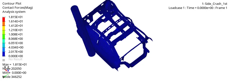
The maximum contact force on the model was found to be 18.15KN. The force is comparitively low since the area of contact between the pole and BIW is very less.
Intrusion:
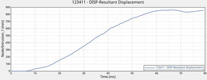
The intrusion on the rocker at node 123411 near the tank location was found to be 860mm. The huge deformation is due to the missing parts like floor panels and reinforcement bars.
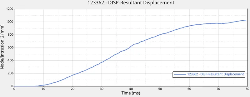
The maximum intrusion or displacement of the node 123362 nearto the B pillar is found to be 1025mm. The deformation is larger than the other intrusion which is due to the position of the rigid pole.
Sectonal force:
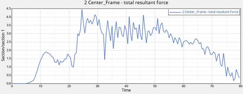
The maximum force recorded on the central frame was found to be 4.4KN. While collision the most of the energy will be transferred to the B pillar and some portion of the impact force will be transferred to the other parts.
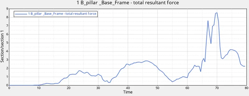
The maximum force on the B_pillar base frame was found to be 8.5KN. The frame took more force since the impact is right infront of the B pillar so more than 40% of the force is tranferred to the frame and the absence of the floor panel will also a significance reason for the huge force distribution.
Velocity:
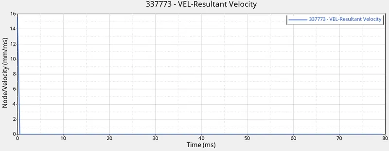
The initial velocity ot the door node 337773 is 15.6 mm/ms and suddenly reduces to zero when the BIW hits the rigid pole. The sudden decrease in the velocity is due to the rapid collision of the BIW to the pole which makes the model to slowdown to rest.
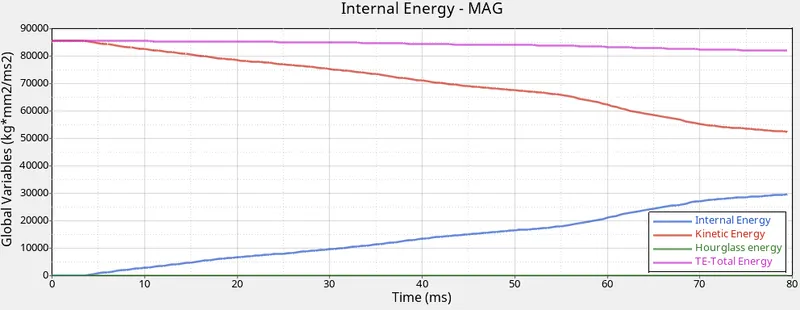
From the output graph we can conclude that the internal energy during the collision increases and the Kinetic energy decreases.The Hourglass energy is negligible and the total energy remained approximately constant throughout the simulation.
CONCLUSION:
- The Energy error and mass error were negliginle and lies within the acceptable level.
- The deforamtion is huge both in B pillar and Tank location due to the missing parts.
- The B Pillar absorbs lot of impact foces than other parts so additional reinforcement of parts are required to ensure more safety of the passenger.
- The hourglass energy is negligible and total enery remained appox. constant throughout the simulation.
- The intrusion of the rocker are pretty high due to the absence of the floor panel otherwise the panel will serve as a support for the rocker during impact.