Assignment 7-Side Pole Crash Simulation Challenge
Aim:- To performe a side pole crash simulation with the given BIW frame in radioss and request for outputs as mention in problem statement.
Neon side crash -BIW
- Check the unit system and either follow [Mg mm s] or [Kg mm ms].
- Create an appropriate interface, friction 0.2, and recommended parameters.
- Make sure of no penetration and intersections.
- Create a rigid pole with a friction of 0.1 as per the FMVSS 214 standards.
- Compare the model weight with the reference model and use added masses to reach the target weight of 700kg while getting CG about the required range.
- Initial velocity - 20mph, as per the standards.
- Use a model checker to ensure good quality.
- Timestep:0.5 to 0.1 microseconds.
- Run 80ms.
Output requests:
- Sectional force in the cross member.
- Intrusion at B pillar,hinge pillar and fuel tank region. Provide recommendations on what can help to reduce Fuel tank intrusion.
- Peak velocity of an inner node of the door.
Solution:-
penetration check:-
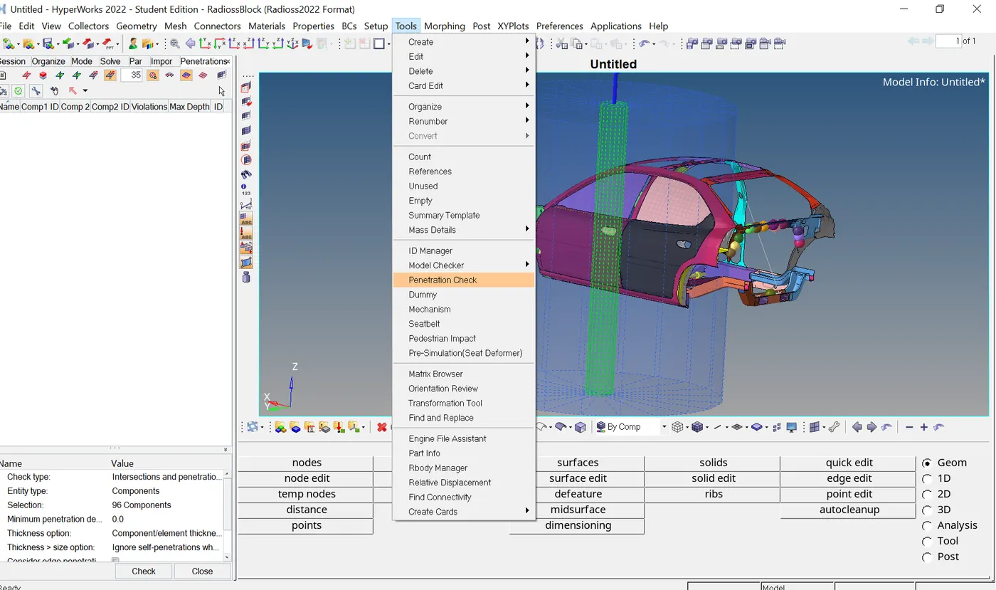
To check the penetration go to tool>penetration check.in the penetration check penel, we will select all the component and click on check commend.The software will check for penetration and display the result as show the below.
Interface :-
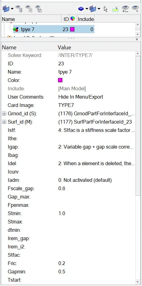
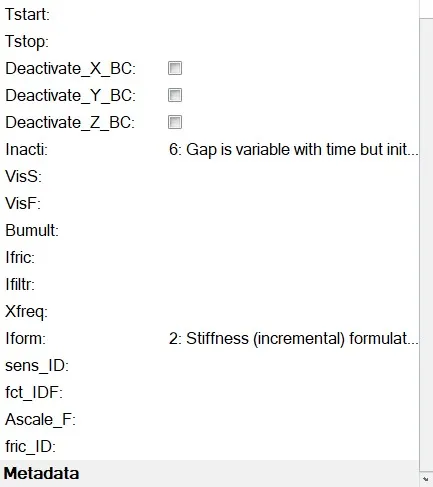
Here we will create type7 interface contact for all component of model. we will go to solver browser >right click and create >inter>type7. under type7 interface,we will select all the component for slave node and master surface in grnod id and surf id respectively.Then will define all the recommended parameters for type7 interface.
Rigid wall:-
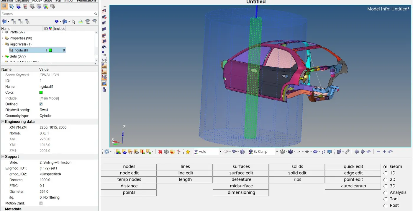
To creating rigid first we create temp node at the side of door the we will go to solver browser and create rwall >cycl,then we select node to create rwall and then give a gap of 10mm the wall must not be connected to the model. The normal of the wall will be in .then we will specify the other parameter as follow.
Initial velocity :-
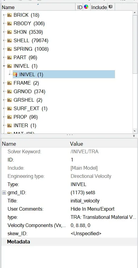
The initial velocity of this model 35mph or 15.646mm/ms. To create velocity card go to solver browser and right click create boundery condition >BCS>inivel and set the value of velocity in y direction as show below.
Section creation:-
- To achieve the result, we will create a cross-section calculated based on a frame of reference. Now first we will create a moving frame on a particular node. Now we have to create a moving frame which is also called the local axis, and we have to perfectly align our local axis to the global axis. Then we create the cross-section.
- To create a moving frame using these nodes. we will right-click and navigate to create >frame >mov. And create the moving frame.
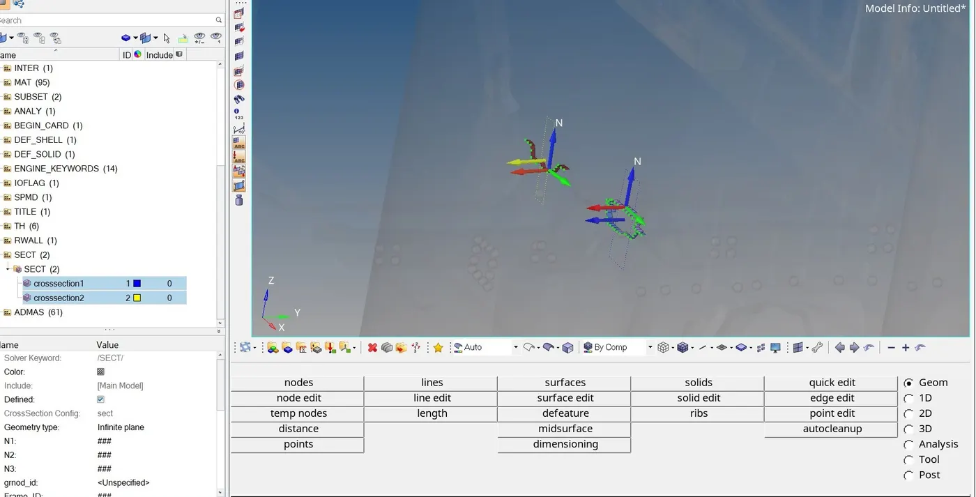
- Now we will create a cross-section for this frame. now we will right-click on the solver browser and navigate to create> sect> sect. In the section plane, we will specify the frame_ID as the moving frame that we create and a delta value of 0.1 as the general value.
Set time step and runtime
To check these parameters in Hypermes, we will navigate to cards under the model browser. To check the run time, we will open ENG_RUN card to see that the model already has the run time in stop as 80 ms. For the run time, we will open ENG_DT_NODA card and we will change the tmin value to 0.0002 ms.
Output request
- peak velocity of the inner node of the door.
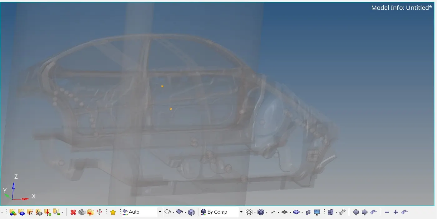
To find the peak velocity at the inner node of the door, we will create a moving frame at the node location by using the same procedure as well used in cross-section creation. Then we will create an output block for the velocity by specifying the node and the frame or skew based on which the velocity is calculated as shown below.
- Intrusion at B-pillar, hinge pillar, and fuel tank.
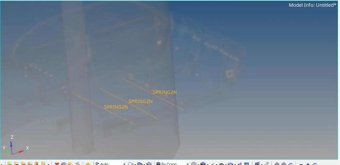
Here, we need to find the intrusion at the B-pillar, hinge pillar, and fuel tank. So to find the result at the specific parts, we need to create spring here as shown below.
Mass Balancing
The BIW model doesn't consist of the exact weight of the vehicle so Additional mass should be added to the BIW model considering the weight of the body after manufacturing with the weight of the seats, the weight of the persons, and all other weights in realistic condition.
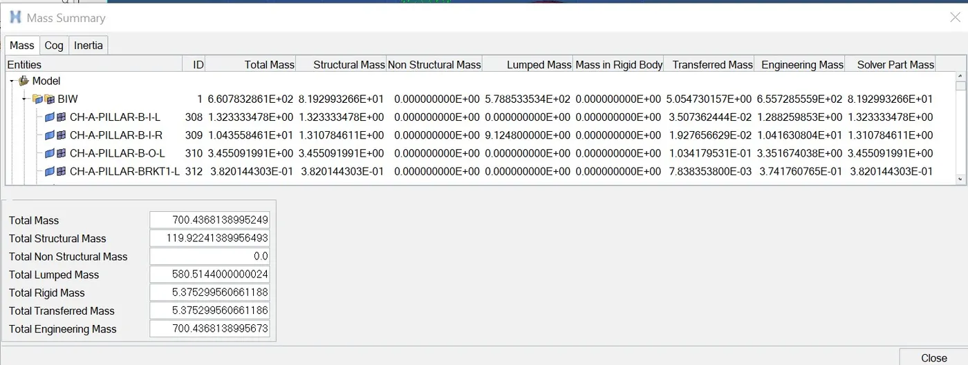
The targeted weight is given 700 kg where the actual mass before adding the external weight is 119kg.
To add the mass, click on added mass, and to create a new object select type0_mass is distributed to each node of the node group, and click save. check cog, simultaneously after giving the mass in the balance menu.
Run model checker
To check the model quality in Hypermesh. we will navigate to tools> model checker > Radiossblock. This will open a new window.
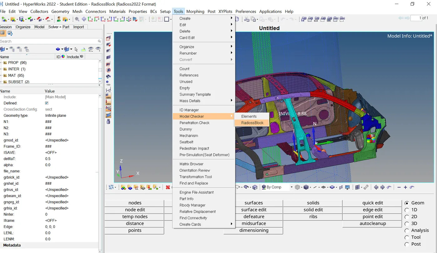
In this browser, we will click on Run checks command which is at the top right side in the above figure. After running the checks we get zero errors and warning we can fix the errors and ignore the warnings.
Run the simulation
- Click on the analysis panel in the Hypermesh.
- click on the radioss and save the model and run.

From the 0001.out file we can see the total number of cycles is 340733. The energy error is -2.3% which is the acceptable limit. The mass error is 0.1442e-7 which is also less than 5% which is acceptable.

Simulation in Hyperview
In the simulation of the vehicle-side crash, we can see the vehicle body is impacted on a pole. After the impact, the frame of the vehicle deforms and the vehicle body gets contracted around the pole with the left B-pillar. The cog of the vehicle is the same axis or direction of the pole. so we can see the deformation of the vehicle around the pole.
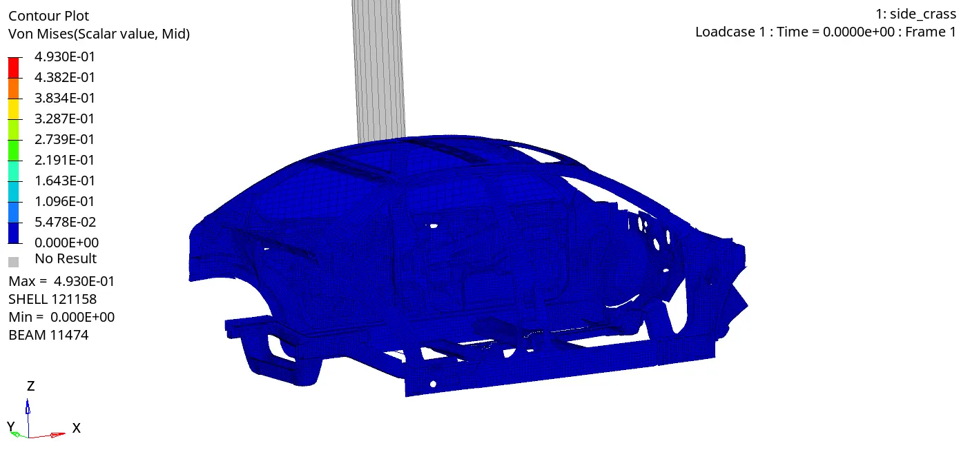
Stress is more in B-Piller and cross member as B-pillar takes the initial impact and then the impact is transformed to the cross member.
Plots in Hypergraph 2D:
Energies of the system:
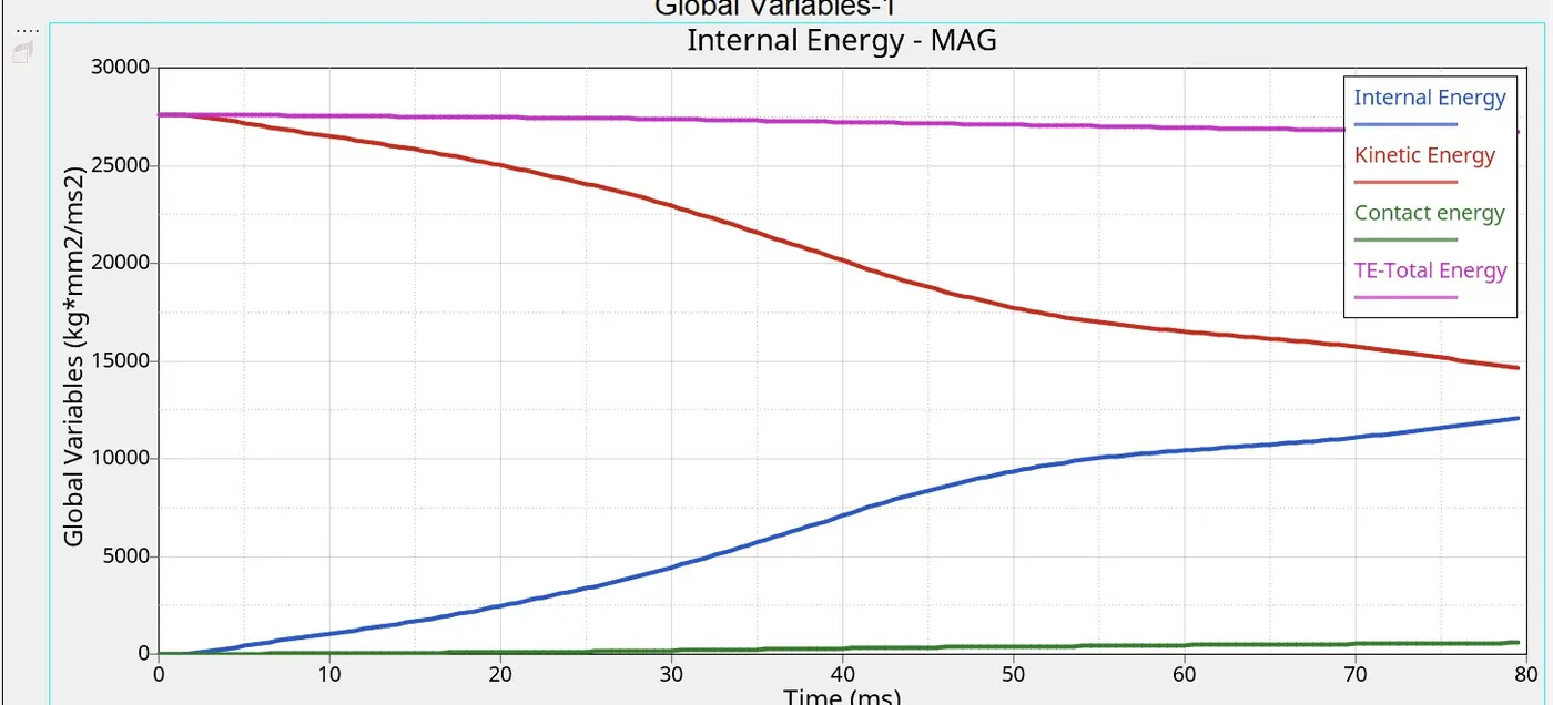
From the above plot, we can see there higher amount of kinetic energy at the start of the simulation but as the simulation progresses, the kinetic energy in the vehicle decreases and gets converted into internal energy, after that internal energy increases in the same proportion. Thus the total energy in the system is almost constant at 27500Kg*mm^2/ms^2 and due to some energy losses, we can see there is some decrease in total energy. we can see some amount of contact energy in the model as we have defined the value of friction in the type 7 interface due to which contact energy is generated.
Section force acting in the cross-member
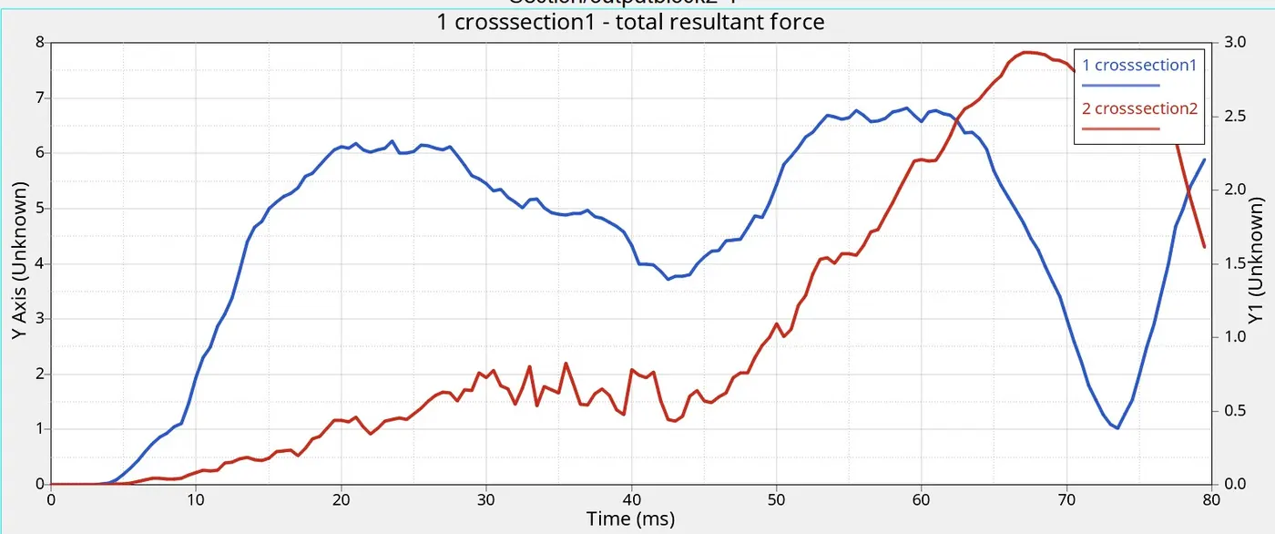
From the above plot, we can see the total result force in the real cross-member is more than the cross-member A. As the cross-member B is in line with the pole, it experiences more force.
Intrusions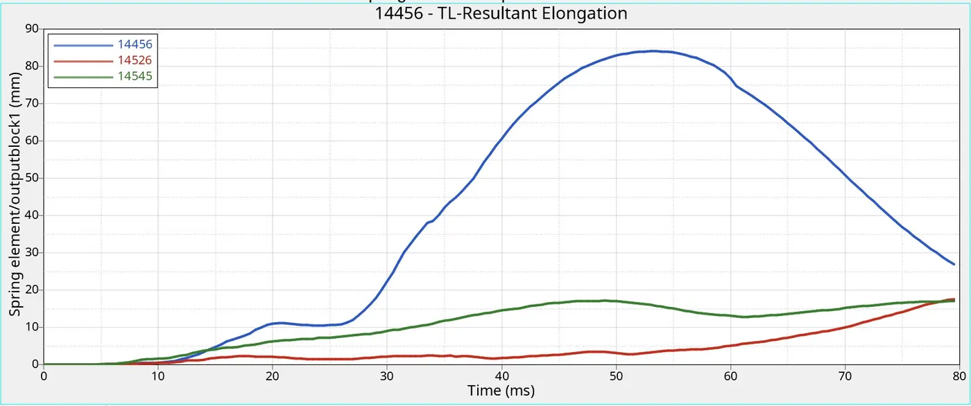
- Blue line-intrusion element at B-Piller-here intrusion is highest to the other element, it goes 85mm in 55ms and after that, its graph comes down.
- Red line- intrusion element at hinge piller-Intrusion at Hinge piller elongation is less as compared to others, here higher elongation is 17mm at 80ms.
- Green line- intrusion element at fuel tank -we can see through the graph the highest value of elongation is 16.5mm at 80ms.
Peak velocity of inner node door
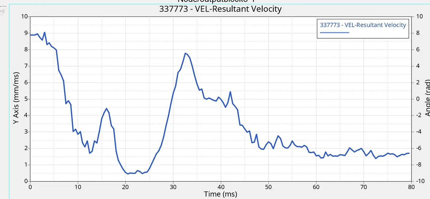
In this plot, we can see, how much the actual inner side of the door moves in the direction of the driver during the pole impact. The peak velocity measure at the inner door point is 9.10 mm/ms at 3ms. after, that the speed is starting to reduce to a great extent.
Conclusion
- we can see through the simulation of side crass and the results discussed. From the output file, the energy error and mass error are in an acceptable range so I can conclude that the simulation is pretty stable.