Assignment 7-Side Pole Crash Simulation Challenge
Objective: Performing Pole side-impact test on the given Automotive BIW using Euro NCAP standard.
FEA Model Given: The model consists of around 97 components, as shown below.
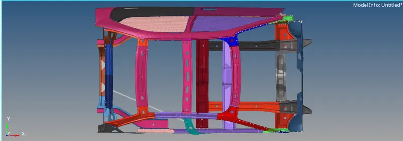
Euro NCAP standard is followed to perform pole side crash analysis:
https://cdn.euroncap.com/media/20874/oblique-pole-side-impact-test-protocol-v702.pdf
Procedure:
- Import the given 0000.RAD file into HyperCrash to visualize the COG of the given BIW.
Check Unit System:
- Once the file is open, it clearly shows the unit system (kg, mm, ms) in the BEGIN card of solver browser.
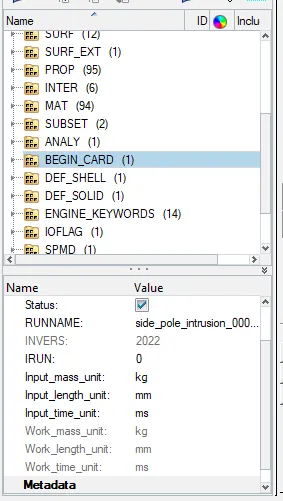
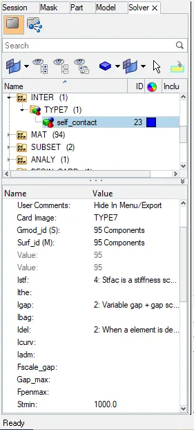
Create TYPE7 contact (Self contact): type 7 interface.
- Delete the existing contacts, and Create a new Type7 for all-body.
- Right-click in the Model tab and create contact TYPE 7. (by using INTER, self contact interface).
- Select all the elements except the front bumper element and enter appropriate values to define self contact.
- Select slave node and master element (All elements), set Istiff, Igap, Idel, Gapmin etc.
- Also, Iform=2(Stiffness).
Penetration check:
- Once contacted is created, check for the initial penetration and intersections of the node. (Tools>Penetration check)
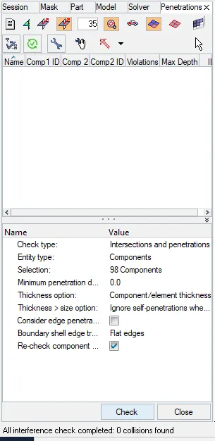
- Select the TYPE7 contact for penetration check, and it was found there is no penetration.
Create RWall.
- Open solver tab. (View>Browser>HyperMesh>Solver)
- Right-click on the solver tab and create the RWALL by scrolling the tab down..
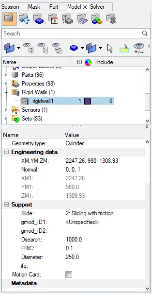
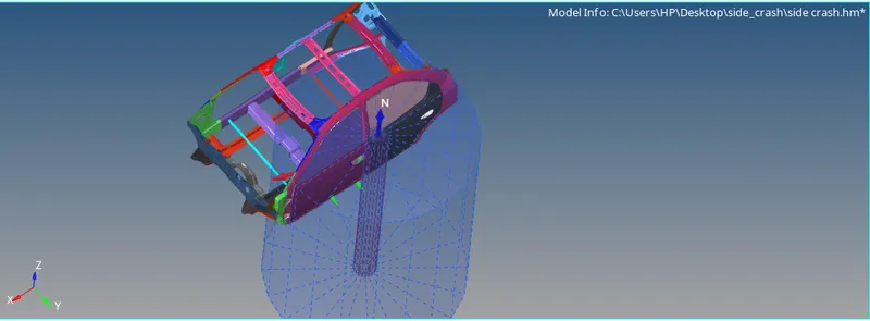
- Select the XM, YM, ZM to place the RWall origin (Tail) and enter the normal value by selecting the node (Head).normal allong to Z direction.
- Once done, change the Slide option to sliding with friction, and enter FRIC:0.1.
- Enter the Dsearch:1000mm.
Adding Mass:
- In order to add mass, open the browser tab and double click on added mass.(Admass)
- Create mass, depending on the nature of the load to be applied to the element.
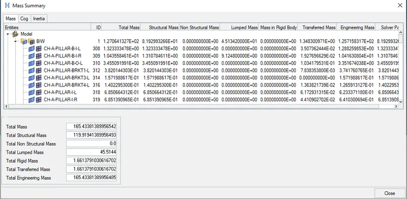
- check the mass details by using tools >mass details > mass, cog only.
right click on the solver deck create ADMAS card to add the mass to the model. by usiing Entity Ids select nodes where the mass to be added. 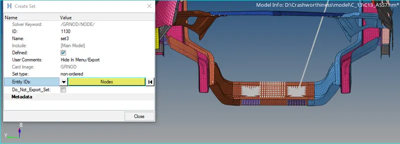
below mass details represent the full scale model i e 700 kg use tools > Mass details >mass, cog only.
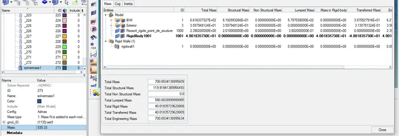
- With the help of added mass, the COG of the BIW was shifted close to the driver seating line.
- The total mass of the assembly finally came to around 700kg.
Apply initial velocity:
- Now apply the initial velocity to the whole BIW with 32kmph as shown below, resolve the velocity in X & Y Direction.
- To apply initial velocity (Solver>Right click>Boundry_Condition>INIVEL)
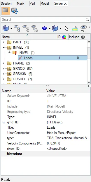
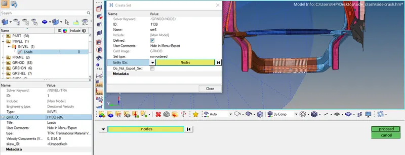
- Now create a node group set by right-clicking on grnd_ID, and selecting all nodes.
- Given RWALL is in +ve Y direction, enter the velocity as 8.94mm/ms, respectively.
CHECK MODEL CHECKER
Now check the model cheker by using tool >model checker>radioss.
if any errors and wornings will be occured during simulation we can eliminate before run the radioss simulatiion.
in the below image we can see there wasnt any error some warning might be allowed.
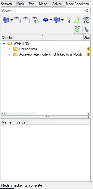
Now the model are ready to go to run radioss simulation due no penetration and no error.
Create Element time step and scaling:
- Create a time step for the node, and contact element as the standard value.
- Create the DT/INTER, Tscale to 0.9 & Tmin=0.0005. (Solver>Engine_keywords>DT>INTER)
- Create the DT/NODA, Tscale to 0.67 & Tmin=0.001. (Solver>Engine_keywords>DT>NODA)
Create frame (local coordinate system):
- To create the local coordinate system (Solver>Frame>moving). Since the BIW undergo deformation, coordinate needs to move along it.
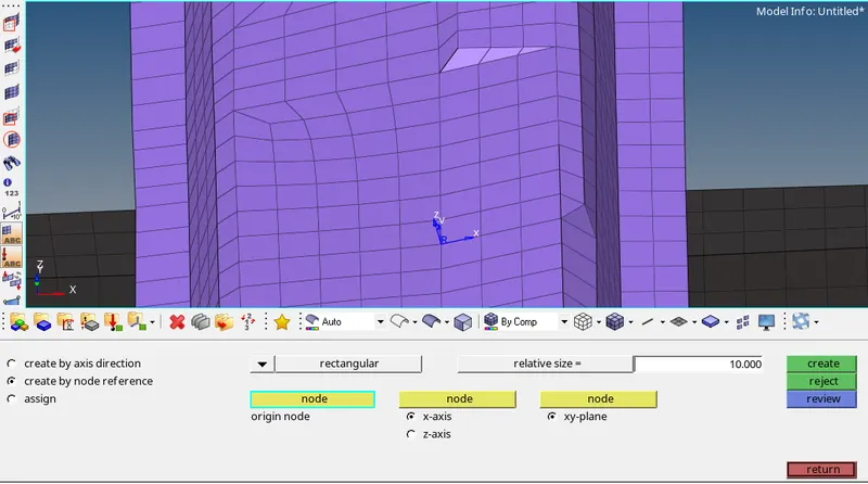
- Select the original node, then the 2nd node to define X-axis, and the 3rd node to represent XY-plane.
- Create a moving coordinate system across the roof, seat and B-pillar rocker reinforcement.
Create Section:
- Once the Moving frame is created, create sections at roof reinforcement B-Pillar reinforcement, and cabin seat reinforcement. (Solver>Right click>Sect>Sec
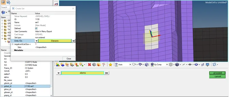
- Select N1, N2, and N3 to define the plane same as we select to create frame, and select Frame_ID according to the location created during the frame creation.
- Instead of selecting node group, select the element group manually. Right-click on grshell_ID and select (create and edit) the element on the section of interest and select element as shown in emage.
- Similar create sections for all the roof reinforcement B-Pillar reinforcement, and cabin seat reinforcement.
Output Block
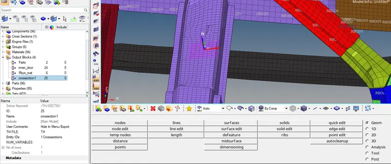
after create frame and section now we have to create output block for the same crossection.
assign Entity ID as crossection as we earlier created.
NUM_Variables is 1.
Create Spring Element:
- Create a spring element using node from side rocker to another-side side rocker. And apply property of negligible stiffness.
- Create two more springs to determine the impact on the passenger from the door and deformation of the B-pillar rocker.
- The purpose of the spring element is to determine the rate of deformation of elements between the two rockers, to understand the damage to the fuel tank and on the passenger.
INTRUSION AT B PILLER
creating spring we have to create first component by right click on component.
new component has tobe created to organsinse the spring into that collector when it has been created. rename the collector as spring at B piller.
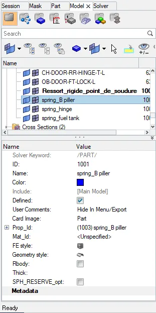
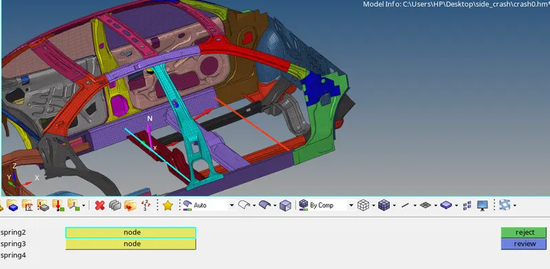
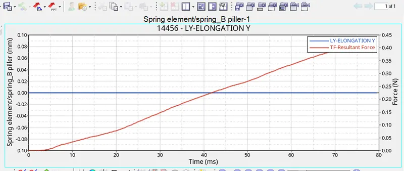
spring element can be created in 1D panel >springs>select the two nodes where we need measure the intrusion.
now create the 1D spring by at bottom of B piller as shown in below image.
Create a new property card for the B piller by using right click on browser.
right click property >create property rename as spring property for B piller.
assign card image as :P4 SPRING and assign mass.
assign the value 0.001 N/mm to the stiffness (K) and mass in the card.
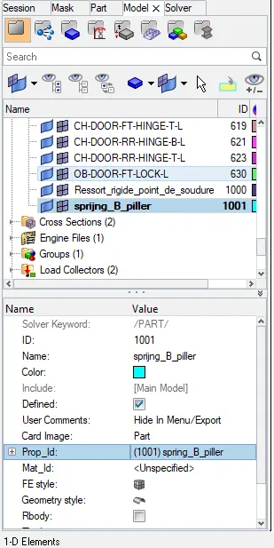
now, this property has to be assigned to the component thats been created earlier.
OUTPUT BLOCK
we have to create output block to the spring B Piller.
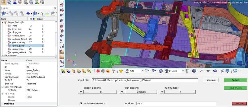
These have to be called into the output block. this can be done by creating a new output block, rename as spring B piller intrusion. changing the Entity IDs to element, and thereby selecting the spring that has been created.
CREATE SPRING AT HINGE
creating spring we have to create first component by right click on component.
new component has to be created to organsinse the spring into that collector when it has been created. rename the collector as spring Hinge.
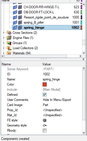
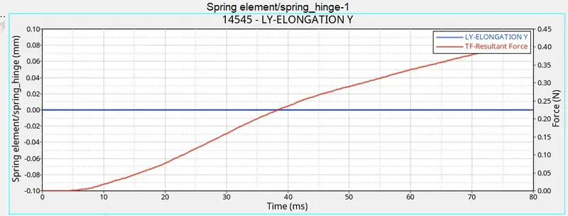
spring element can be created in 1D panel >springs>select the two nodes where we need measure the intrusion.
now create the 1D spring by at HINGE as shown in below image.
Create a new property card for the B piller by using right click on browser.
right click property >create property rename as spring property for B piller.
assign card image as :P4 SPRING and assign mass.
assign the value 0.001 N/mm to the stiffness (K) and mass in the card.
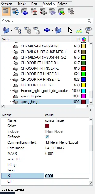
now, this property has to be assigned to the component thats been created earlier.
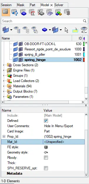
OUTPUT BLOCK.
These have to be called into the output block. this can be done by creating a new output block, rename as spring hinge intrusion. changing the Entity IDs to element, and thereby selecting the spring that has been created.
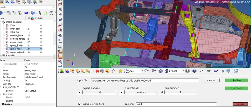
These have to be called into the output block. this can be done by creating a new output block, rename as spring Hinge intrusion. changing the Entity IDs to element, and thereby selecting the spring that has been created.
CREATE INTRUSION FOR FUEL TANK
creating spring we have to create first component by right click on component.
new component has to be created to organsinse the spring into that collector when it has been created. rename the collector as spring fuel tank.
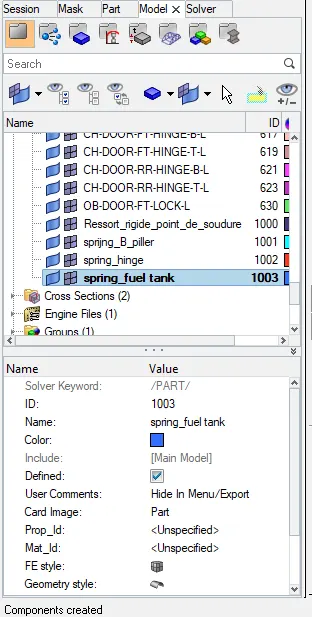
spring element can be created in 1D panel >springs>select the two nodes where we need measure the intrusion.
now create the 1D spring by at FUEL TANK as shown in below image.
Create a new property card for the B piller by using right click on browser.
right click property >create property rename as spring property for B piller.
assign card image as :P4 SPRING and assign mass.
assign the value 0.001 N/mm to the stiffness (K) and mass in the card.
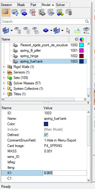
now, this property has to be assigned to the component thats been created earlier.
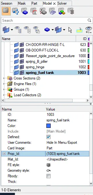
OUTPUT BLOCK.
These have to be called into the output block. this can be done by creating a new output block, rename as spring Fuel tank intrusion. changing the Entity IDs to element, and thereby selecting the spring that has been created.
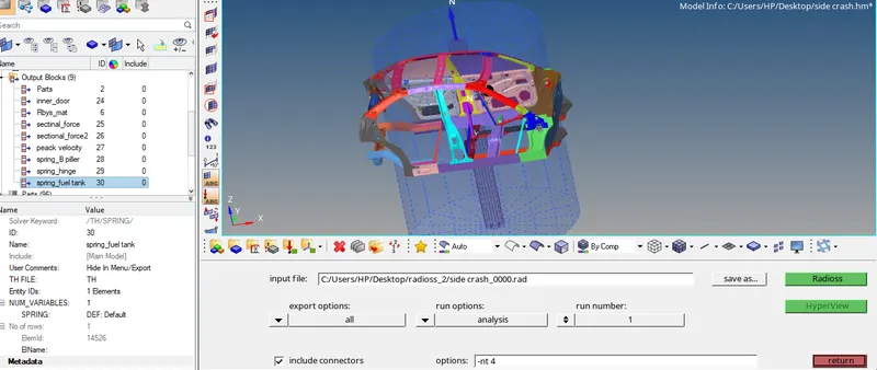
These have to be called into the output block. this can be done by creating a new output block, rename as spring Fuel tank intrusion. changing the Entity IDs to element, and thereby selecting the spring that has been created.
Create Time History(TH):
- Create a Time History file for all the critical points where data need to be extracted, such as
- Type7 connectors
- von Mises stress in element
- Reaction on RWall
- Force at section
- Displacement of spring elements
- The velocity of the passenger inner door panel.
Result:
von-Mises Stress (25ms):
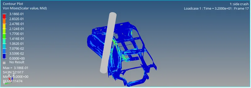
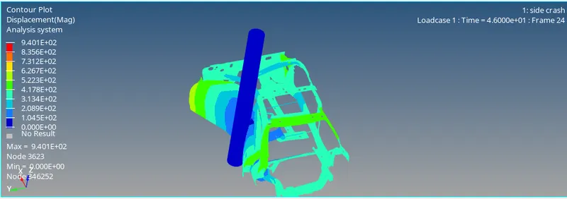
Displacement (25ms):
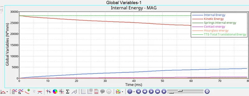
Energy Graph:
Spring Deformation B-pillar :
Spring Deformation Hinge:
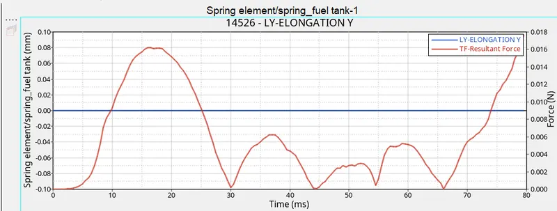
Spring Deformation Fuel tank :
Reaction force by rigid side-pole:
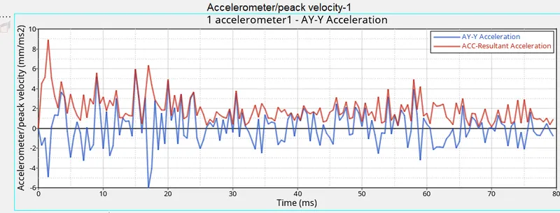
The Peak velocity of the inner panel:
Result Validation:
Analytical Solution:
- Total kinetic energy is maximum at t=0, which can be determined analytically using the kinetic energy formula.
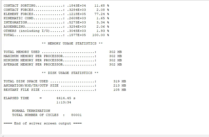
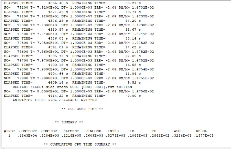
Approximately we got the same error in energy through simulation, i.e around -2.0 %.
Conclusion:
- Mass distribution in the automobile plays an important role during crash analysis, COG must be kept as low as possible to ground and close to the centre of the car.
- Lower COG provides great stability to structure even at very high speed and reduces the possibility of role over during the crash.
- Less the mass, less the impact energy generated. Providing reinforcement steel on the car door and providing side airbags, can increase the impact time resulting in less impact on passengers.
- Try to increase the time taken for the intersection of internal energy and kinetic energy curve, resulting in less impact on passengers.
- Using more ductile material with moderate strain hardening material also absorbed more impact energy by undergoing large deformation on seat and roof rail reinforcement.
- During the crash, it was observed that the cage undergoes large deformation, due to the absence of the other component of the automobile.
- It is required to provide more reinforcement near the fuel tank.