Assignment 7-Side Pole Crash Simulation Challenge
Checking the unit system
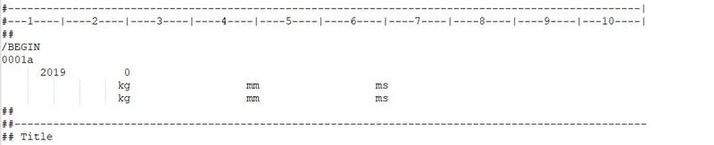
The units of the model can be checked from the begin card or the 0.rad file in model
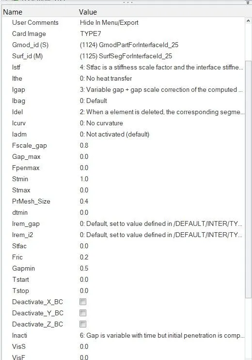
Creating an interface with appropriate properties
The given interface consists of many interfaces which are not found to be necessary for running the model, a new type 7 contact is created with friction 0.2,inacti 6,igap 3, fscale 0.8,prmesh 0.4,idel 2,friction formulation 0, stiffness formulation 2 and a minimum stiffness of 1.
Checking for penetrations and intersections
The penetration check can be performed by selecting and running the penetration check option from the tools option and there are no penetrations found .
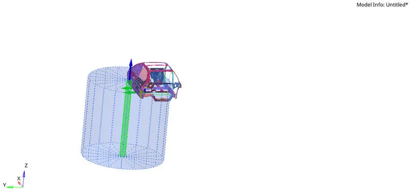
Creating a rigid wall with a friction of 0.1 :
By using the create option and slecting the cylinder option from the rigidwalls section.A set of three nodes have to be selected tht define the normal for the crossection of the cylinder. At the end we specify the data for the support section and a friction value to complete the creation of the cylindrical rigid wall.
Balancing the mass and centre of gravity :
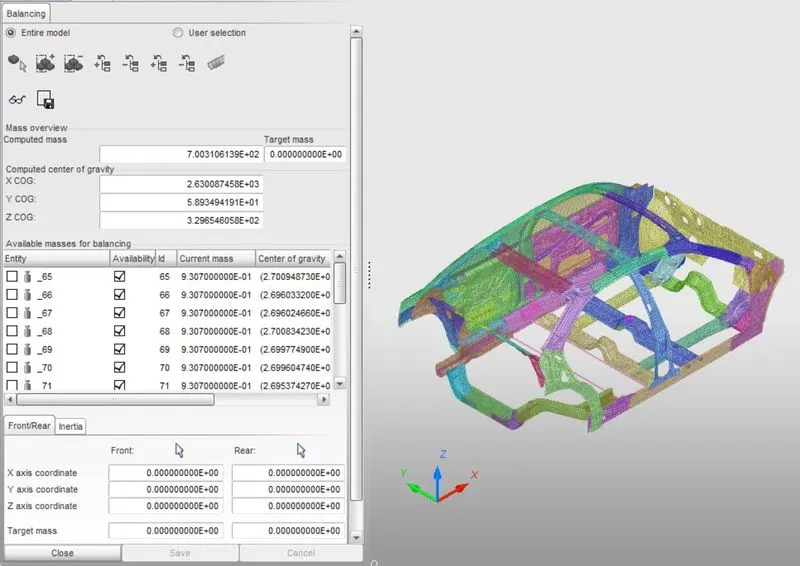
Mass balancing and centre of gravity position optimization can be performed using hypercrash.The original model has a weight of 119 kg, and to make it 700kg we can add a total weight of 581 kg to the already existing model.Mass is added at appropriate locations at the hinge pillar to balance the cg.
Assigning a initial velocity of 20 mph to the model :
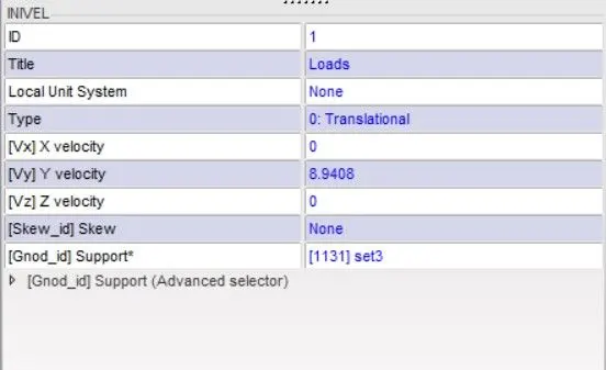
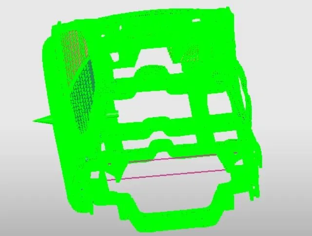
To assign a initial velocity to the model, we need to create a load collector and apply the type inivel collector.In the edit section of the load collector we can add the velocity of 20mph which is 8.9mm/ms in our unit system.
Using model checker to verify the quality :
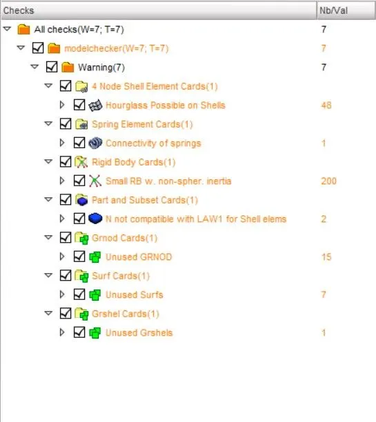
The so far created model is verified with the model checker that is available in the quality section of hypercrash and no errors have been detected by the checker.
Assigning a minimum time step :
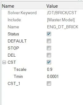
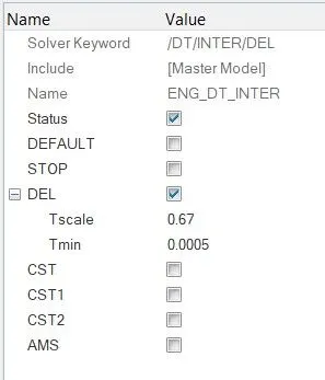
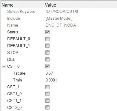
The time step can be edited by selecting the DT option from the engine keywords in the solver section.
As per the given values the minimum values are given as 0.0001,0.0005,0.0001 for nodal,elemental and brick time steps.
Output requests:
SECTIONS
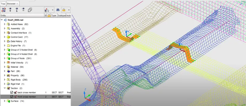
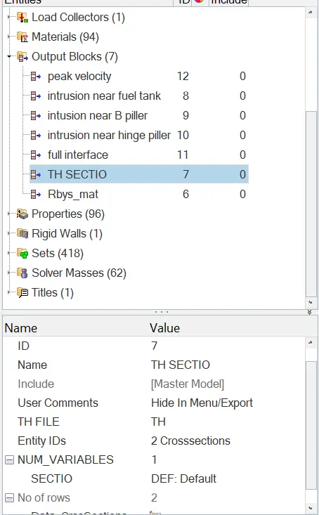
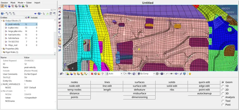
To obtain the sectional forces at the cross members we need to create crossections.This could be done by creating a crossection using the 3 node option at bothe crossections which are in close proximity to the cylindrical rigid wall. And create the a request in the TH section for both the crossections.
INTRUSION
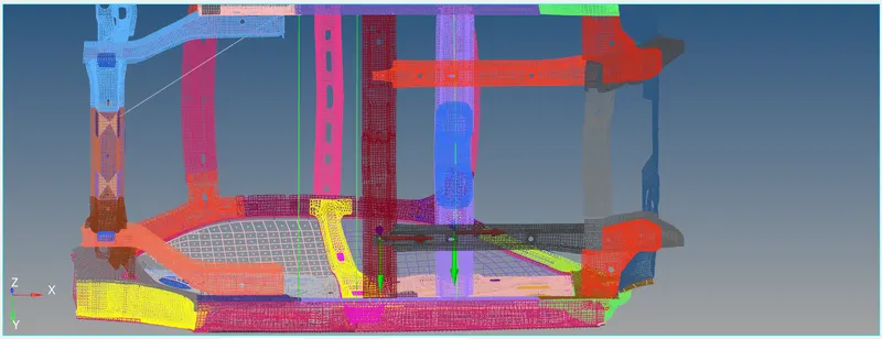
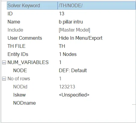
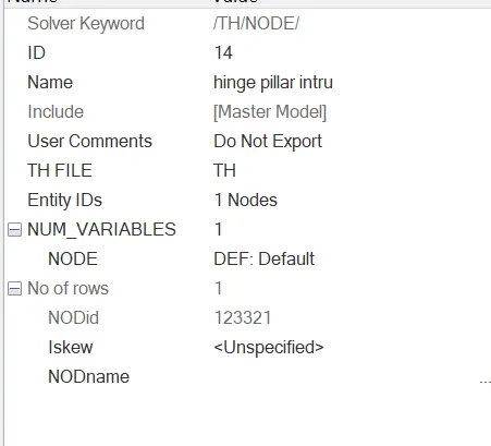
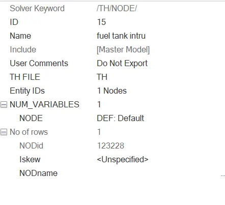
To obtain the deformations of the B-pillar, hinge pillar and at the fuel tank region, we can create springs with minimal stiffness and mass so that they do not interfere with model's dynamics. At the end of this create a request in the TH section of the solver and select the respective nodes on the side which they are prone to deformation.
PEAK VELOCITY
Create another request in the Th node section and select the node that is on the front left side door which is going to crash into the rigid wall. By doing this we can get the peak velocity.
Output:
After completing the analysis in radioss, open the out file to see the energy and mass error
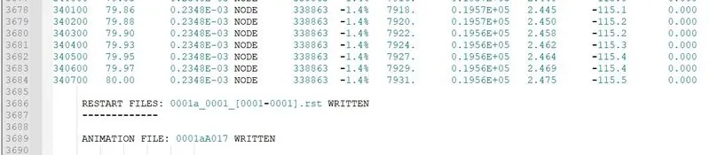
Here the energy error is -1.4% and mass error is 0 which is acceptable then we move onto next step.
Then open HyperView and run the h3d file and review displacement and von mises stresses induced in the BIW structure.
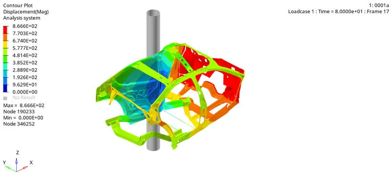
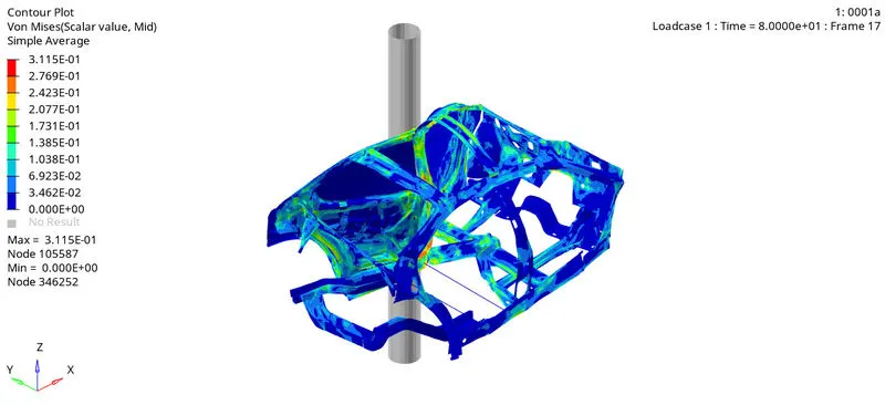
From above picture we can see that the maximum stress induced in the BIW structure is 0.3N/mm2
Then we open the hypergraph to view the graphs related to energies and forces.
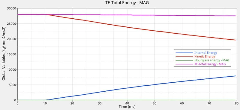
As we can see kinetic energy gradually decreases and internal energy will increase as it absorbs the surrounding energy (Deformation).
Hourglass energy is very minimal as we have given QEPH formulation. so the elemental stifness is maintained to minimise the hourglass energy and deformation.
Total energy is almost constant but due to some energy loss in energy error there is a slight decrease in total energy.
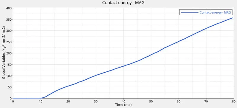
We can see the contact energy keep rising as the collison keep progressing.
Sectional Forces:
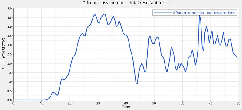
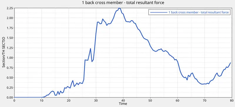
After 10 milliseconds the BIW comes into contact with rigid pole resulting to total resultant force getting generated.
We can see a maximum force of 4.7KN is obsorved in the front cross-member. Then the curves falls down and we can again see a spike in the curve as the collison continueously, as a result of of torsional forces. hence the resultant force had a spike. The front cross member is more firmly built than the backcross member. hence we cant see much of a deformation in the section.
We can see a maximum force of 2.25KN in the back cross member. Since the back cross member is not firmly built we can see lot of deformation for very less force
Peak velocity:
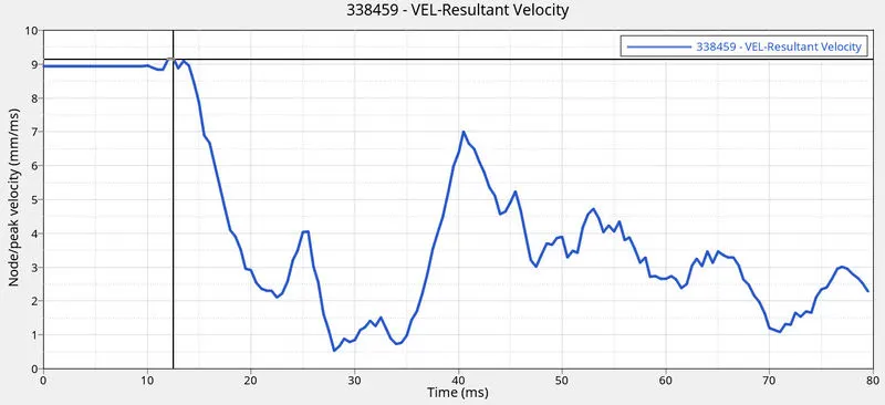
We can see The peak velocity of the selected node is 9.08ms at the very beggining of the crash, around 12ms and it slowly decreases but had a rise again due to deformation of the door at 40ms and then slowly falls. the velocity has a irregular ups and down because due to the piller being in the middle, when the crash happens, in the middle of the crash some components of the vehicle starts to go under torsional force this increases the forces and velocities.
Intrusions:
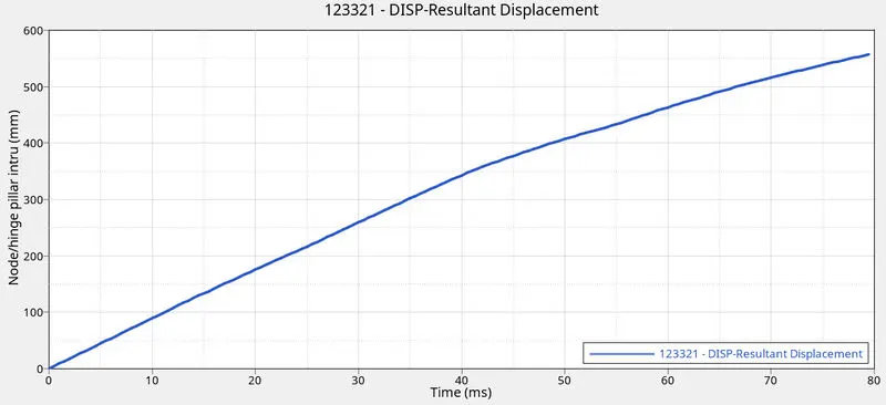
Above graph gives the intrusion in hinge pillar.
The intrusion is found to be 5.571e+02mm
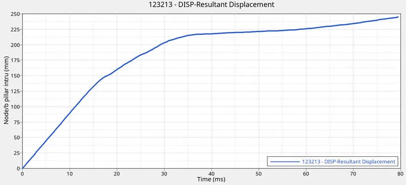
Above graph gives intrusion in b-pillar
The max intrusion is found to be 2.448e+02mm
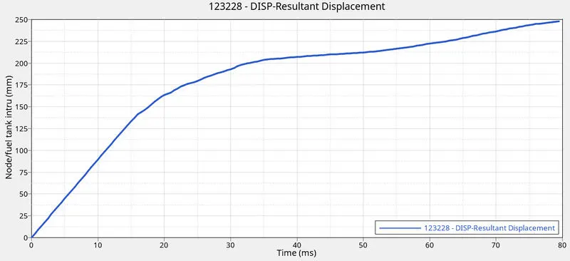
Above give intrusion in fuel tank.
The max intrusion is found to be 2.481e+02mm.
CONCLUSION
From this project we have learned:
- How to apply a cylindrical rigid for side crash applications
- How to apply multiple intrusion points
- how to find the velocities in particular areas
- Applying sections and gathering data in particular part