Assignment 3-2D Element Formulation Challenge
Base Simulation of improved shell element
- First change the run time to 55ms in engine file.
- Then as we know,
Tfrequency = Time of sound travel/ No. of animation steps
Given animation steps to be 25 so frequency is
55/25 = 2.2(update in engine file)
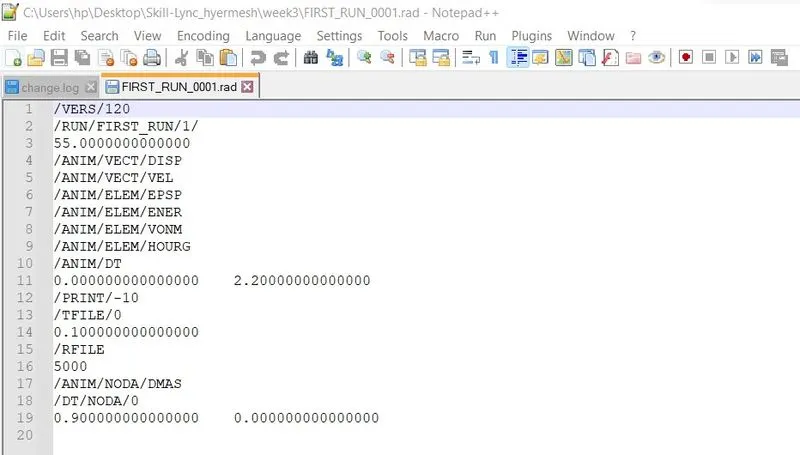
Case-1: Run File without applying properties
- After saving the engine file import the engine file in the hypermesh and run the analysis with radioss
- In the result files generated open 0001.out with text editor and observe the energy and mass error at end of the computation.
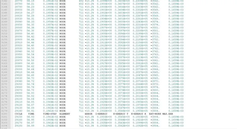
- Ideally the energy error should be of at most in between -15% to +5%, but the closer to 0% the better. Next, we should look into simulation result.
- From above we can see that the energy error at the end of the computation is -10.3% which is within the range and mass error is 0.1659E-03, so we can proceed forward.
- Now open the h3d file in HyperView.
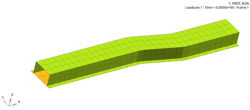
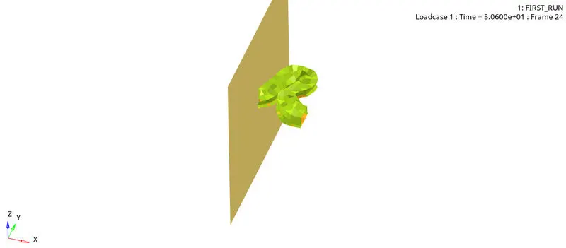
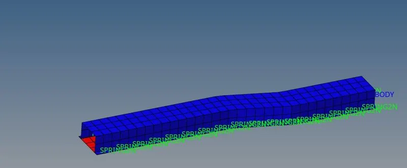
- So as per the model, there is a rigid wall on front of crash can and rigid body created at other end of the crash can where mass is applied. So due to initial velocities at the rigid body the crash can is getting pushed into rigid wall. Due to resistance deformation takes place. Now if we look into the time plot from t01 file in hypergraph 2d
Energy graph
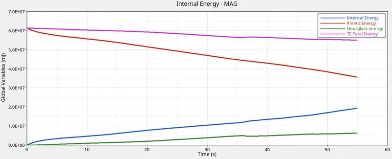
- Here Kinetic, Internal, Hourglass and total energy are plotted
- Kinetic energy starts at huge value as we have initial velocity and huge mass and internal energy starts at zero as there is no deformation at zero seconds.
- From above we can see max total energy of 6.1E+07 and min total energy is 5.4E+07. So, we can see that total energy will keep on decreasing up to 55 milliseconds.
- We can also observe hourglass energy which should not be there.
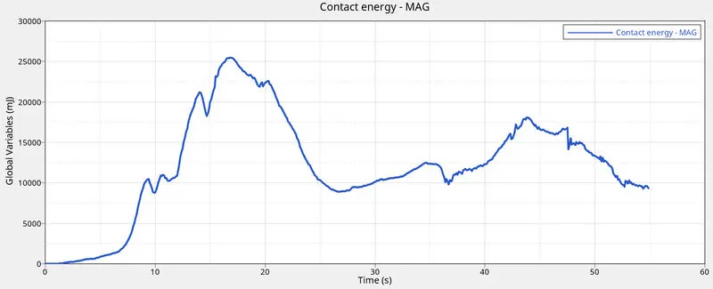
- We also see contact energy plot to check whether there is any negative contact energy which may be caused by undetected penetrations which may be due to use of coarse meshes.
Rigid wall forces
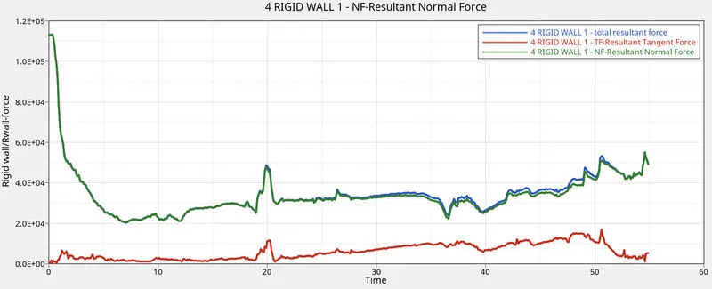
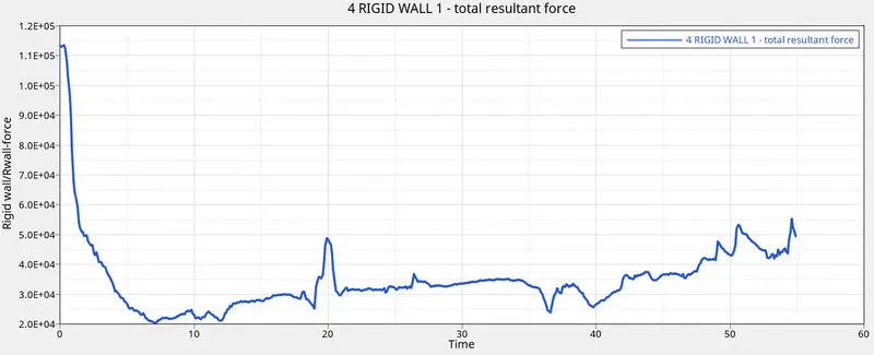
- Above Normal force, frictional force and total resultant force is plotted.
- Here we can see the normal forces that were applied on the rigid wall by opposing component.
- When the first impact between rigid wall and crash can happened there was huge force and as it progressed due to internal deformation of crash can the force started decreasing. From above we can see that the resultant force is almost matching with the normal force.
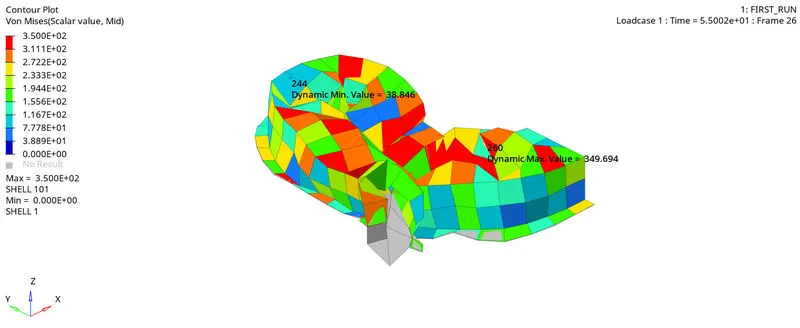
Von mises stress
Case-2: Run after applying properties to crash can.
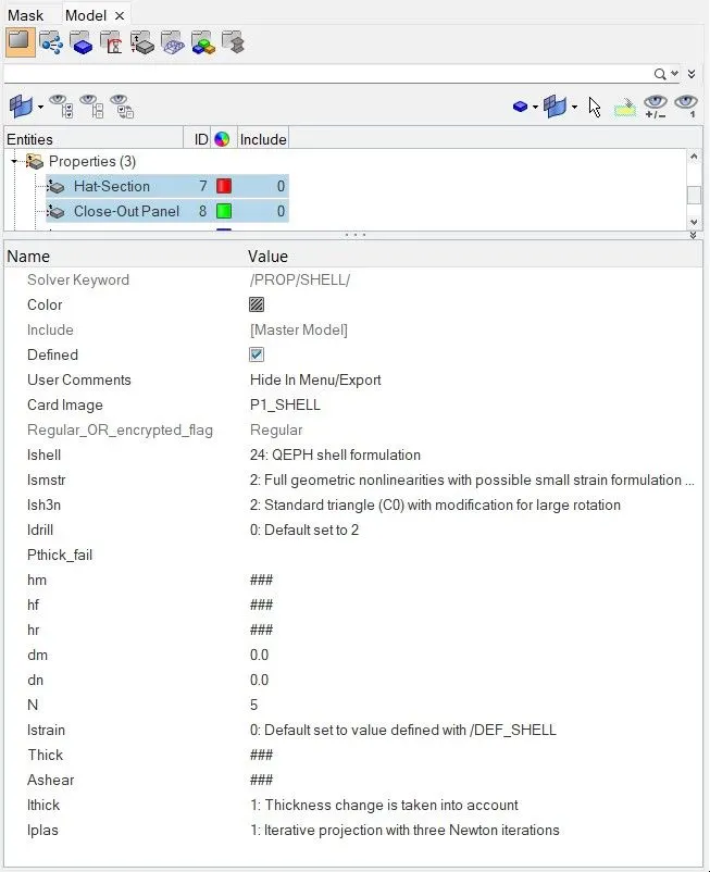
After changing all the shell element properties to recommended properties, save and run the simulation.
The properties which should be uploaded are as follow
Ishell =24 QEPH 4 nodes shells are best combination of cost and accuracy.
Ismstr=2
Full geometric nonlinearities (default) with possible small strain formulation activation in RADIOSS Engine.
Ish3n=2
Standard 3 noded shell (CO) with modification for large rotation(default)
N=5
Number of integration points set to 5 for accuracy bending.
Ithick=1
Thickness change is taken into account for accuracy.
Iplas=1
Iterative plasticity for good accuracy.
Now save the file and run-in analysis radioss and we observe energy error and mass error from engine file
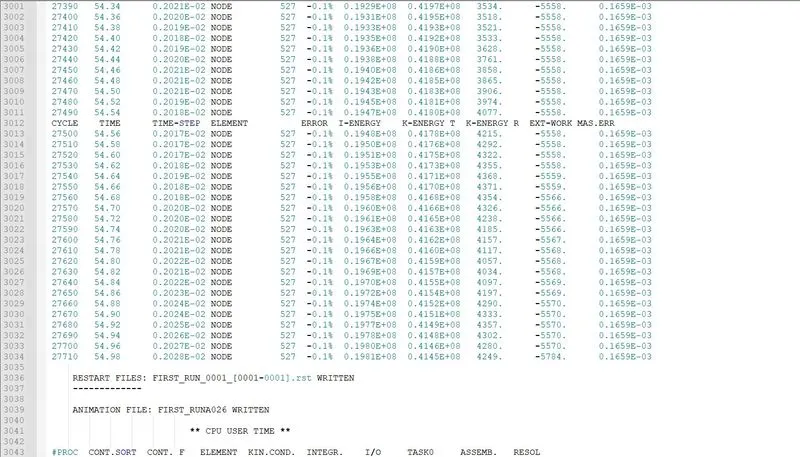
The energy error is reduced from 10.3% to 0.1% at the end of the computation which is close to 0% and is acceptable. Mass error is 0.1659E-03, which is same for both cases and independent of changing element properties.
Now open the h3d file in Hyperview.
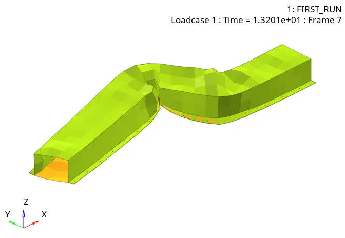
Open the hypergraph2d and choose T01 file to plot the graphs.
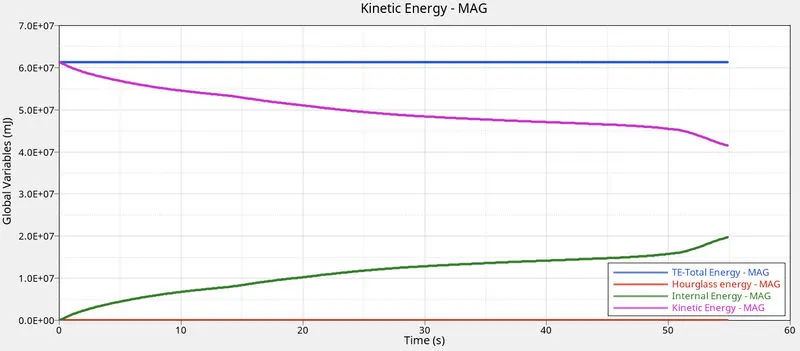
Energies graph
- Now from below we can observe that there is no hourglass energy after applying the recommended properties.
- We can also observe some changes in kinetic energy, internal energy and total energy.
- since KE is 1/2 mv^2, it depends on the mass. in the first case due to the hourglass effect some of the nodes are neglected, but after using QEPH formulation the neglected nodes are also consider and hence the decrease in the KE is less compared to the first case
- Save the template of both hyperview and hypergraph2D.
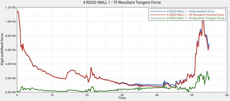
Rigid Wall Forces
- From above we are able to observe that, Frictional force which is represented by resultant tangential force value increase slightly with time.
- from 50ms we can see there is a huge spike in the resultant normal force and total resultant force, this is because the QEPH formulation prevents the hourglass
- in the first case due to formation of hourglass which is a formation of extreme deformation of the elemnts and nods, due to this there are no stresses produced and as a result zero energy aborbed
- but now since we can counter the hourglass effect with the QEPH formulation the stress and energies in the elements at the extreme deformation area are noted and hence the spike in the curve
- Whereas we can see that normal force and resultant force appear to be similar from above graph. since there is no velocity to the rigid body, the resuktant force and the normal force tend be similar
Von Mises stress
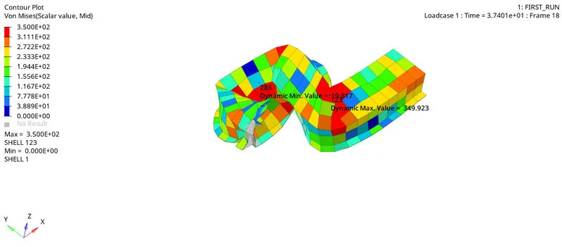
There is no much change in the von mises stress as the strain remains same, since we are not changing the material properties of the elements.