Assignment 7-Side Pole Crash Simulation Challenge
AIM:- To perform the Side Pole crash analysis on the BIW part of the car using the hypermesh and Solving with the Radioss and to check where the stresses are acting on it.
OBJECTIVES:-
- Check unit system and either follow [Mg mm s] or [Kg mm ms].
- Create an appropriate interface, friction 0.2, and recommended parameters.
- Make sure of no penetration and intersections.
- Create a rigid wall with friction 0.1 as per the reference model.
- Compare the model weight with the reference model and use added masses to reach the target weight of 700kg while getting CG about the required range.
- Initial velocity - 20mph, as per the standards.
- Check the model using model checker
- Give Timestep value as 0.5 to 0.1 microseconds.
- Give rn time to 80ms.
OUTPUT REQUESTS:-
- Sectional force in the cross member.
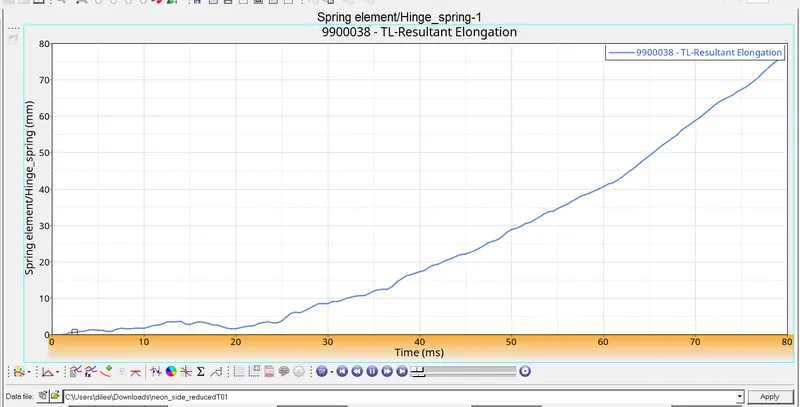
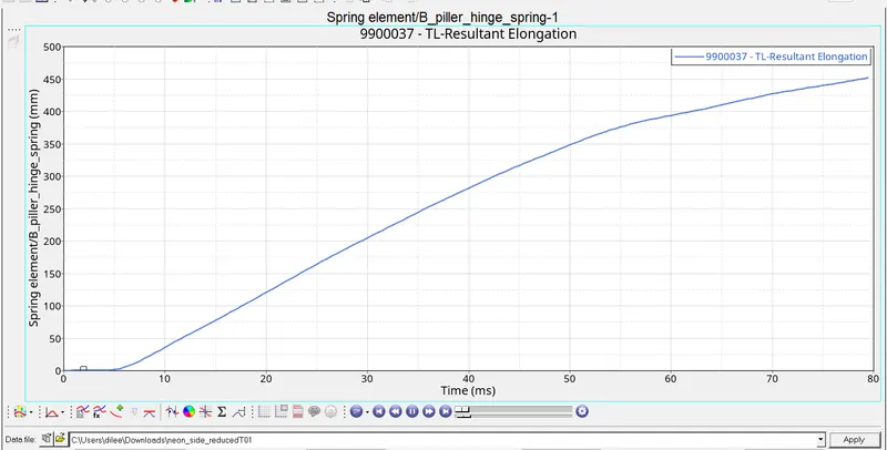
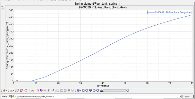
- Intrusion at B pillar,hinge pillar and fuel tank region. Provide recommendations on what can help to reduce Fuel tank intrusion.
- Peak velocity of an inner node of the door.
PROCEDURE:-
- First we have to open the 0000.rad file in the text editor or notepad to check the unit system used in the file.
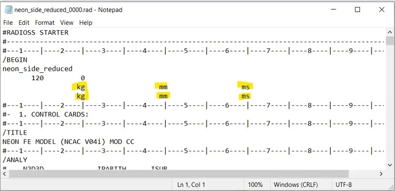
- The unit system used is kg-mm-ms, the recommended unit system for the analysis.
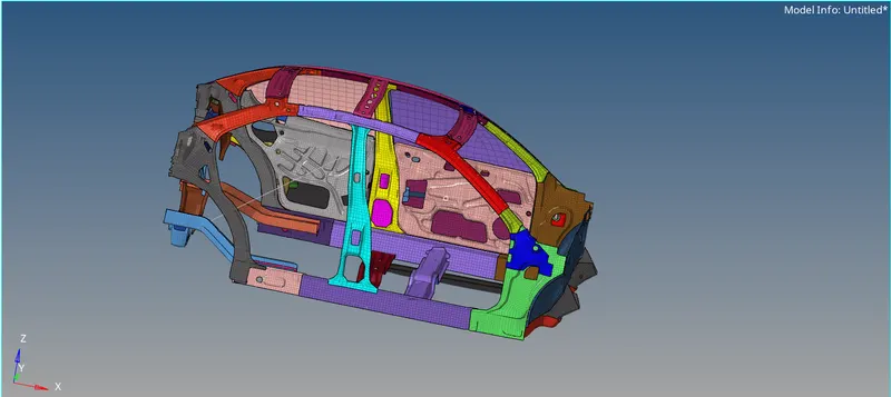
- Firstly, we have to import the model file into the HyperWorks as a slover deck
- we can import the file by >>import>>import slover deck>>choose the 0000.rad file and then import the file.
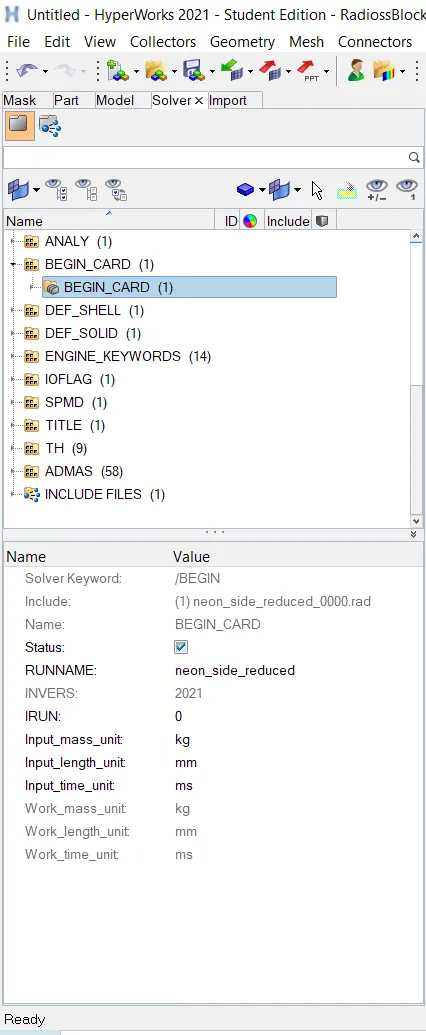
- We can check the unit system of the imported file by begin card. >>Model>>cards>>begin_card
- Once the unit system is checked, Now we have to create a proper interface with recommended properties and friction =0.2
- We can create the interface of the file by >>view>>hypermesh>>slover>>right click and create the type 7 interface
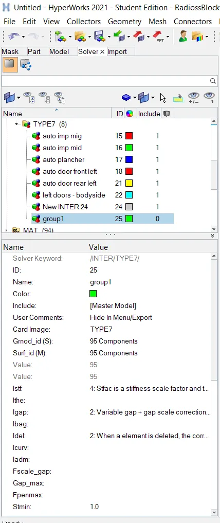
Type 7 interface is created with recommended properties
- For smooth simulation of the model, there should not be any penetrations and interfaces. In order to check the penetrations, we have to follow >>Tools>>penetration check>>select group>>check
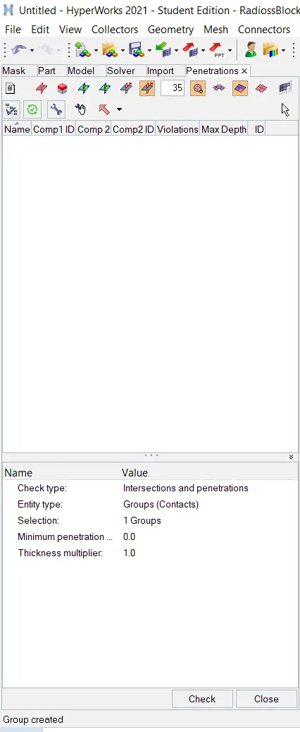
Penetration Check
- There are zero penetrations and interfaces were found in the model.
- Now we have to create a rigid wall with the friction of 0.1 between the car and the rigid wall.
- For this, >>slover>>click right click>>create>>RWALL>>CYS
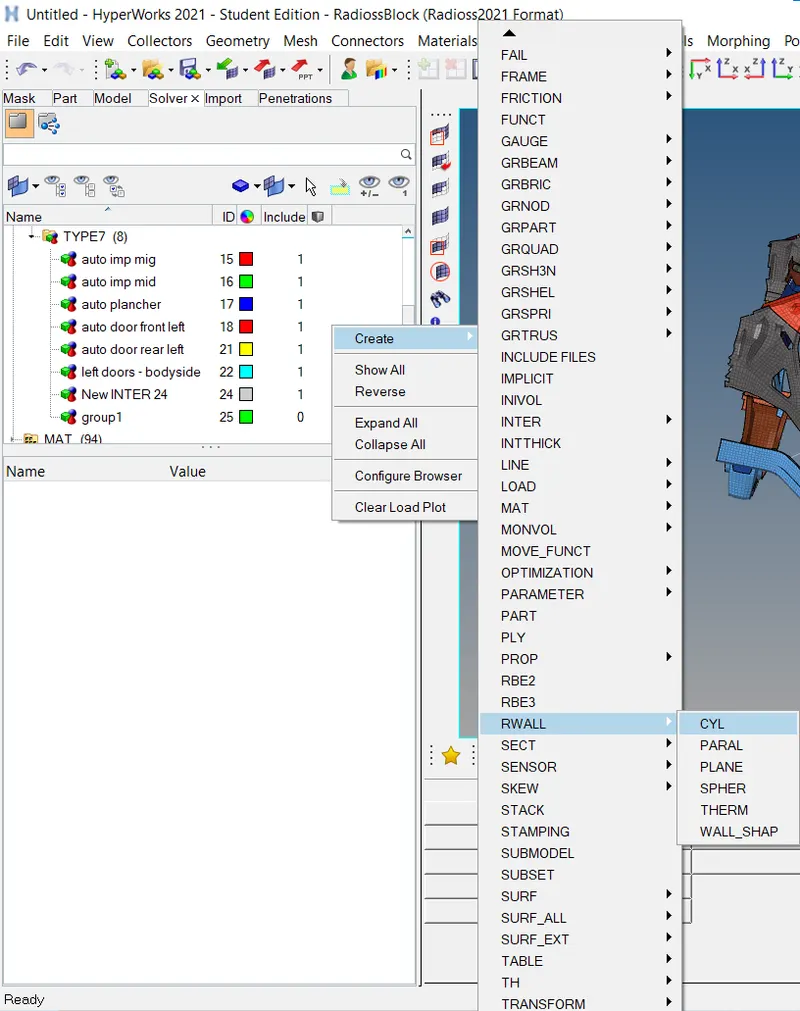
User interface of RWALL card
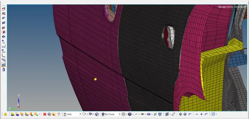
- To make a rigid pole, we have to create a reference node. First, we will create a temporary node in the middle of the bumper. after that, we will translate that node to create a gap between the pole and the car as shown in the image to maintain the offset.
- Enter the friction value as 0.1 and Dsearch as 1000 and create a rigid wall
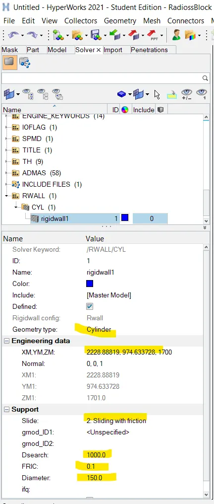
Creating the rigid pole
- Now we have to Compare the model weight with the full-scale 300k nodes model and use added masses to reach the target weight of 700kg while getting CG about the required range.
- For this, >>Tools>>mass details >>mass COG and inertia.
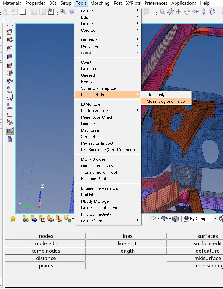
Interface for mass checking
- Therefore, in this model, we have a total mass of the value approximately equal to 188.02 kg as shown in the below figure. But in the given 300k nodes full model we have a target mass of 700 kg.
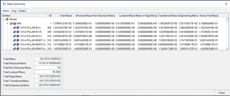
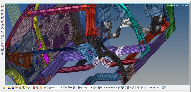
- Therefore, in order to create the mass. First, we have to select the nodes by creating GRNOD. In order to create the masses on the nodes, we have to create GRNOD by >>Slover>>create>>GRNOD>>nodes and select the nodes
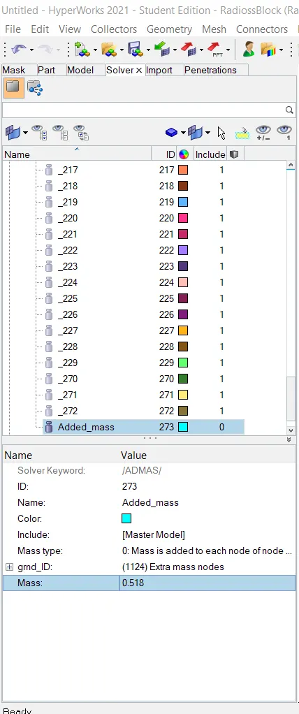
- Now we have to add masses to increase the overall weight of the car by assigning GRNOD ID by >>Slover >>Create>>ADMAS.
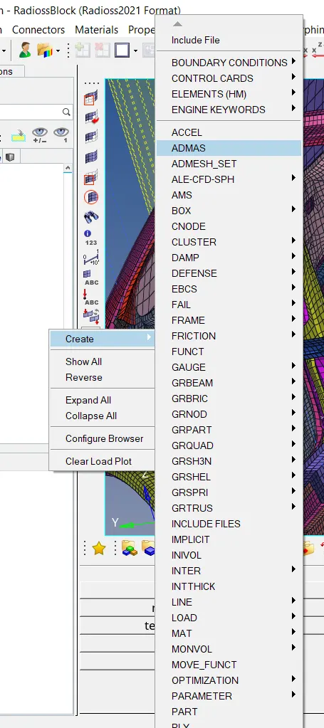
- Now in the add mass card, we have to give the GRNOD ID and the respective target mass.
- Now, we have to check the mass card again to check the target mass and CoG
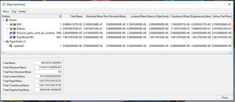
- The target mass is achieved very nearly with negligible error.
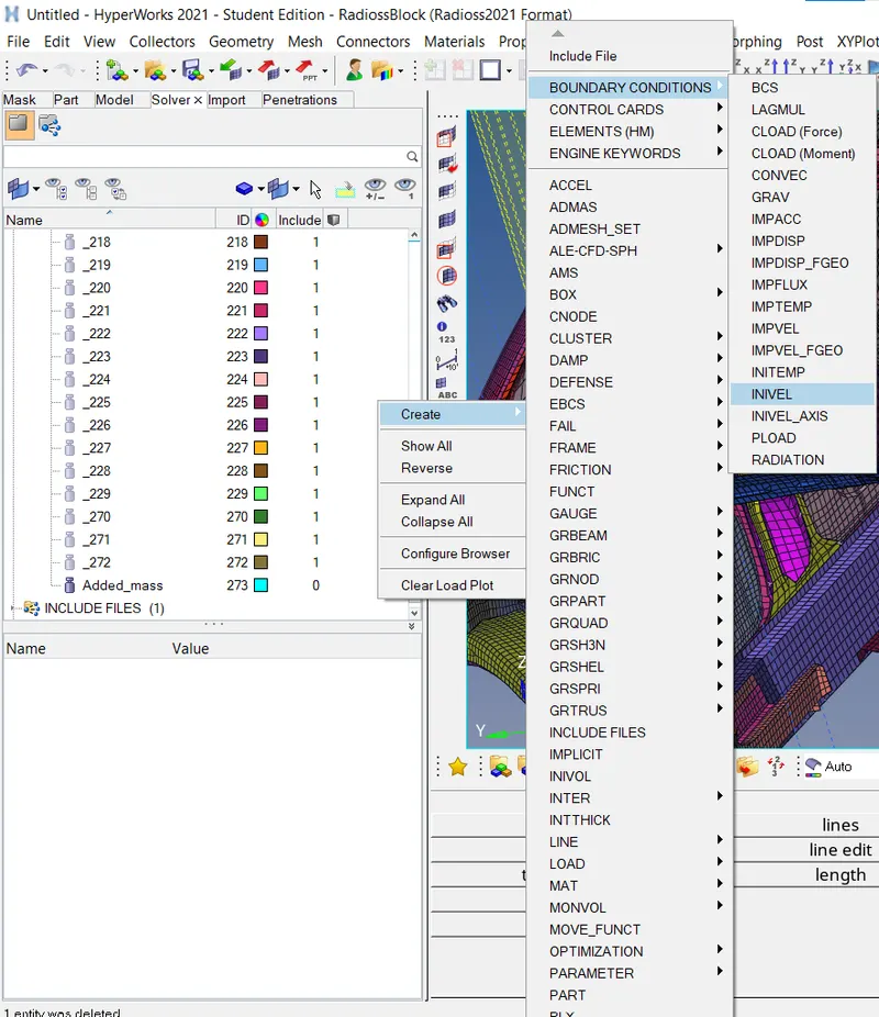
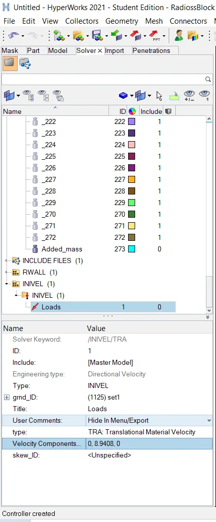
- Now we have to create an initial velocity of 20mph for the model.
- For creating the initial velocity we have to follow >> slover>>create>>boundary conditions>>INIVEL
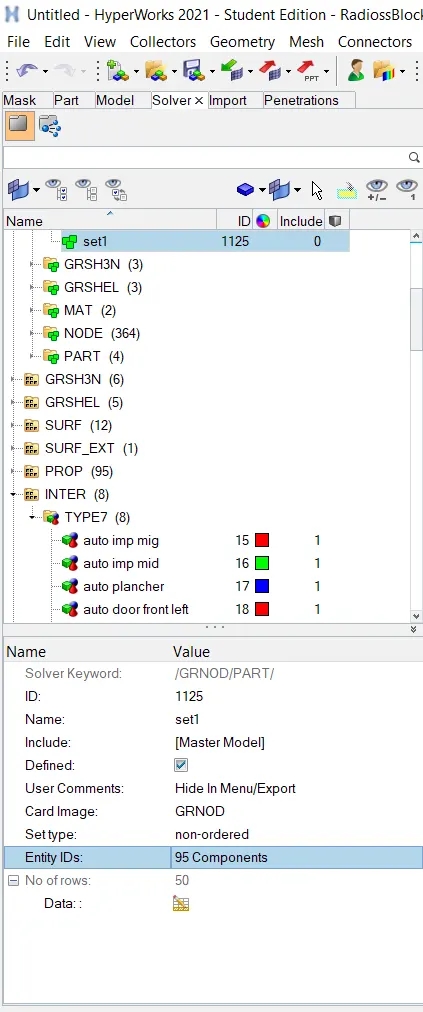
- Now we have to create the GRNOD id by selecting all components as entity id as discussed in the above step.
- And we have to provide the initial velocity as 20 mph (8.9408 mm/ms) in the INIVEL card in translational Y-direction and the remaining two directions will be constrained.
- Now we have to check the quality for smooth simulation
- First I will import the model into the hypercrash application then I will move to hypermesh for further simulation
- we can open hypercrash >>Applications>>hypercrash>>select appropriate unit system >>run
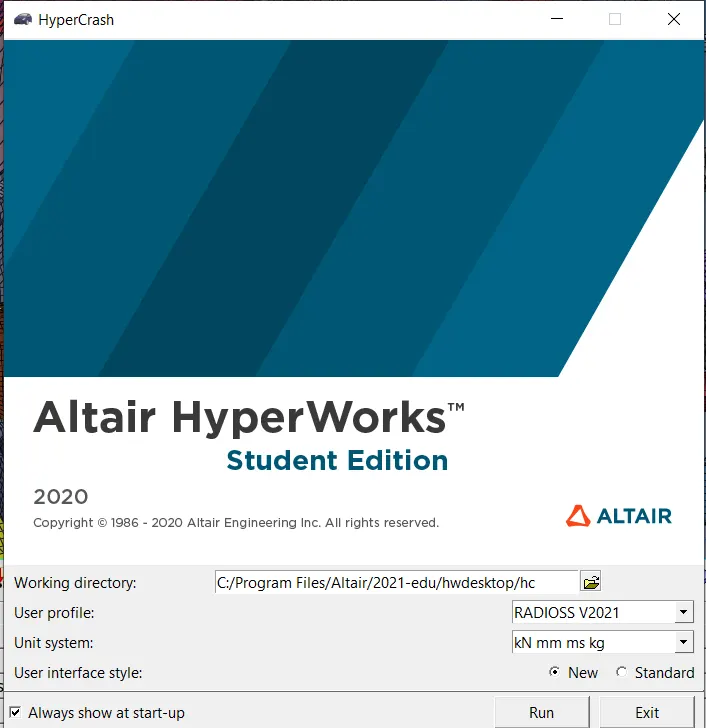
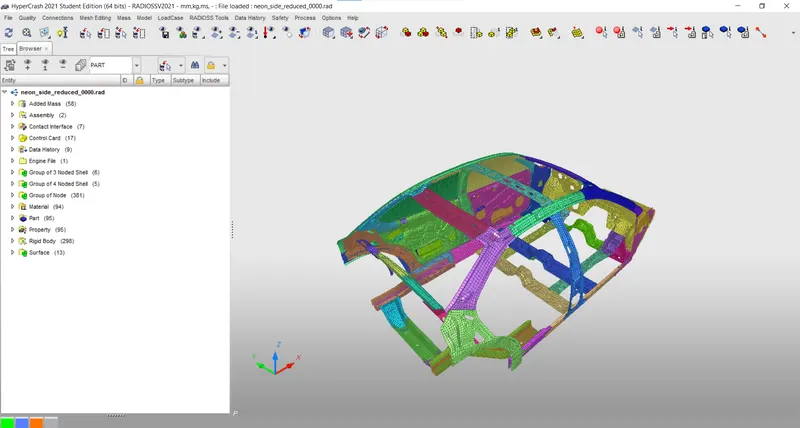
- We will use hypercrash to run the model checker. In order to switch the model from HyperWorks to the hypercrash
- we can import the file by >>File>>import>>RADIOSS>>choose file path, then import
- We can check the quality of the model by >>Quality>>model checker>>Run
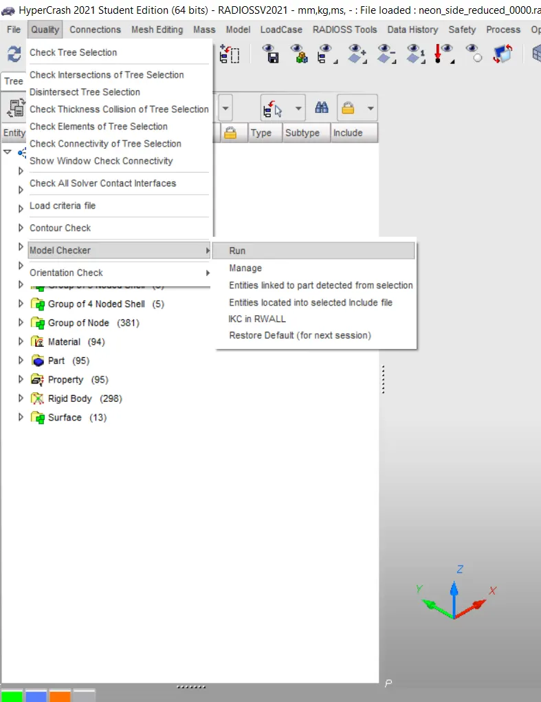
- After clicking the Run we will get the report as shown below
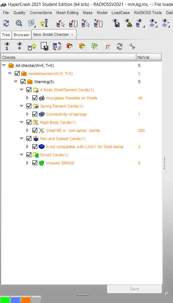
- Now we have to apply the Time-step value of 0.5 to 0.1 microseconds.
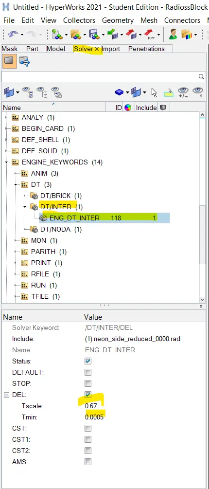
- we have different methods to create time steps such as INTER, NODA, BRICK, etc and we have a different time step control such as CST, CST1, DEL, etc.
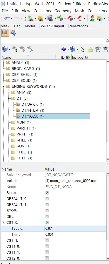
- In this case, we have created INTER and NODA as time step control.
(I) ENG_DT_INTER
- This method is used to create a time step control
- we have to keep 0.67 as the time scale factor and the time step control as 0.0005.
- We can change the values as shown below
(II) ENG_DT_NODA
- this method is used to control the time step from the nodes.
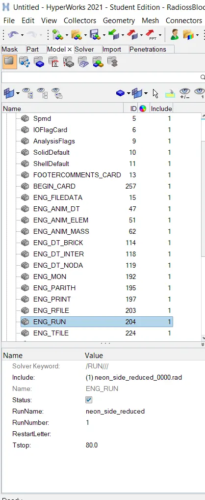
- Now we have to give a run time of 80 ms
OUTPUT REQUESTS
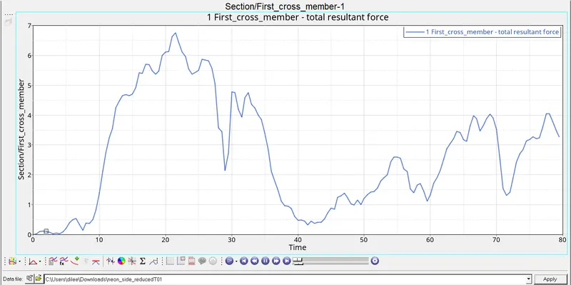
(I) Sectional force in the Cross member
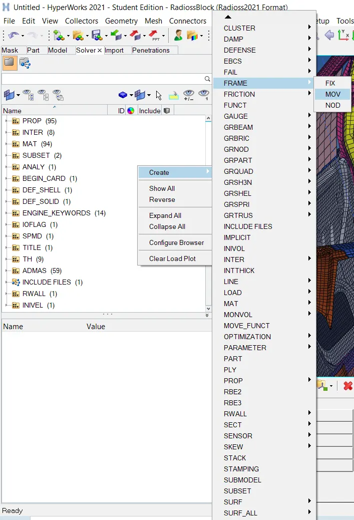
- In order to create a SECTION, first we need To create FRAME card on particular node of the taht section, which called as local axis system. In this Moving frame is attached with the nodes which is selected as origin.
- In order to create frame card we have to follow the order as shown in the below figure.
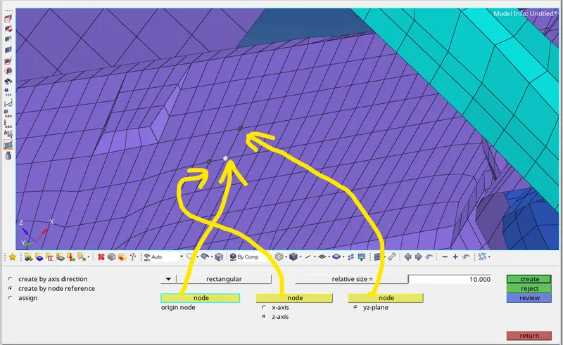
- In order to assign the parameters in the FRAME CARD, we have to define origin node and then define z-axis with second node which is in the direction of crash and Third node for plane as shown below
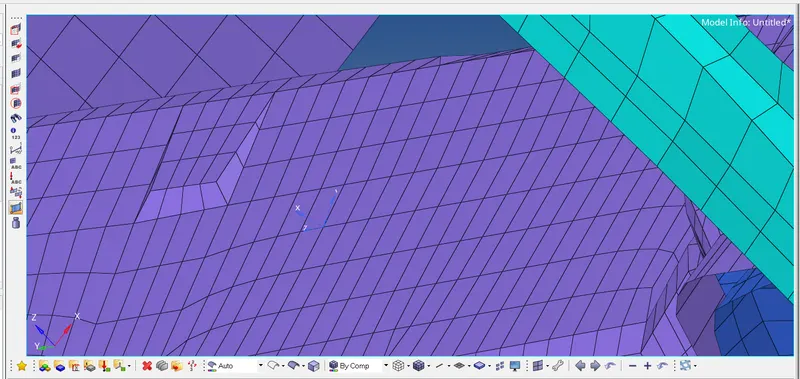
- Once axis is created at node it looks like this
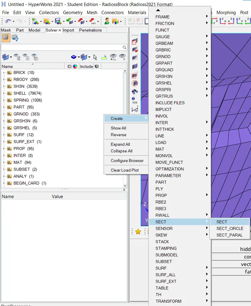
- Now we have to create sectional force on the cross member . The sectional force can be created as shown in below figure
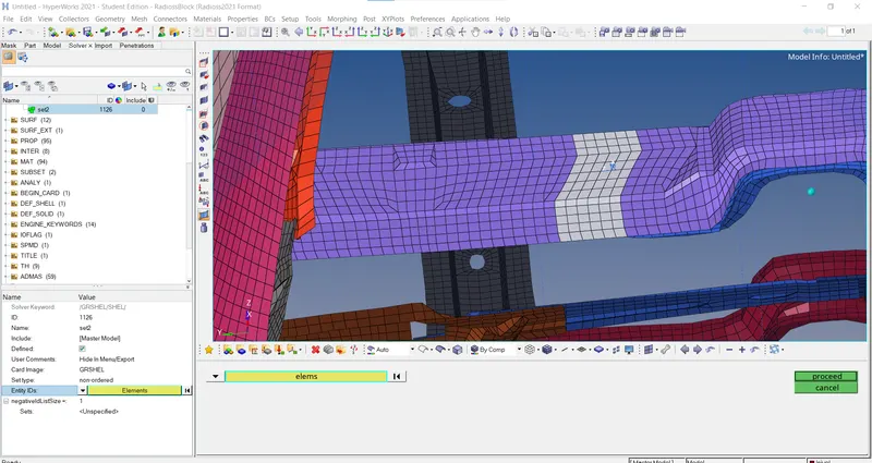
- Now we have to crete GRSHEL card by selecting elements as shown
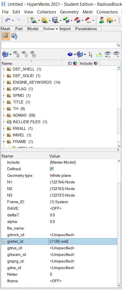
- Now we have to assign GRSHELL id in SECT parameters as shown below
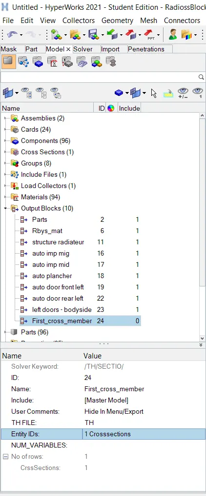
- Now we have to give output block requests in the model browser as shown in the image
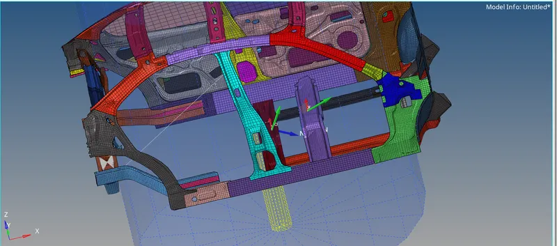
- Similar steps to be performed to create sectional forces on second member. Once completed the above steps the system looks like as shown in the below figure
(II) Intrusion at B pillar,hinge pillar and fuel tank region. Provide recommendations on what can help to reduce Fuel tank intrusion.
- Spring elements are created to understand the intrusion which means how forces are coming inside the car cabin.
- In order to create intrusion spring, First we have to ccrete a component id as shown in the figure.
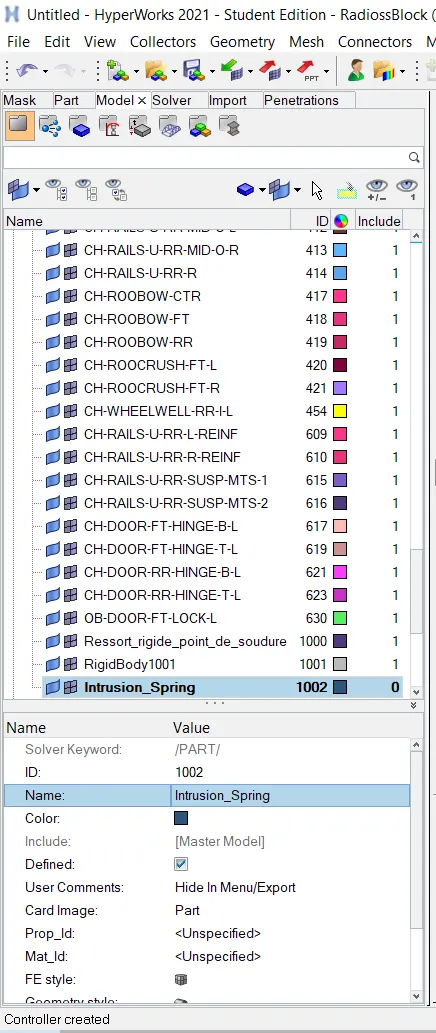
- In order to create spring we have to follow >>1D>>Springs

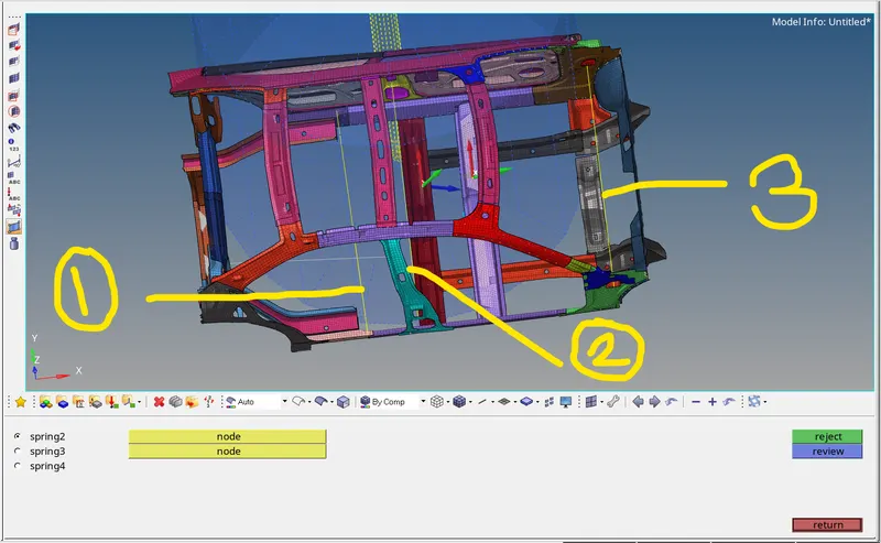
- In the figure 1indictes Fuel tank region, 2 indicates B-piller region, and 3 indicates Hinge region.
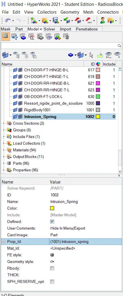
- Once the springs are created, Now we have to give proper id for the created springs as shown below.
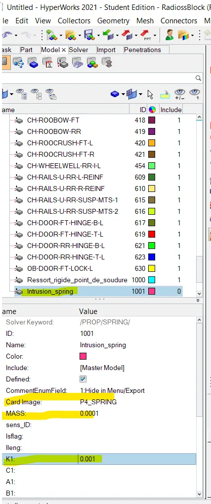
- Now we can assign spring property id card as shown in the figure
- Now we have create the time history for the created springs as shown below.
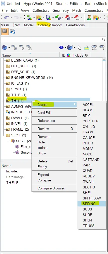
- Once time histroty for all the springs is created as shown below
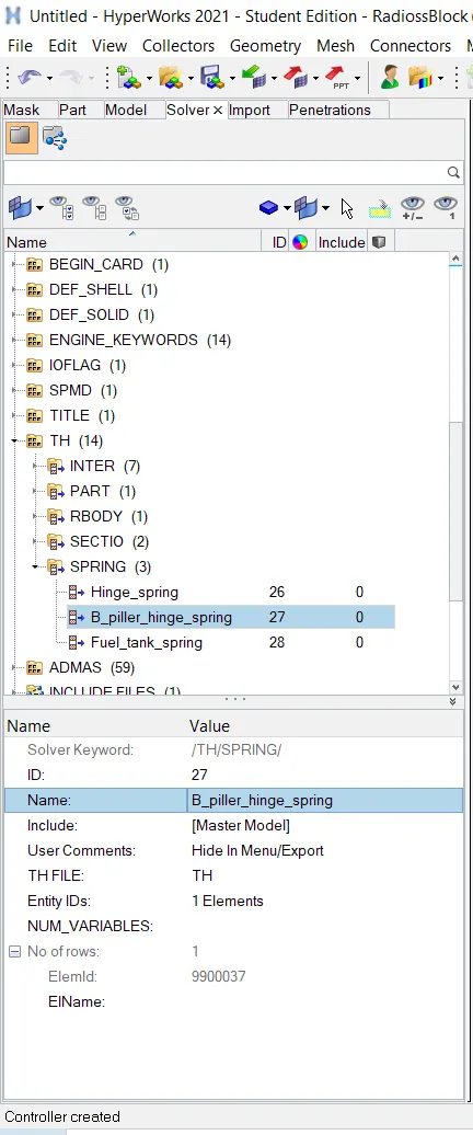
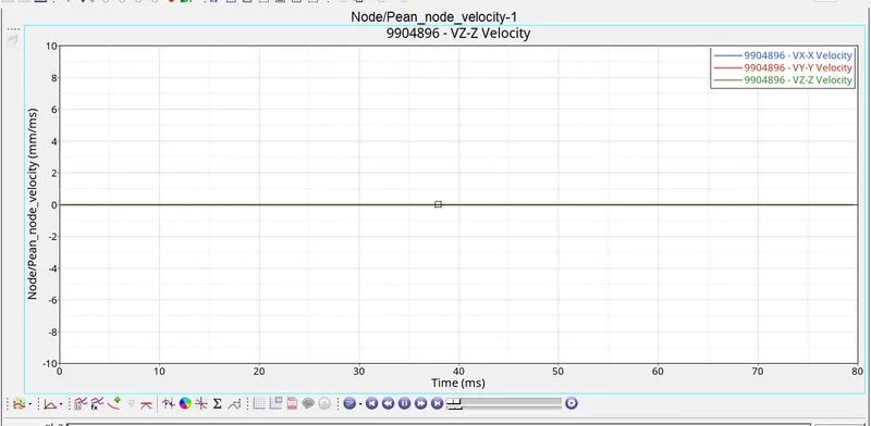
(III) Peak velocity of an inner node of the door.
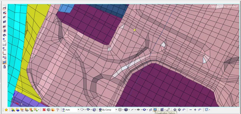
- In order to calculate the peak velocity of the inner door, first we have to create a temporary node on the inner door of the car as shown in the figure
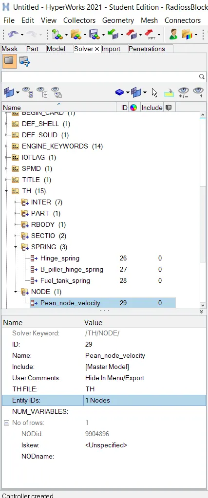
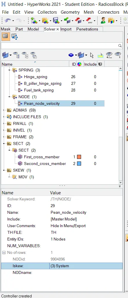
- Now we will create a Time history of the node as shown in the figure
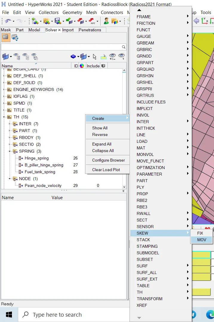
- Now we have to create a moving skew frame at the selected node as shown in the figure
SIMULATION OF SIDE POLE CRASH ANALYSIS
- we can run the simulation >>analysis>>radioss
- we have to save the in the new folder to store all output files. In the options tab, we have to recommend keeping "-nt4" which indicates 4 crores to run the simulation faster. where "nt" indicates a number of threads.

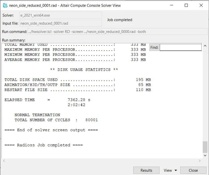
- After clicking Radioss, the analysis window pops up and we can see after a few minutes the job was done successfully
- The simulation is done, now we have to visualize it in hyper view. for this we have to open hyper view and import the .h3d file.
- and opening contour, then select von misses and averaging method as a simple average method.
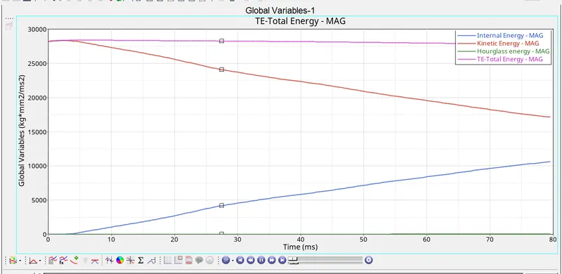
- In the next step, we have to carry out the energy and mass error analysis. For this, we have to 0001.out file in the notepad. Scrolling to the end we can see the energy error and mass error
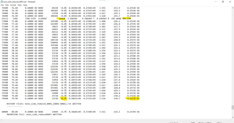
- The final energy is -0.7%, which is very acceptable, and the mass error is 0.2572E-01
- Now we have to plot the graphs in the hypergraph tool and in hypergraph we have to import the.T01 file.
CONCLUSIONS:
- Simulation was done successfully on the given BIW model as per the given conditions.
- All the output requests have be calculated and plotted such as sectional forces, at B pillar,hinge pillar and fuel tank region. Provide recommendations on what can help to reduce Fuel tank intrusion.