Assignment 2-RADIOSS Engine File Editing & 3D Meshing Challenge
#AIM:- To perform RADIOSS Engine file editing and create a 3D meshing surface for the given components.
#OBJECTIVES:-
- We have to answer all the given questions
- We have to create a 3D meshing tetra and hex mesh with target tet size = 5 mm, hex size= 10 mm, and tet collapse=0.15 by maintaining the quality.
#QUESTIONS:-
-
Check the material properties of the rail component and calculate the speed of sound in steel rail=_______
-
The length of the rail is about 1000 mm. calculate the time takes for a shock wave to travel from one end of the rail to the other.
-
Time for sound to travel length of rail=______
-
Edit the engine file so that the stress wave can be monitored, moving from one end of the rail to the other during an impact -this will require a termination time equal to the time it takes for the sound to travel the length of the rail(set on/RUN card)
-
Set the frequency of animation output to a time that will give 20 animation steps(/ANIM/DT)
-
Change /print -10
#PROCEDURE/SOLUTION:-
1. First we have to check the material properties which include Young's modulus, density, and poisons ratio and for checking material properties we have two methods
- We can directly open the FIRST_RUN_0000.rad file in the notepad and obtain the required information.
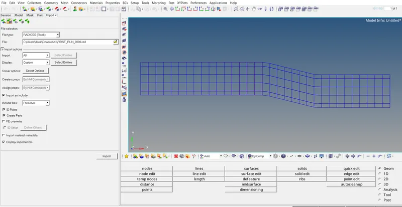
- we can import the Slover deck in HyperWorks by >>import>>import Slover deck>>choose file>>import
2. After importing the FIRST_RUN_0000.rad, we have to go >>model>>material>>steel we will see the name card
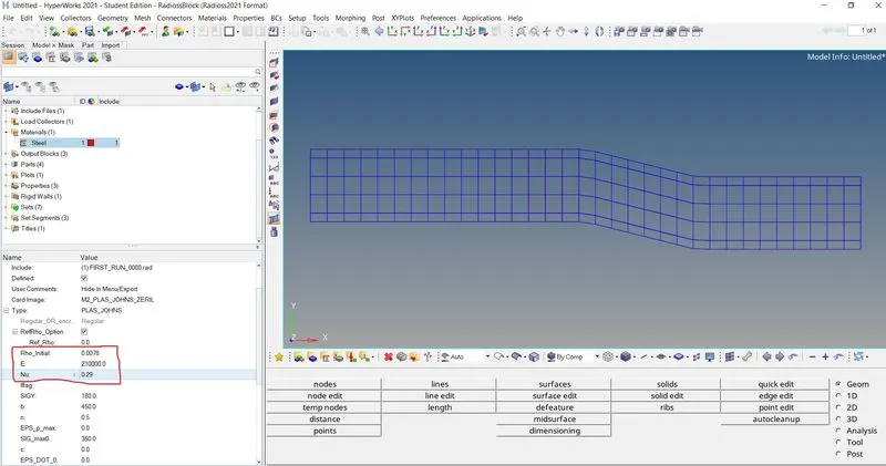
- Youngs modulus(E) N/mm2 = 210000
- density (Rho) kg/mm3 = 0.0078
- Poisson's ratio (Nu) = 0.29
3. Now Speed of sound in the rail is given by the formulae
Speed of sound in the rail c =` sqrt(E/(Rho)`
c = `sqrt(210000/0.0078`
speed of sound in the rail c = 5188.745 mm/sec
4. Now, time is taken for the shock wave to travel from one end to other end is given by
The length of the rail l = 1000 mm
time taken `triangle T`=`l/c`
`triangle T= 1000/5188.745`
Time taken for a shock wave to travel from one end to other ends `triangle T=0.192724`ms
5. Time for sound to travel the length of rail = 0.192724 ms
5. Time for sound to travel the length of rail = 0.192724 seconds
6. Now, we have to edit the FIRST_RUN_0001.rad file to our requirements
- we can simply edit the Radioss file in note pad or we can import the file to the Radioss slover deck and make the necessary changes
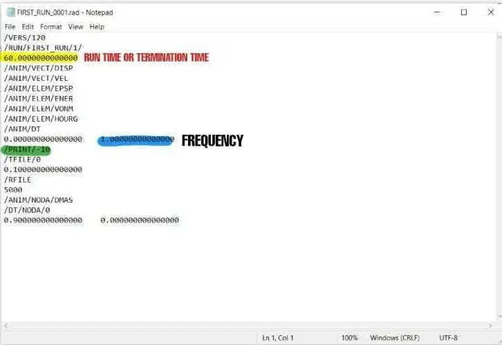
file before editing
7. The frequency of animation output to a time that will give 20 animation steps is given by
Frequency Tfreq= Termination time/ number of steps
Tfreq = `0.1927248223/20`
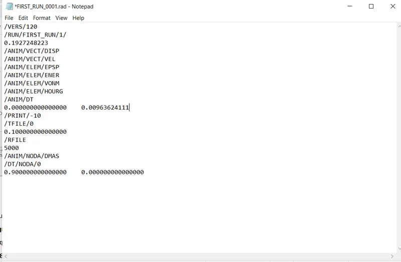
Tfreq = 0.00963624111 ms
8. The edited engine file is as shown below
# 3D MESHING
(I) Arm bracket:-
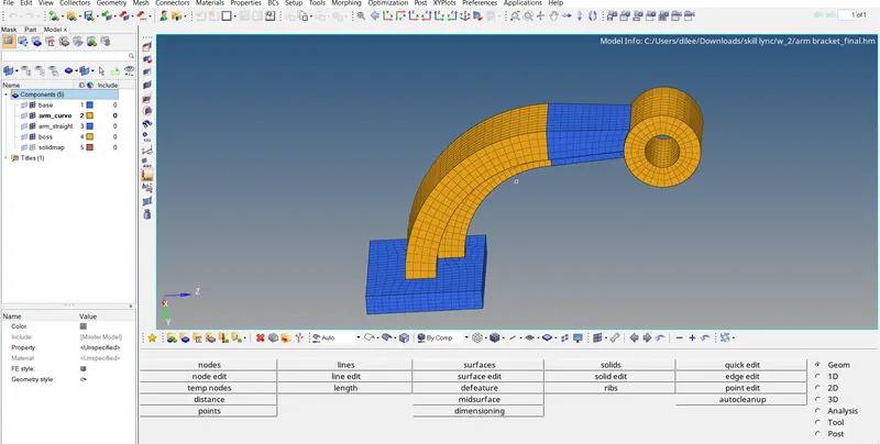
1. we have to import the .hm file into the hyperworks software and the 3 d model have different which are base, arm curve , arm straight and boss. we can mesh the arm backet my meshing individual components and combining them.
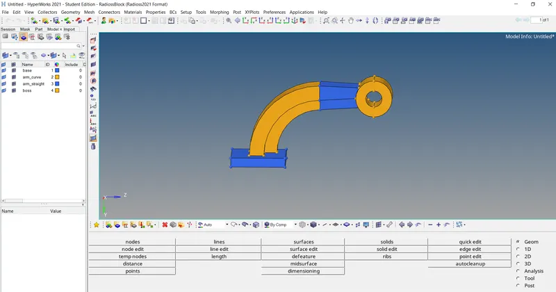
- Meshing of base
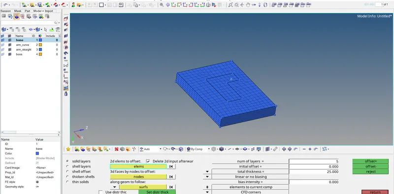
2.We will start meshing bycreating a 2d mesh on the surface of base by hiding all other components and considering base as the current component. While creating a 2d mesh, our aim is to create a hexa mesh so we have to assign the mesh design as quads only. after creating mesh we have to offset the elements with proper thickness and offset layers. Below steps to be followed while creating mesh of base:
- import>>import model>>(hiding other components and making base as current component)
- automesh>>mesh>>quads only>> mesh
- 3d>>element offset>>solid layer >>element selection>>along geometry selection>>number of layers >>total thickness>>offset
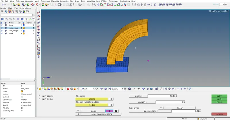
3. Now, we have to switch on the arm curveand make the arm curve as current element by hiding the 3d elements of base. After hiding 3d elements of the base, being a curved geometry we can use spin feature for meshing. To use spin feature we need the center of that curve which can be find by using any three nodes on the curdeved surface. after finding center we can go through the spin feature by selecting the proper assigning components like spin angle, spinning of 2d elements density etc. the following steps to be followed which meshing the arm curve:
- after making the arm curve as current component
- mask elements>>mask>>element>>element config>>hexa 8>>select entities >>mask
- (for center of curved surface) distance>>three nodes>>(select any three nodes then there will a center point is created)
- 3D>>spin>>spin elements>>2d elements>> plane of spin>>center of curved surface>>angle of spin>>onspin>>spin+ or spin -
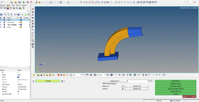
4. Arm straight can be meshed by using linear solid because, the mesh on both sides is same but different croseesection. we can create the faces of arm curve and then the 2d meshing is on the opposite sides of arm curve face. after creating we have to hide the arm curve. after creating 2d mesh, we have to check the number of elements homogenisity of the two faces , after optimising we can go through linear solid for meshing. after creating linear map, setting arm straighter as current component , we have to organise the created linear solid elements and we can delete the surfaces.
- tool>>faces>>components>>find faces
- a two 2d mesh is created on the created face and assigned same number of elements on both faces
- tool>>organise>>collectors>>element selection>> move
- the created faces can be deleted bny using delete of face delete tool
-
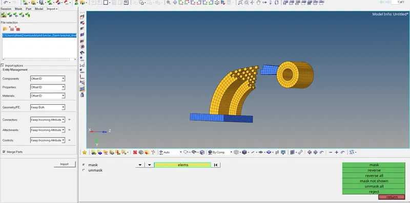
5.Now For meshing of Boss, solid mapfeature is used. for this feature usage we have to make one circular face of boss is meshed with same number of nodes in order to have QUAD elements. After creating 2D quads, we have to project and duplicate nodeat the end so that all the elements can be make from one end to other. we can use solid map feature for boss meshing in which we have to select Destination surface use mixed option to select node by path and line between source and destination surface. One component with name of Solid map is created make sure to organize all elements from it to boss part.
- A 2d mesh with same number of quads elements is created on one of the surface of boss
- tools>>project>>surface>>node>>duplicate>>surface>>plane of projection
- 3d >>solidmap>>source geometry>>none>> destination geomtrey>> along geometry >>mixed>>elemts>>line>>nodes list>>solid map
- all 2d elements are delegated by using delete entity tool and its is organised to move to original component
#Housing
1. we have to import the .hm file of the hosing into the hyperworks software and the 3 d model have different components which are hub and cover
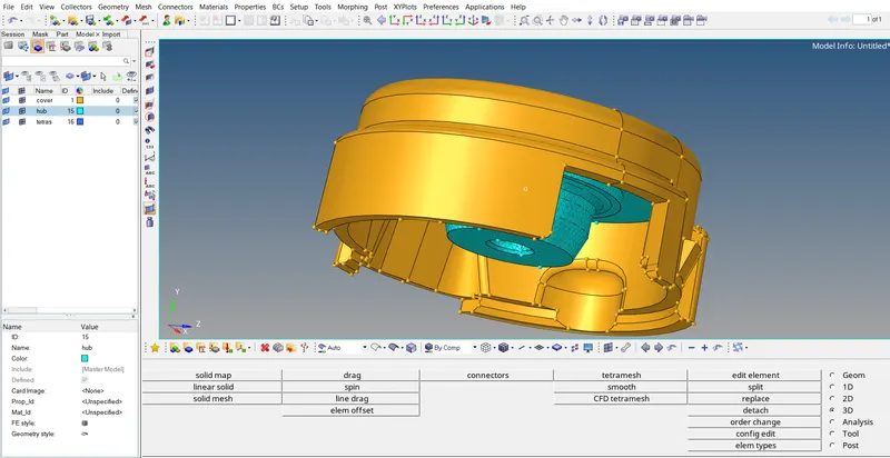
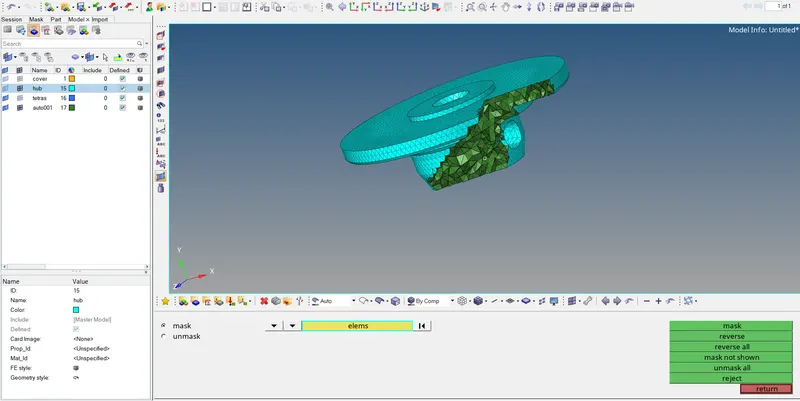
2. Now for hub, we have to create a 2d mesh surface with trias elements with element size 5 mm. after creating 2d mesh we can create 3d mesh by tetramesgh feature in 3d panel.
- 2d>>automesh>>surf>>trais>>mesh
- 3d>>tetramesh>>tetramesh components>>tetramesh>>elems>>mesh
3. Now for cover, we can follow the same procedure for meshing but we will go through other method
- view>>browsers>>hypermesh>>utility>>geom mesh>>quick tetramesh>>components>> trais only>>mesh
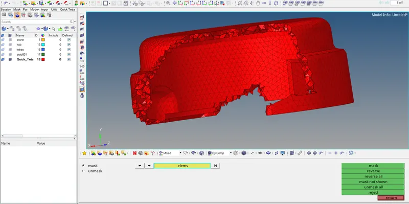
the final part is as shown below