Assignment 7-Side Pole Crash Simulation Challenge
Aim: To perform Side crash analysis on body in white component by considering recommended parameters.
OBJECTIVE:
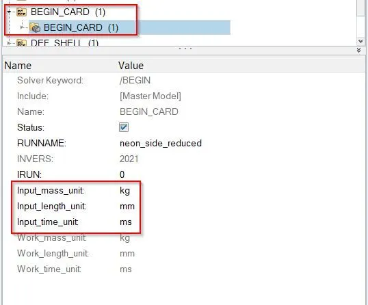
- Check unit system and either follow [Mg mm s] or [Kg mm ms].
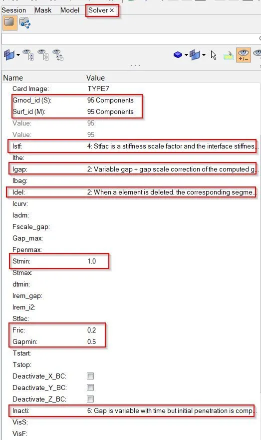
- Create appropriate interface with recommended parameters and friction force is 0.2.
- To check the penetration and intersection between components.
- To create rigid wall with friction 0.1 between car and rigid wall.
- Adding extra mass to attain target mass of 700kg.
- Adding initial velocity of 35 mph.
- Run model checker to ensure good quality.
- To apply timestep between 0.5 to 0.1 microsecond.
- To find sectional force in the cross members.
- To calculate intrusions at B pillar, hinge pillar and fuel tank region.
- To calculate peak velocity of inner node of door.
- To plot all the required results.
PROCEDURE:
Open the hyperwork software, and then we have to set user profile interface i.e. Optistruct or RADIOSS. Optistruct is implicit solver which handles small deformations. And RADIOSS is explicit solver which handles large deformation. So we will use RADIOSS as user interface.
First we have to import the required file i.e. neon_side_reduced_0000, which is in .rad format. So to import the .rad file format model in hyperworks, we have to follow:
File--->Import---->Solver Deck---->File: select file--->Import.
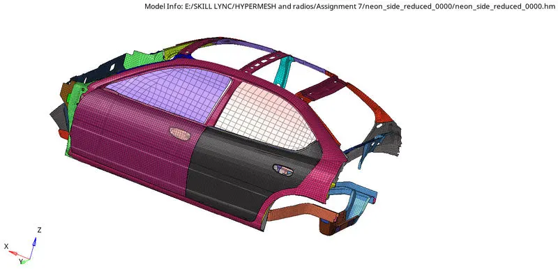
Once model is opened, it will look like as shown picture in below.
- Check unit system and either follow [Mg mm s] or [Kg mm ms].
In order to check unit system, we have to follow:
Model Browser---->Cards---->BEGIN_CARD
- Create appropriate interface with recommended parameters and friction force is 0.2.
Once unit system is checked. Now we have to create appropriate interface. In model there are different interfaces are present, so we have to delete the default interfaces as shown in picture below.
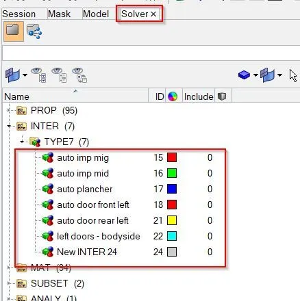
Therefore, in order to create the interface of Type 7, we have to display solver browser by clicking
View---->Browsers---->HyperMesh---->Solver.
Once solver browser is displayed. Now we have to create appropriate interface i.e. Type 7 with recommended parameters as shown in picture below.
Solver---->INTER---->press right click on INTER---->Select create---->TYPE7.
- To check the penetration and intersection between components.
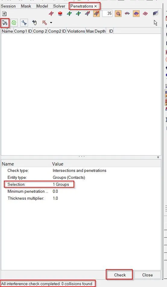
There should not be penetration and intersection between components. In order to check the penetration, we have to follow.
Tools---->Penetration check---->Select group---->Check.
- To create rigid wall with friction 0.1 between car and rigid wall.
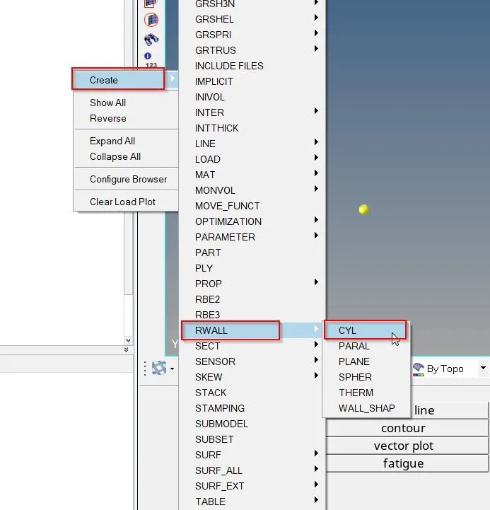
In order to create rigid pole instead of rigid wall, we have to follow:
Solver---->Create---->RWALL---->CYL
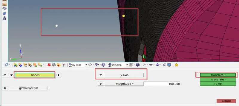
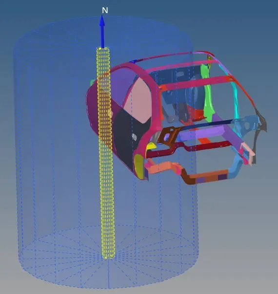
To make a rigid pole, we need to create a reference node. First we will create a temporary node at the side door. After then we will translate that node to create a gap between car and rigid pole as shown in picture below.
In rigid wall, we have to create the recommended properties by selecting the temporary node in XM,YM,ZM then enter the search distance Dsearch of 1000 and friction value of 0.1.
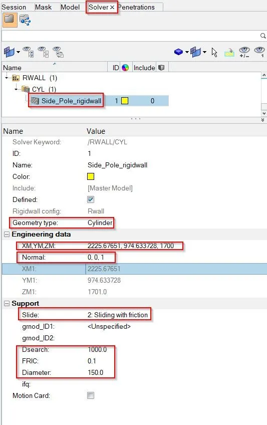
Once rigid pole is created, model will look like as shown in picture below.
- Adding extra mass to attain target mass of 700kg.
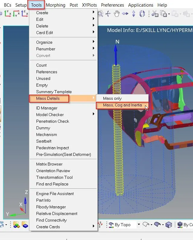
In order to check the mass, we have to follow:
Tools---->Mass Details---->Mass, COG and inertia
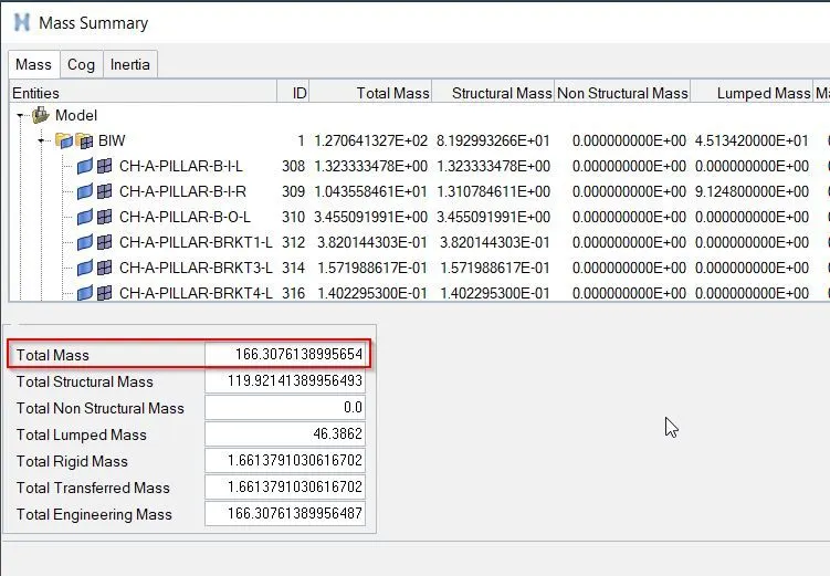
Therefore, in this model we have a total mass of value approximate 166 kg as shown in picture below. But in 300k nodes model we have a target mass of value 700 kg.
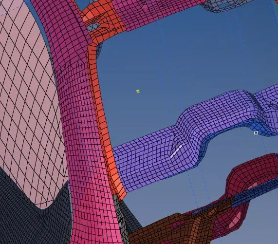
And COG for current model lies at point as shown in picture below.
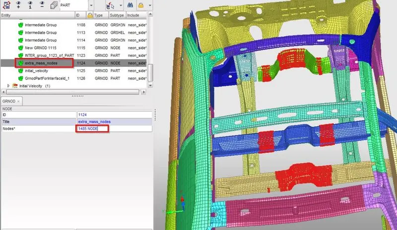
Now we have to add masses to increase overall weight of car by assigning GRNOD ID
We have to follow:
Solver---->press right click to create---->ADMAS
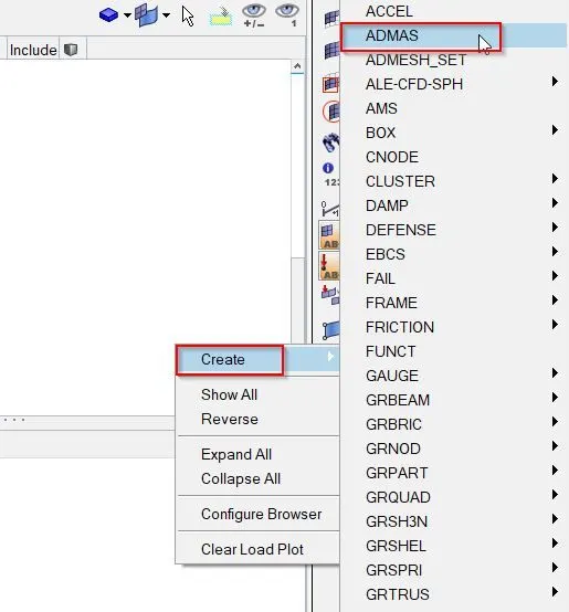
Therefore, in order to create the mass. First we have to select the nodes as shown in picture below.
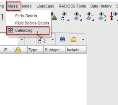
In order to check the mass and COG value in hyper crash, we have to follow steps shown in picture below.
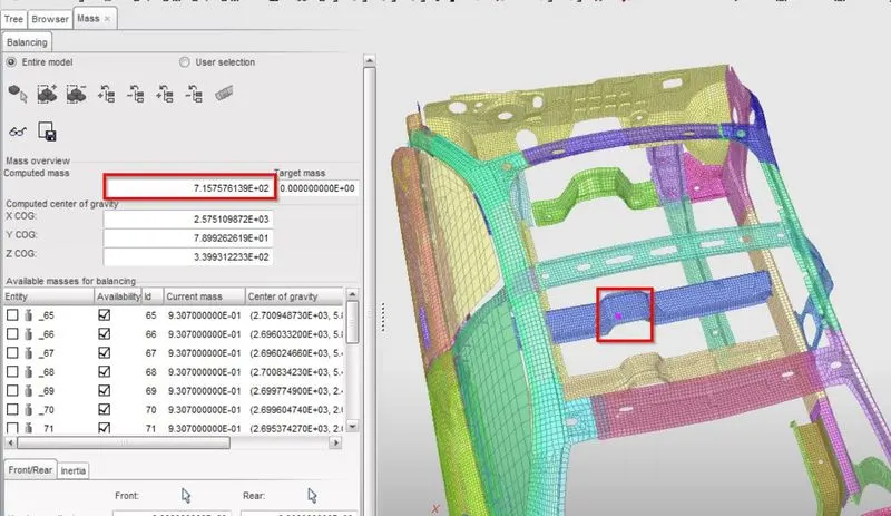
Once above mentioned process is done, now we can check value of mass and COG as shown in picture below.
- Adding initial velocity of 35 mph.
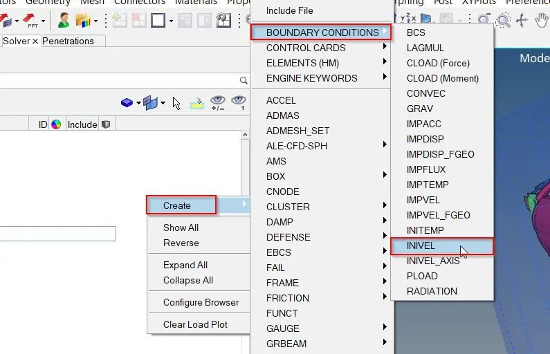
First we have to create a INIVEL card as shown in picture below, by following:
Solver---->Create---->BOUNDARY CONDITIONS---->INIVEL.
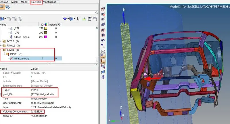
Now we will provide recommended parameters as shown in picture below initial velocity of 15.65 mm/ms in translational y-direction and remaining two dimensions will remain constrained.
- Run model checker to ensure good quality.
We will use hypercrash to run the model checker. In order to switch model from hyperworks to hypercrash. We will export the .rad format file by following:
File---->Export---->Solver Deck---->File: select location---->Export.
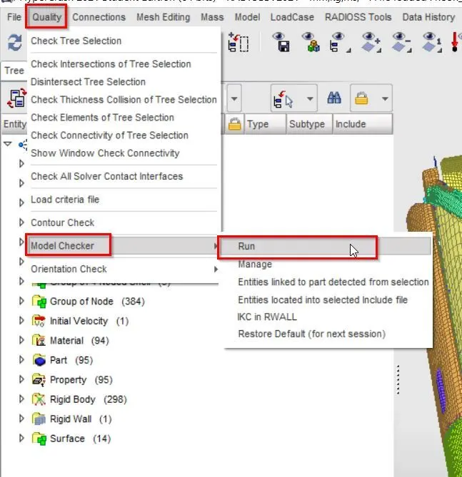
Then we will open .rad file in hypercrash. Now in order to run the model checker we have to follow steps as shown in picture below.
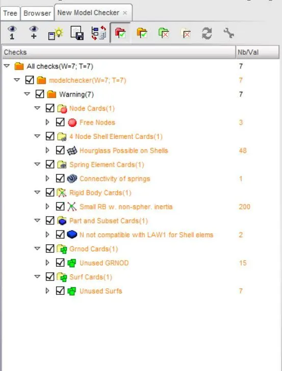
Once model checker is done, report will generate as shown in picture below.
- To apply timestep between 0.5 to 0.1 microsecond.
We have different methods to create time step such as INTER, NODA, BRICK, QUAD, SHELL, TRUSS, BEAM, SPRING etc.
And we have different time step control such as CST, CST1, CST2, DEL, STOP, AMS.
In this case we have created INTER and NODA as a type of time step control.
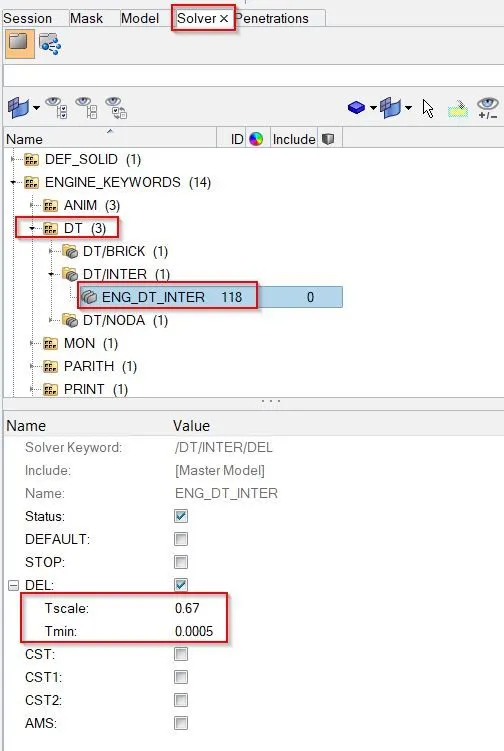
8.1. ENG_DT_INTER
This method is used in order to control the time step.
A type of time step option is “INTER” and time step control “DEL” is used.
We have to keep 0.67 as time scale factor and 0.0005 as a minimum time step control.
If time step gets reduced below the minimum time step, then this algorithm will add some mass to the element which leads to maintain time step more than minimum time step.
8.2. ENG_DT_NODA:
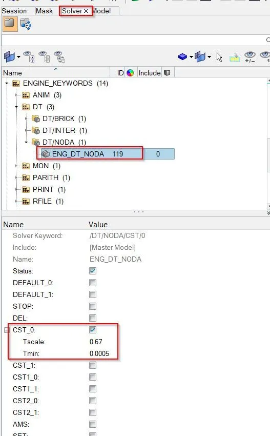
This method is used to control the time step from the nodes.
A type of time step option is “NODA” and time step control type “CST” is used.
In order to create ENG_DT_NODA we have to follow steps as explained below.
- To find sectional force in the cross members.
The results which we want on required cross-sectional parts is based on axis of reference.
In order to create SECTION, first we have to create the FRAME CARD on particular node of that section which is called as local axis. In this moving frame is attached with the nodes which is selected as origin.
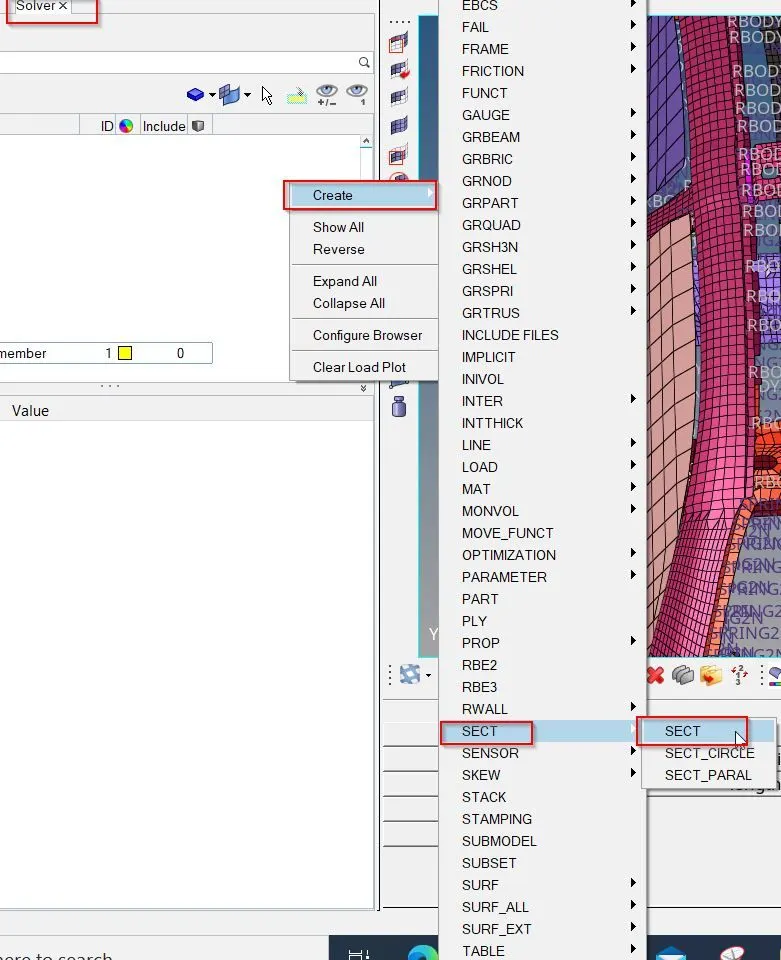
Now, we have to create FRAME card in solver browser. In order to create FRAME card, we have to follow:
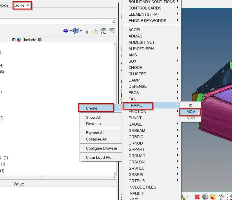
In order to assign parameters in FRAME---->MOV, we have to follow. In this we have to define origin node and then define the z-axis with second node which is in the direction of crash. And then we have to define the third node for plane as shown in picture below.

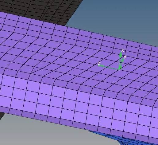
Once axis has created, it will look like as shown in picture below.
Now we have to create the SECTIONAL force at first cross member. In order to create SECTIONAL force, we have to follow:
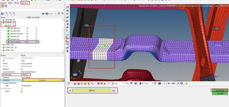
First we have to create GRSHEL card by selecting elements as shown in picture below.
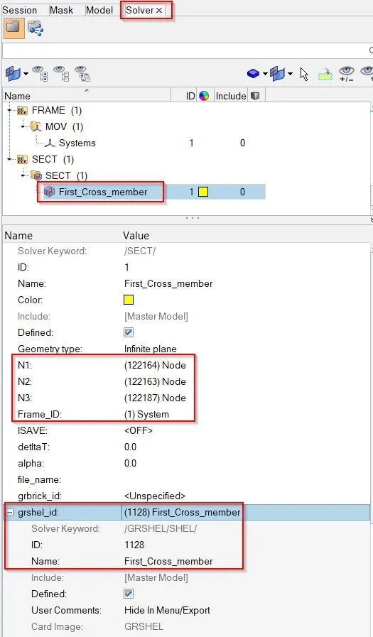
Now we have to assign this GRSHELL id in the SECT parameters as shown in picture below.
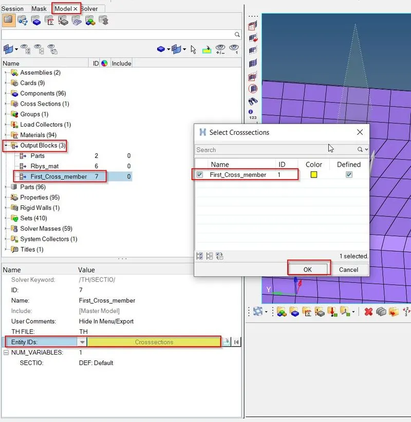
Now we have to give output blocks request in model browser as shown in picture below.
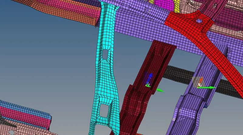
Similar steps will be performed to create sectional force at second cross member. Once above steps are done model will look like for both cross members are as follow.
- To calculate intrusions at B pillar, hinge pillar and fuel tank region.
Spring element is created to understand intrusion which means how the forces are coming inside the car cabin. In order to create intrusion spring, first we will create component id as shown in picture below.
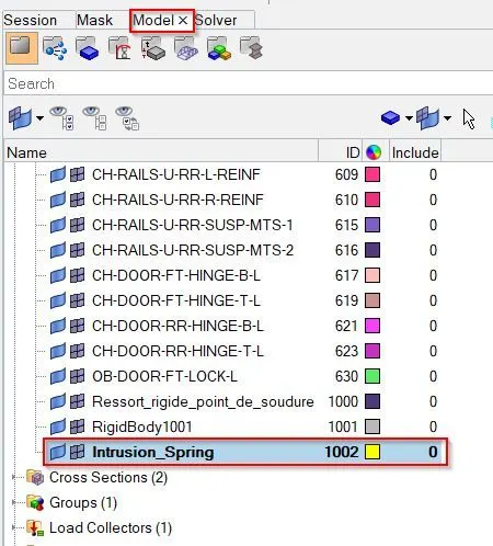
In order to create spring, we have to follow
1D---->Springs
 |
 |
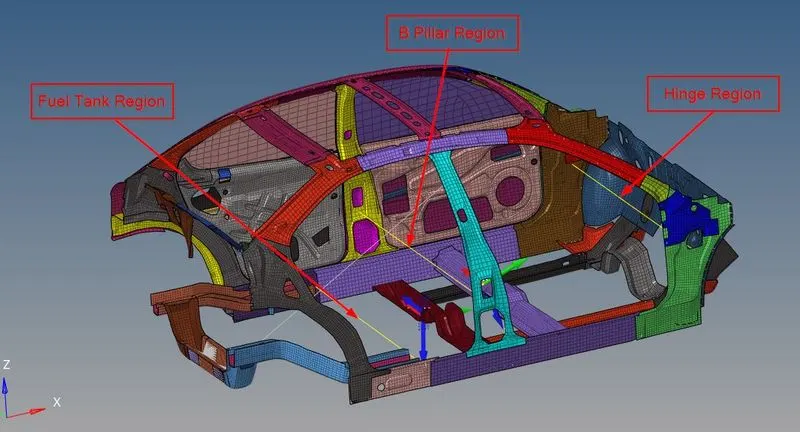
Once springs are created at Hinge region, B pillar region and fuel tank region as shown in picture below.
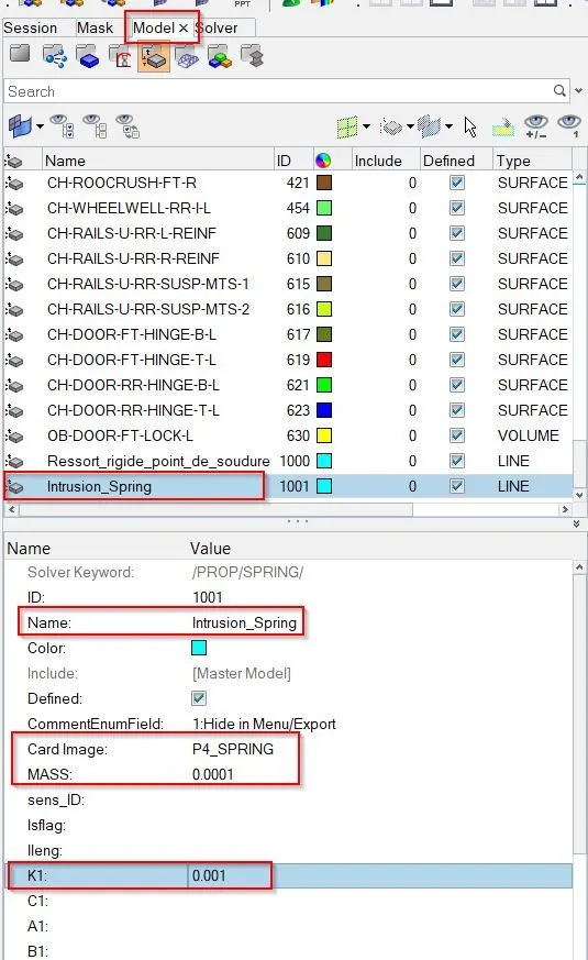
Once springs are created, now we have to create property id for spring with required parameters i.e. mass of 0.0001 kg and stiffness of value .001 kg/mm as shown in picture below.
Now we will assign spring property id card as shown in picture below.
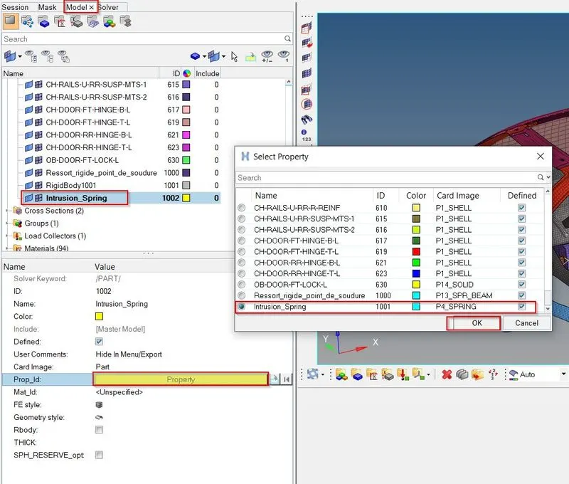
Now we will create time history, for the created spring by following steps mentioned in picture below.
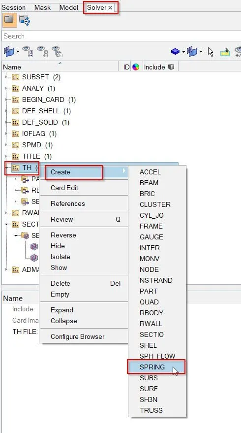
Once time history is created for all the springs, cards will look like as shown in picture below.
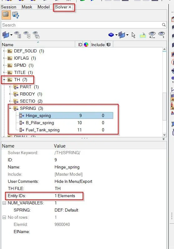
- To calculate peak velocity of inner node of door.
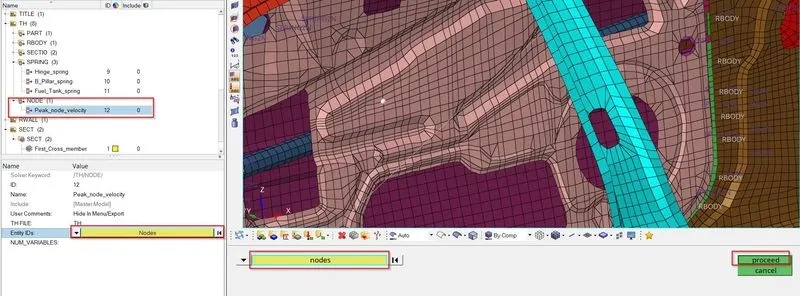
In order to calculate peak velocity at inner node of door, first we will create temporary node, where we want to calculate peak velocity. Now we will create node time history as shown in picture below.
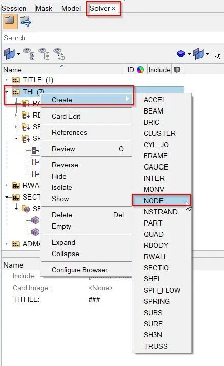
Once card is created, now we rename and select the required nodes as shown in picture below.
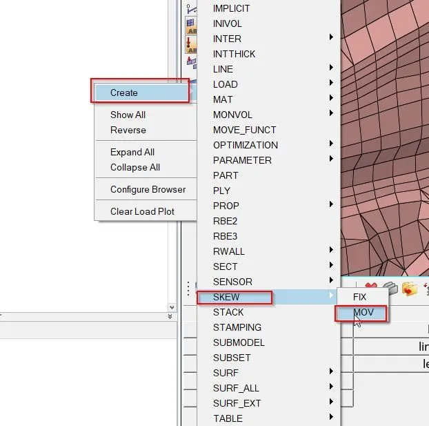
Now we have to create moving frame at the node location by right click in solver browser as shown in picture below.
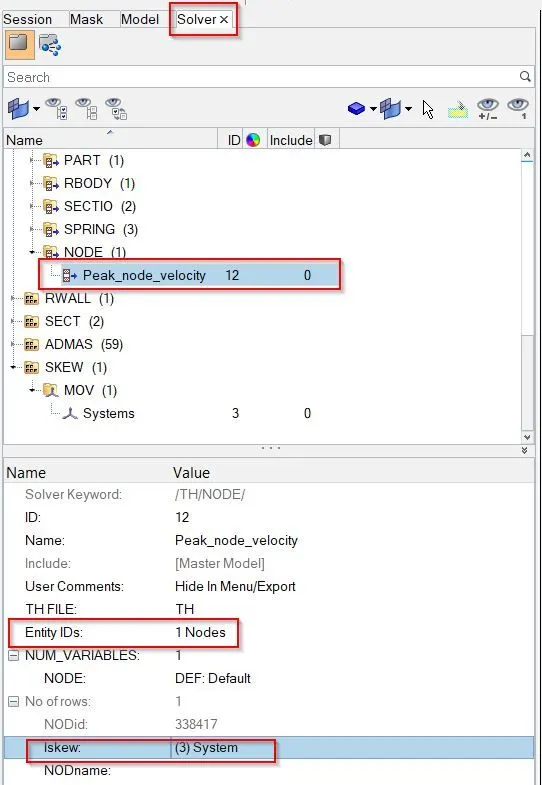
Now we have to assign skew id as shown in picture below.
Simulation on the SIDE CRASH:
Now we can check the animation by run the simulation with default properties by following:
Analysis---->Radioss
Now we have to give location to export the input file:
Options helps to choose number of cores to solve this problem, here we have chosen 4 number of cores by (-nt 4).
Then click on Radioss, and new window will get pop-up. A simulation will start to show result,
After run the simulation on model, solver has generated different files such as engine listing file, animation, time history and then restart file.
Now, in order to check the energy error and mass error. We have to open the output file in notepad.
Once output file is opened, we can see the results.
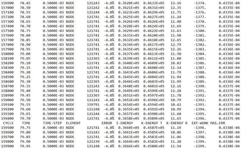
Time step is calculated at every cycles. If model time step value is less than 0.0005, then solver will take default time step value i.e. 0.0005. Because we are using “CST” which means solver will use default time step value, if model time step value falls below nodal time step. To keep time, step constant, it will add some mass on the node for which control the time step.
In zeroth cycle model time step is less than nodal time step. Control method has to be used constant time step having value of 0.0005 and mass has been added on the nodes. So, energy error is -4.0% and mass error is .0004 which is acceotable.
An error is positive which means some energy is generated in the body.
Now we have to switch from Hypermesh mode to Hyperview mode. Then we have to select the appropriated (.h3D) file. And then we have to click on Apply to view the results.
By using different animation controls, we can check and animate the results as shown in picture below.

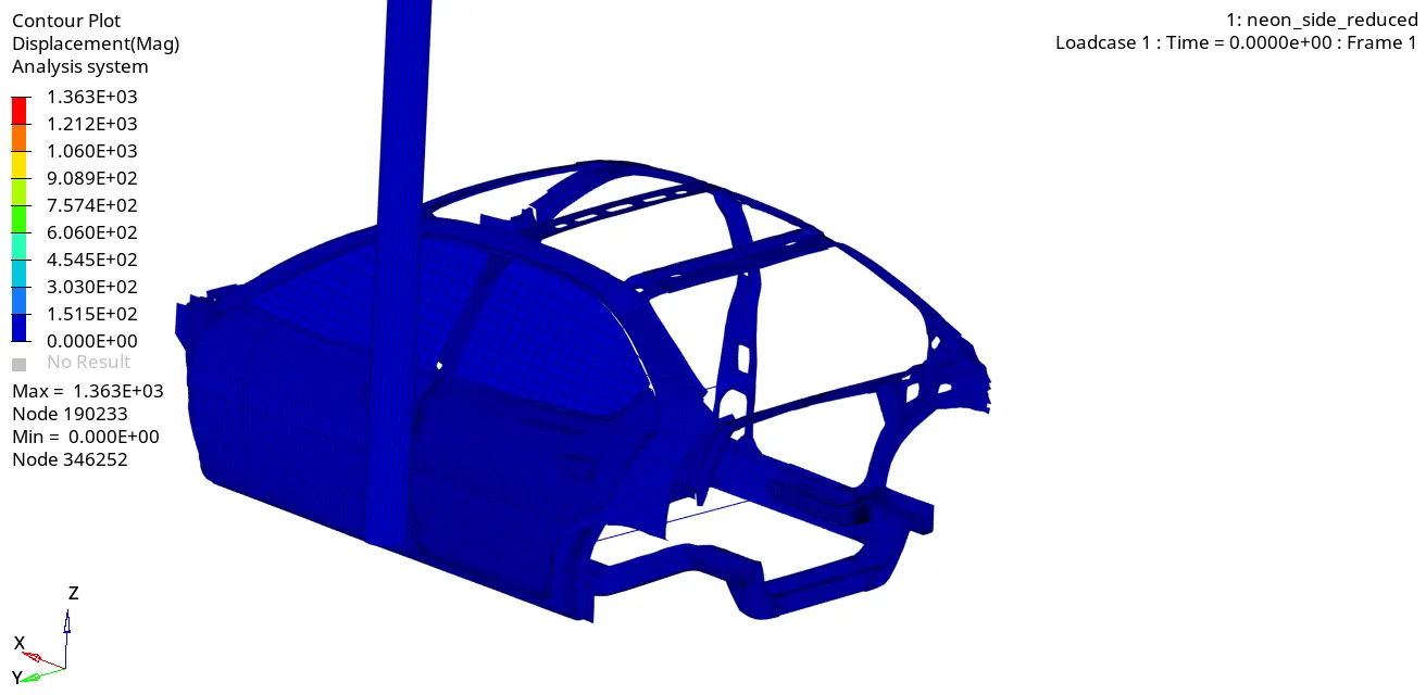
Contour plot for Displacement
Maximum displacement reaches up to 1363 mm over the period of time.
From below we can see BIW vehicle side crash with pole. After the impact, frame of the vehicle gets deformed, and vehicle body gets contracted around the pole. This is due to reason that center of gravity of the car lies at same direction of pole.
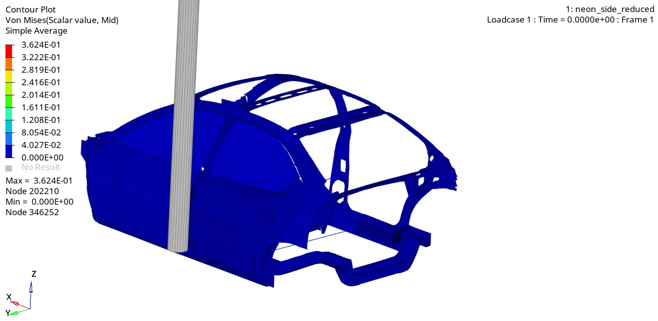
Contour plot for Von Mises
More stress is generated at the region of B pillar and also at region of cross rails, And value of von misses stress seems to be low because applies initial velocity is low.
HYPERVIEW
Now we have to switch from HyperView mode to HyperGraph 2D mode.
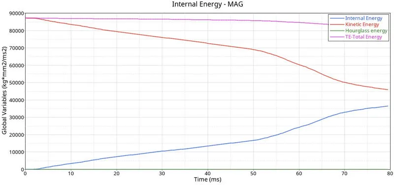
ENERGY PLOT:
As we can see, from below graph that kinetic energy is decreasing from starting time to termination time. Because a velocity is decreased over a period of time. Kinetic energy is directly proportional to velocity. Kinetic is started at 85000 and ended up with 45000.
Internal energy is increased over a period of time. Because it has some work done in the car.
And no hourglass energy is dissipated, since QEPH formulation has been used.
As we know total energy is the combination of internal, kinetic energy which has been plotted below.
Once all parameters are filled, we have a required graph as shown in picture below.
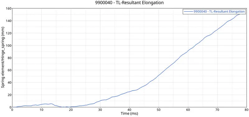
Intrusion of hinge component:
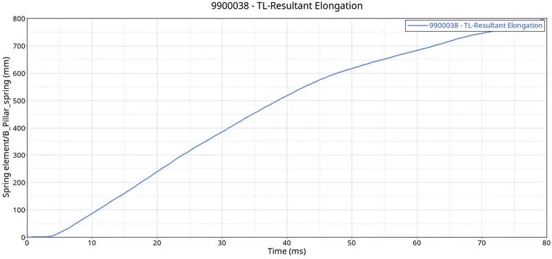
The intrusion or deformation of the vehicle component can harm the occupant. So, we can see the maximum intrusion at hinge region is 160mm. It is around 800mm of intrusion received at B pillar region. And approximate of around 820mm of intrusion received at fuel tank region.
 |
 |
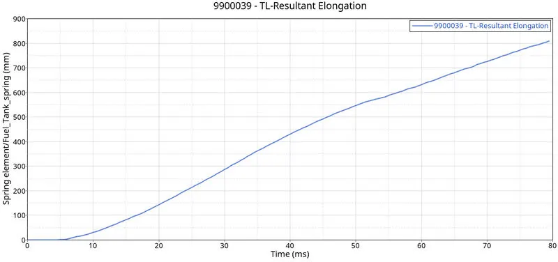 |
The impact of intrusion can be reduced by adding additional cross member at fuel tank. Which can help to absorb deformation.
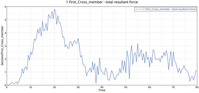
Sectional forces at first cross member:
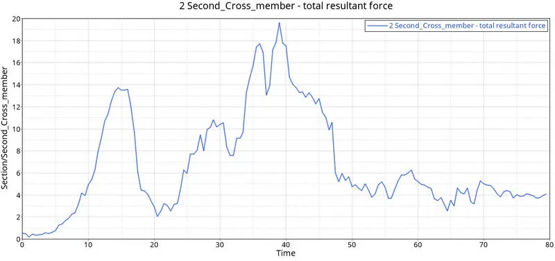
Sectional forces at second cross member:
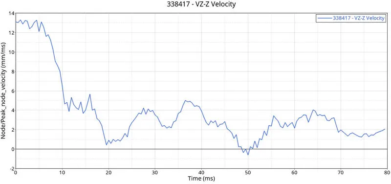
Peak velocity of node and inner side of door
From below graph, it can be observing that initial body move with some velocity. Once the impact of side of vehicle is done with pole. The velocity start decreasing around 5ms.
CONCLUSIONS
- Simulation has been done successfully on given BIW model as per given requirement.
- All the output requests have been calculated such as sectional forces, peak velocity of inner side of door and intrusion.