Assignment 6-Frontal Crash Simulation Challenge
#Assignment 6
Frontal crash of BIW Structure of the CAR
Aim: To create a deck setup for FRONTAL CRASH OF BIW of the car and request for the TH(Time History file)
OBJECTIVE:
- Check unit system and either follow [Mg mm s] or [Kg mm ms].
- Create appropriate interface friction 0.2 and recomended parameters.
- Make sure of no penetration and intersections, correct rigid body if any issue.
- Create Rigid wall with friction 0.1.
- Added mass to reach target weight of 700kg while getting CG about the required range.
- Initial velocity 35 mph.
- Time step: 0.5 to 0.1 microseconds
- Run time 80ms
Output Request:
- Section force in the rails at location indicated node 174247
- Axial force recieved on the rails from the bumper.
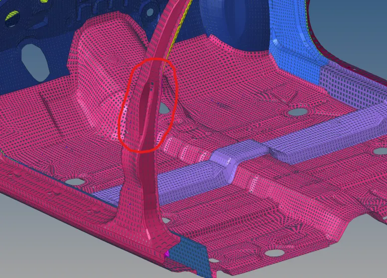
- A-pillar cross-section.
- Accerlation curved recieved on the accelerometer at base of B-pillar (on B pillar rocker).
- Intrusion on the Dashwall 110020, 110021
Theory:
A crash Test for vehicle saftey is a type of destructive testing undertaken to ensure that standards for safe design with regards to crash compatability and crashworthiness are followed for different transport modes.
Crashworthiness is the ability of the vehicle to safe or protects its occupant, occupant protection can be achieved by ability of vehicle to absorb crash energy by controlled vehicle deformation.
Crash is the explicit analysis. Explicit analysis is used to determine the dynamic response of a structure due to stress wave propagation, impact or rapidly changing time dependent loads. Momentum exchange between moving bodies and interial effect are usually important asspects of the type of analysis being conducted. This tyoe of analysis can also be used to model mechanical phenomena that are highly nonlinear, Non-linearity may coming from the materials called as material nonlinearity, from contact(high speed collision and impact) and from the geometric deformation(buckling and collapse). Events with time scale less than 1 seconds (usually of order milliseconds) are efficiently simulated with this type of analysis, based on these condition user will select an explicit solver to solve the analysis. Typical example of explicit analysis are crash analysis, drop test, bird strike, fan blade out.. etc, Obtaining an answer from an explicit simulation can be simple, but it can be more challenging to get the correct answer, The pridiction of simulation are not easy. Nonlinear analysis requires a lot of experience and carefull understanding of the software's capabilities, and also we have to compare the simulation results with the physical test results.
Types of crash testesd
- There are majorly three types of crash named as frontal, side and roof crash.
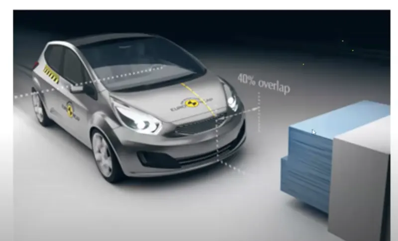

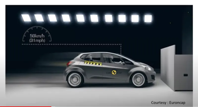
Frontal crash
Source: Global-NCAP / EURO-NCAP
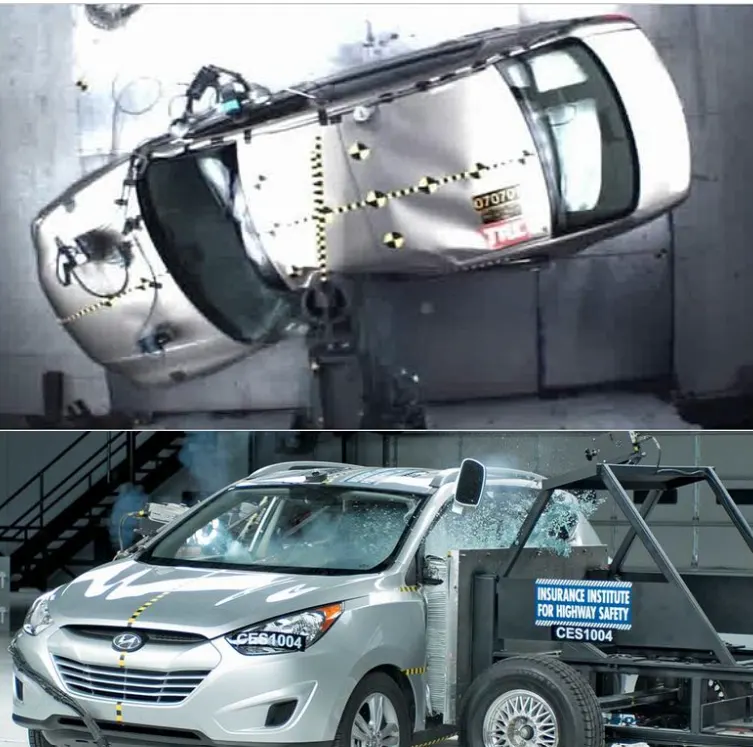
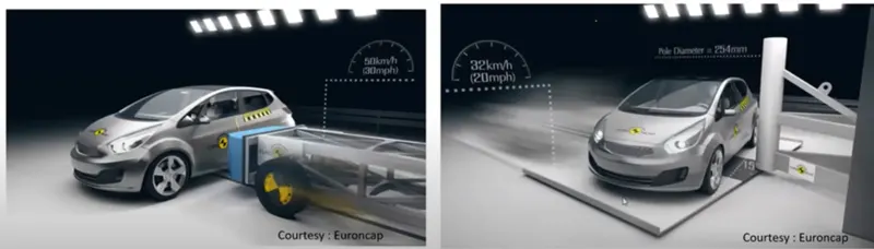
SIDE POLE Crash / SIDE Crash
Source: IIHS / EURO-NCAP
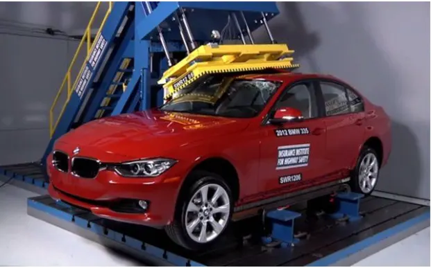
ROOF Crash
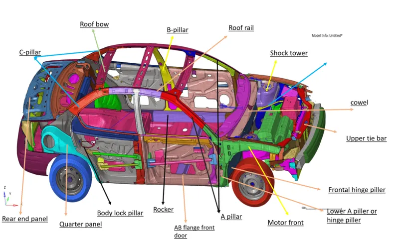
BIW terminologies
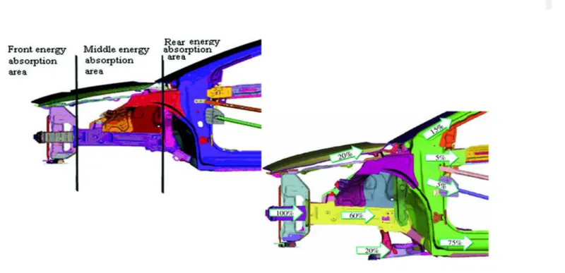
ENERGY ABSORPTION ZONE IN CAR STRUCTURE
Procedure:
- Import the file by using import option in Hypermesh.
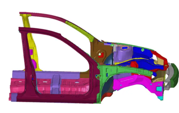
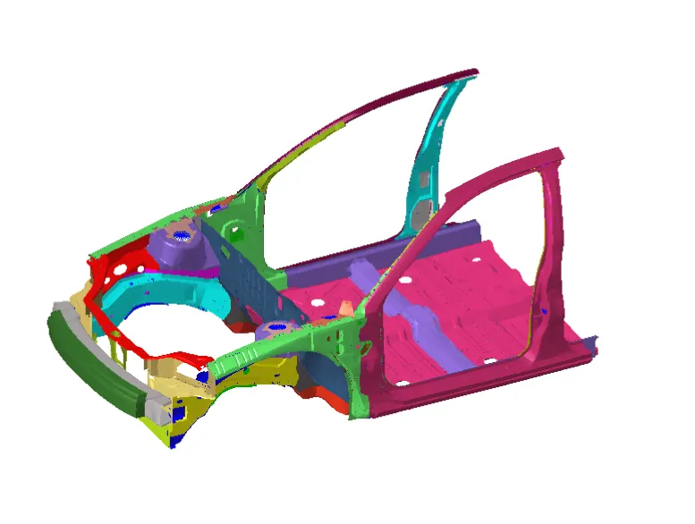
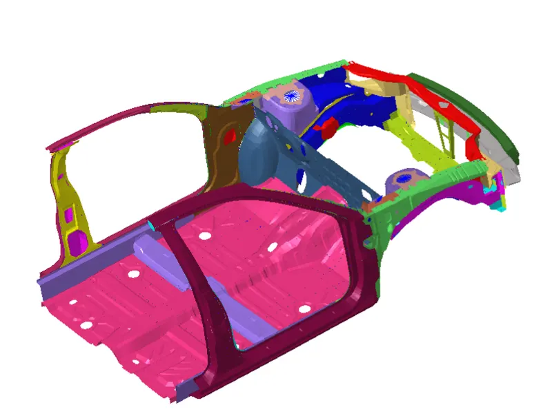
Extracted BIW component of the car (NEON FRONT)
2. SETUP for the FRONTAL CRASH OF NEON FRONT
- Check unit system and either follow [Mg mm s], [Kg mm ms].
To check the unit system either you can open the 0000.rad file (Starter file) in notepad or either you can check the imported units in BEGIN-Card
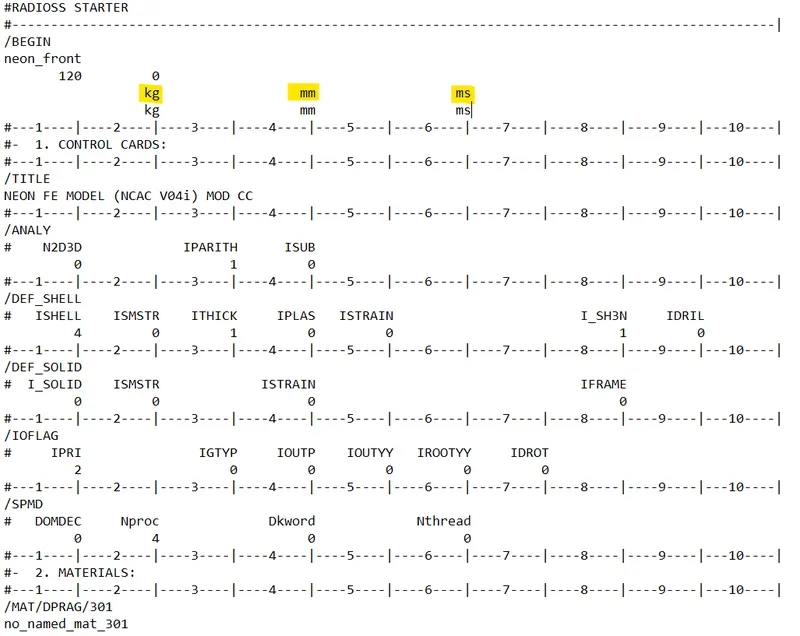
Checking unit system in Starter file
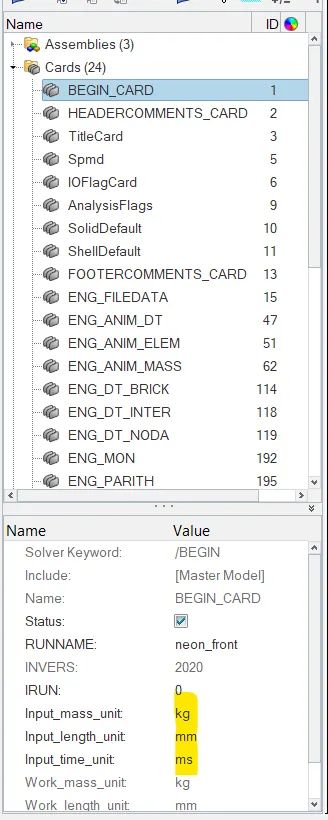
Checking unit system in BEGIN_CARD
- Create appropriate interface, friction 0.2 and recomended parameters.
Here we have to create the interface as self contact interface (Type7) for all the model, Here we have already previously created interfaces, we can't use them because in the above model some parts are missing and due to this we can't use these interfaces, we simply delete them, after deleting the interfaces we can create the TYPE7 interface as self contact interface with recomended parameters.
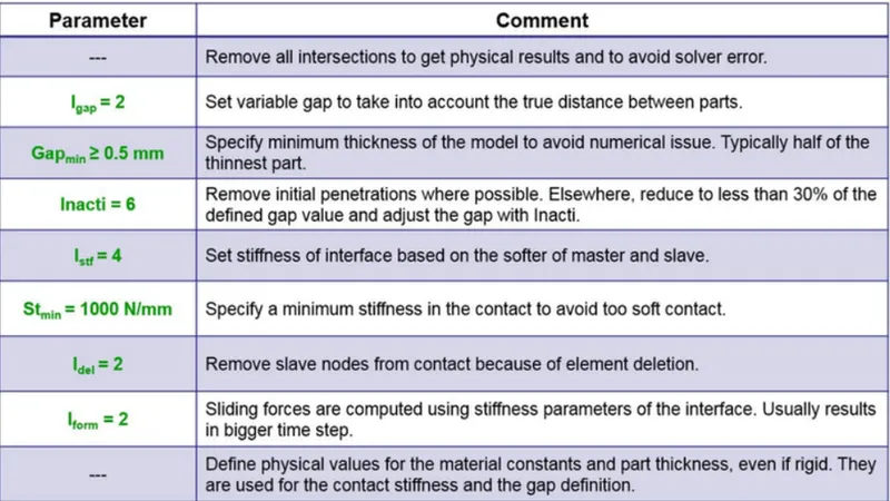
Recomended parameters for Type7 Interface
- To create interface go to solver browser right click and create interface and select as TYPE7, define the slave nodes and master elements.
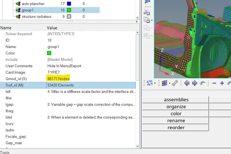
Defining the Slave nodes and Master elements
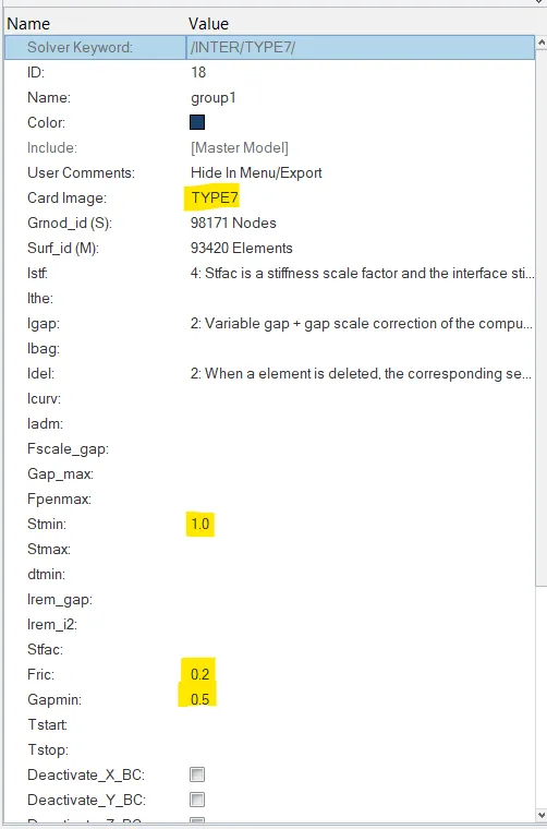
Defining recomended parameters
TYPE 7 interface has been created
- In similar manner we have to create the Interface between Bracket and Bumper where Bracket is Master and Bumper is slave
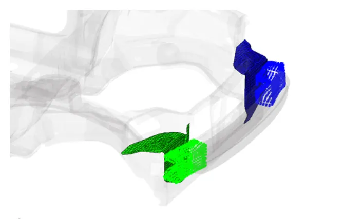
- Make sure of no penetrations and intersection. connect rigid body if any issue
To check penetration we can use both Hypermesh and Hypercrash, Hypercrash are more sphasticated then the Hypermesh, so we are using Hypercrash to check the penetration, also we can simply check in the Hypermesh as well
To check Penertation and Intersection in Hypermesh go to Tool >> Penetration check, if any penetration occur use auto penetration fix option to fix the penetration.
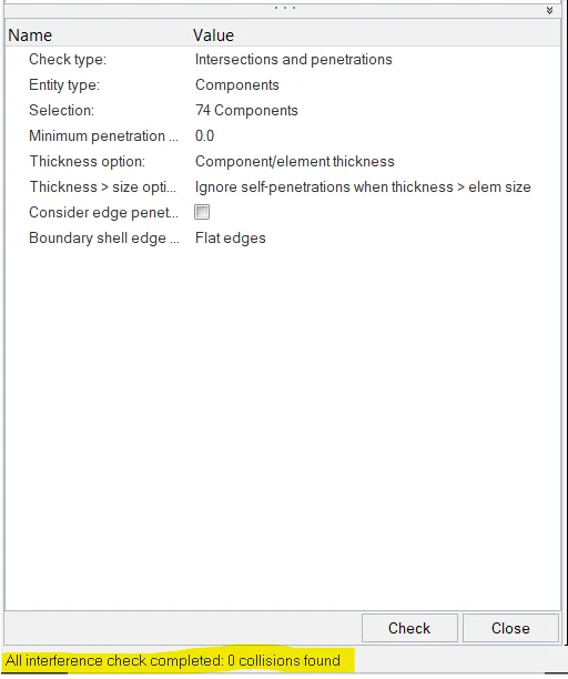
No penetration found
There are no penetration issue found in the model and also there is no issue in the rigid bodies, but here there are lot of un-necessary rigid bodies are present, we have to be remove them from the model to clean the model.
- Create Rigid wall with friction 0.1.
To create rigid wall go to Solver >> Create >> Rwall > plane, define the sliding friction value and give search distance of 1000
Note: During creation of Rigid wall make sure that you define the head and tail of the rigid wall correctly, and make sure that there should be minimum gap of 5 to 10 mm between cars head and rigid wall, for increasing distance or to make a gap we have to change the Head co-ordinates.
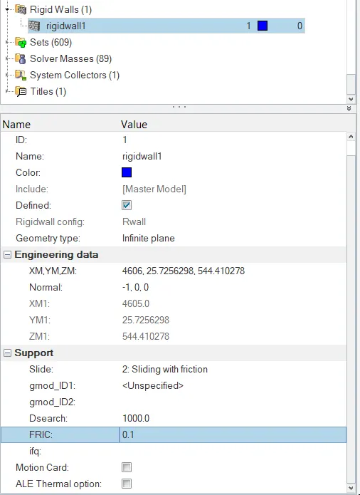
Defining parameters for Rigid wall
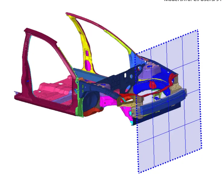
Creating a Rigid wall
- Mass balancing and Added mass to reach target weight 700 kg, while getting CG about the required range.
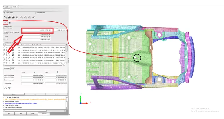
Initial Mass and COG location
To add mass go to Solver >> Create >> Add mass
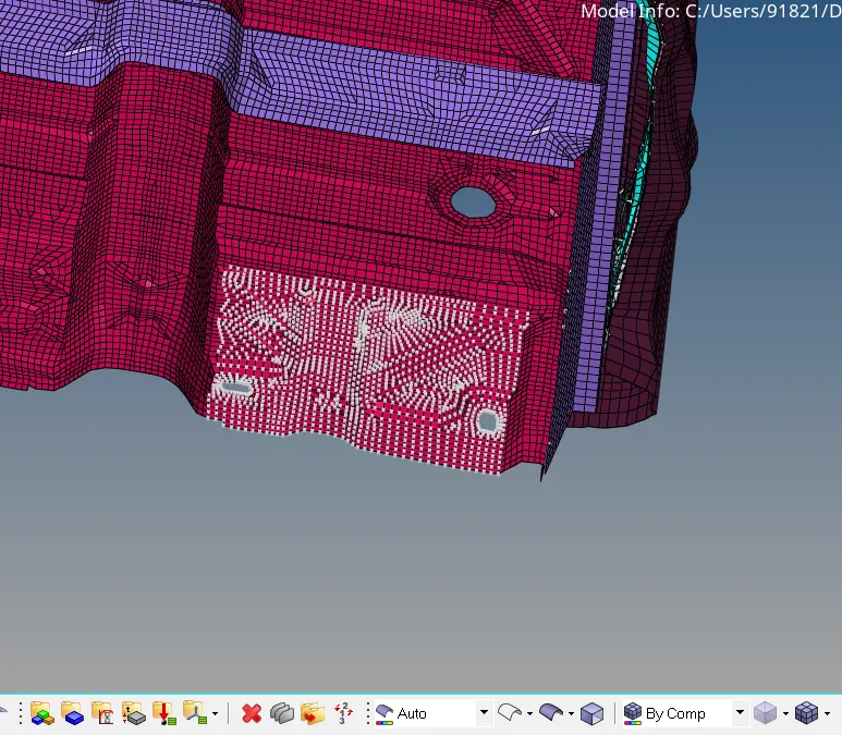
Adding mass to the Floor
Here we have to distibute the mass in such a way that our COG will lie at proper location and the overall weight should be we equal to 700 kg
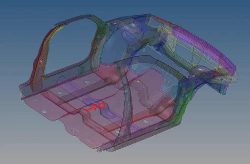
New posistion of COG with overall weight = 700 kg
- Initial velocity 35mph
Now we have to create the initial velocity in the Hypermesh, for that go to Solver >> create Boundary condition >> INVEL, in order to move car towards rigid wall we are defining the initial velocity to it, we have given initial velocity of 35mph, but we have to convert it into the mm/ms which is equal to 15.64 m/s or 15.6 mm/ms.
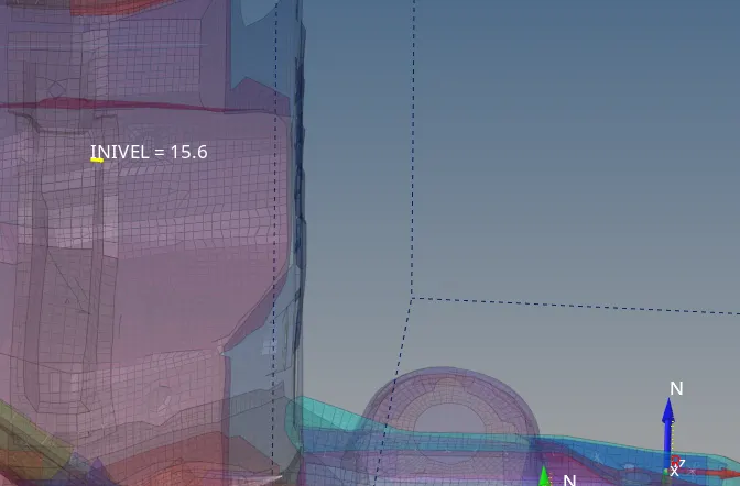
Defining Initial velocity
- Time step: 0.5 to 0.1ms
Input run time is 80ms that is the final time for run in the engine card ENG_RUN , Time step defaults for all element which is 0.003ms (Solver >> create >> DT) DT is the time step of simulation, Here to control the Time step ENG_DT_BRICK, ENG_DT_INTER, ENG_DT_NODA is already defined, with CST option which is constant time step during simulation by adding some mass.
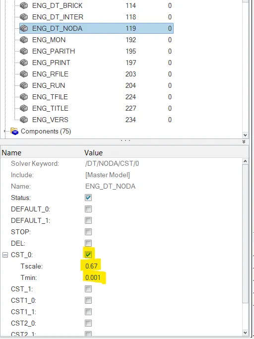
ENG_DT_NODA is defined
- Setup the model checker to see the error
Before creating animation it is always a best practice to eliminate error to get accurate result or some time due to these erro animation files doen't created. so to run the model checker in Hypercrah go to HYPercrash >> Quality >> Model check >> Run
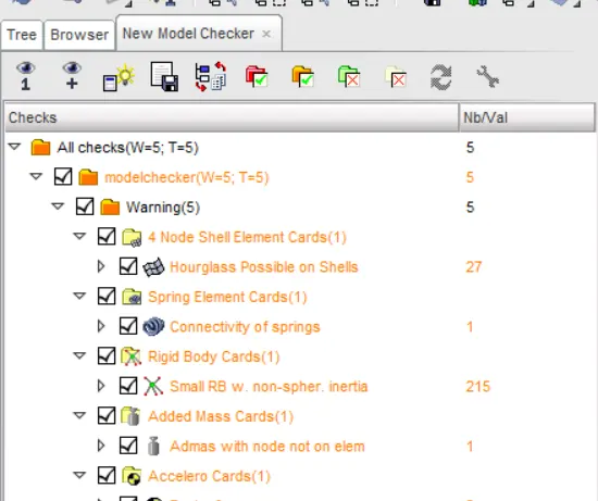
Here we have no errors but some warning found on Model checker, warning doesn't hurts a lot, but if you don't know about the issue behinds these warning, don't play with them otherwise it will ruin your result.
OUTPUT REQUEST
- Section force in the rails at location indicated node 174247
- Axial force recieved on the rails from the bumper.
- A-pillar cross-section.
- Accerlation curved recieved on the accelerometer at base of B-pillar (on B pillar rocker).
- Intrusion on the Dashwall 110020, 110021
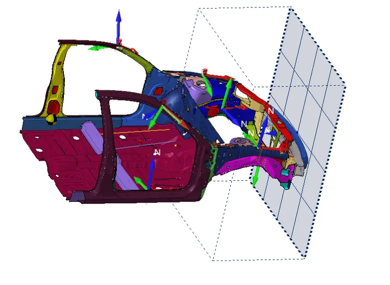
1. Section creation on rails, shotgun and A pillars cross-section, and on floor pillars near to accelerometer.
- To create section first we have to create the frames (Moving frames)
FRAME: Frame is type of reference co-ordinate system where the quantities defined follow its own origin. Here, unlike the moving skew, the moving frame is attached with the nodes which is selected as origin. calculates the motion of the body relative to frame defined. Frames are used only in notable option like imposed velocity, imposed displacement, TH/node etc.
To create frame go to solver >> Frame >> Mov frame
define the origin node and then define the z axis with second node which is in the direction of crash and the define the third node for plane.
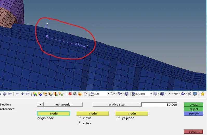
Defining a nodes to create frame
- After creating the frame, now we can create the Sections arroud the parts so that we can know the forces recived by that section. So to create the section go to Solver Browser >> Create >> SECT, here we have to define the frame and also we have to define the nodes and elements to create a section.
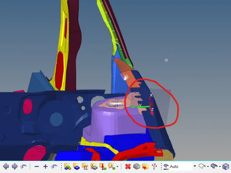
Creating a section on Right side Shotgun
- In similar way we can create the section for other part as well.
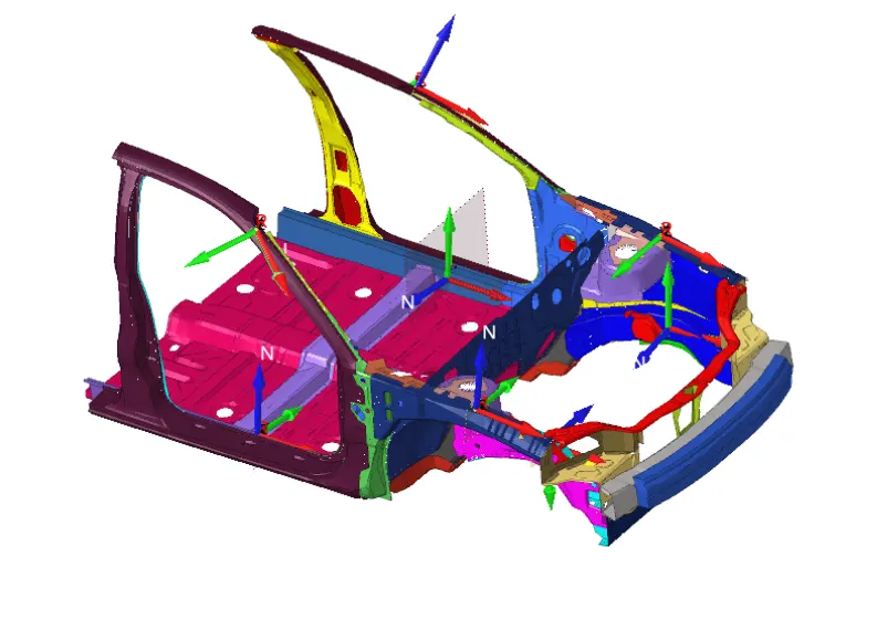
Creating an Section for all the required parts like Rails, Shotgun, A-Pillar...
- Creating an Accelerometer
To getting Accerlation curve or value near the B-Pillar rocker, we required accelerometer over there, so to create an accelerometer go to Solver >> ACEL, select node where we have to define the accelerometer. After defining accelerometer we required a sensor that note the value of accelerometer, so we have to create that Sensor to measure Accelerometer (ACCE). To create that go to Solver Browser >> Create >> ACCE, Here we have to put the accelerometer type 1, and NAC(Number of accelerometer) = 2, because we have to define to accelerometer on both side.
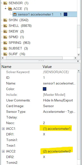
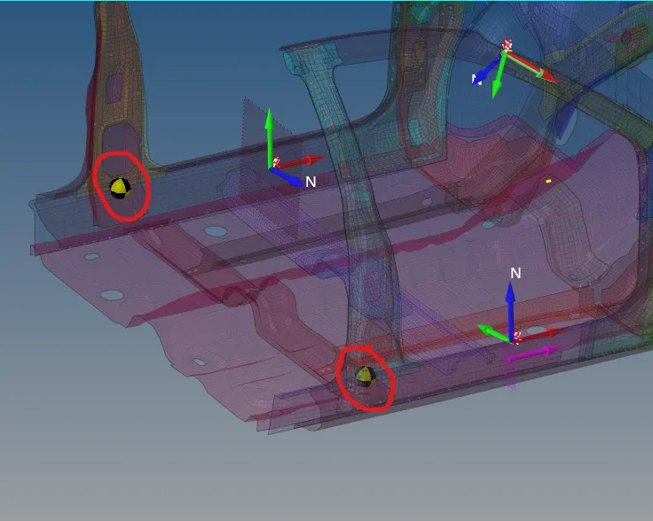
Creating an Accelerometer at B-Pillar rocker
- Now we have to be measure Intrusion on the Dashwall 110020, 110021
To measure intrusion on the Dashwall, we create the spring among the nodes and then do calculation that how much spring displaced, this is equal to the intrusion of Dashwall, kindly make sure that spring weight should be very small and also stiffness of spring also need to takne small.
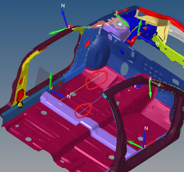
Creating 2 Nodes spring to measure Intrusion on Dashwall
- After definig all of those things, our job is not yet done, we need to extract the results from the Sections, Accelerometer and Springs.
Here we have to define the output blocks, Here in the output block there is previously created Blocks, we dont need that so we delete it,
Now to define the section in output block, create the new output block and define the the Entity id by cross-section and then select all the Sections that wre are created, and then click ok to define it.
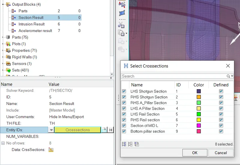
Creating Output block for Sections
In similar way we have to define the Output block for Intrusion and Accelerometer
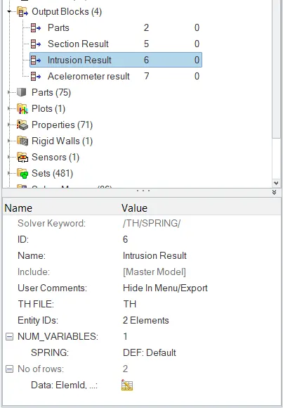
Defining an Output block for Intusion
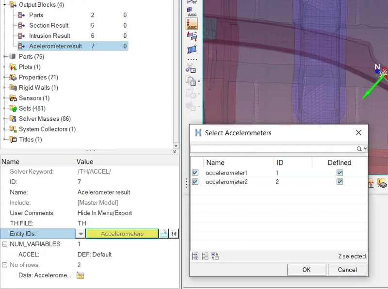
Defining a output Block for Accelerometers
- We also need to define Output Block for R-Wall.
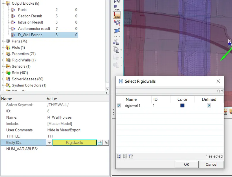
Defining an Output block for Rigid-wall
- Again we can check whether there is any error present in the model or not, for that we can either use Model checker or either we can do a Dry run, by setting the Stop time to 0ms, Here by this there is no generation of any Animation and Time history file.
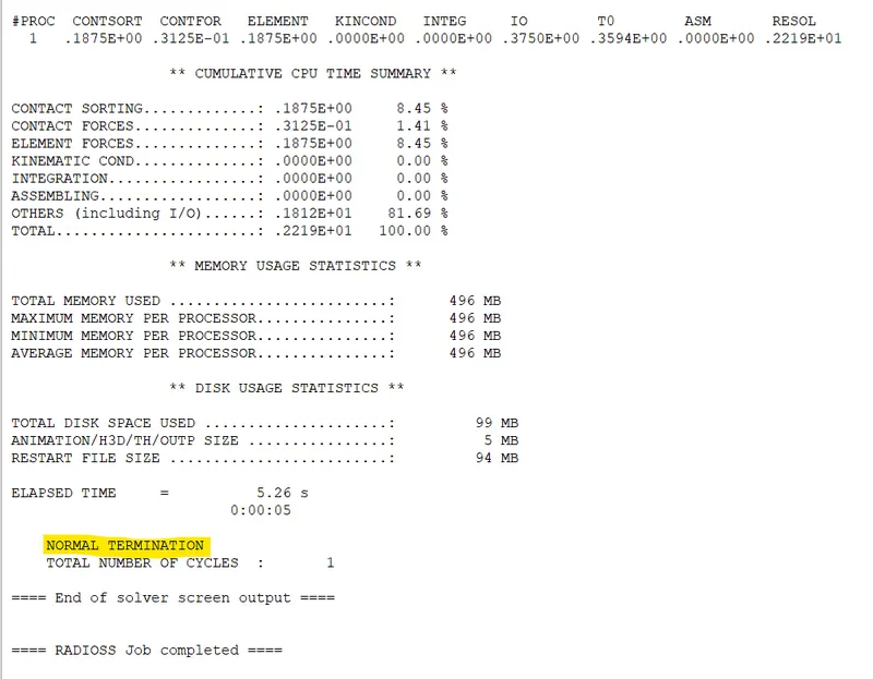
DRY-RUN
- After a Dry run we got 0 Errors, but it shows us some warning, we can neglect that warning, also it shows us Normal Termination at the end of the Simulation which indicates that our simulation is run without any error.
- Now we can run the simulation, for that go to Analysis panel >> RADIOSS >> select the input file >> save it in different folder and name it >> Run, also setting the -nt 3, whereas nt is number of threads or number of cores used to solve the problem is 3.
- After completing the simulation, the RADIOSS will popup a solver window stating RADIOSS job completed, which indicates simulation has been finished, also showing the total number of cycle and Elapsed time, means time required to solve the problem.
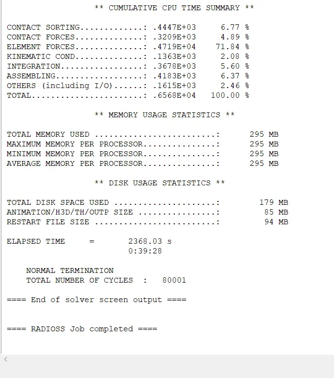
- Now we can run the simulation, for that go to Analysis panel >> RADIOSS >> select the input file >> save it in different folder and name it >> Run, also setting the -nt 3, whereas nt is number of threads or number of cores used to solve the problem is 3.
- After completing the simulation, the RADIOSS will popup a solver window stating RADIOSS job completed, which indicates simulation has been finished, also showing the total number of cycle and Elapsed time, means time required to solve the problem.
End of solver Output
To check the value of Energy error and Mass error, open the 0001.out file in Note pad
Energy Error:
- If energy error is negative, it means some energy is dissipated. This dissipation can be of any type for example in case of under-integrated elements, the Hourglass energy can explain a negative energy error since it is not counted in the energy balance. The acceptable amount of Hourglass energy is about 10-15%
- If energy error is positive there is energy creation. In case of QEPH elements the solution is calculated accurately as there is no hourglass energy is produced. A positive energy error of 1-2% is acceptable.
- If energy error is -99% the computation has diverged, this happen due to false energy balance that is created due to improper model definition.
Mass Error:
- Non Zero value of mass error is printed because of mass added to meet specific time step
Mass Balancing: Mass of whole model needs to be consistent throughout the model simulation. There shouldn't be any change in the mass, we need to be carefull and and need to checked where it will be coming from, when we try to control the time step we allow some certain type of mass addition, If we added mass then mass is going to increase, and make sure that mass variation should be smaller than 1%.
If mass variation is b/w 1 to 3%, yu have to check if nodes with added mass are moving or not. if this is the case then added mass will result in increase in kinetic energy. So for more than 3% of variation in mass results are probably bad.
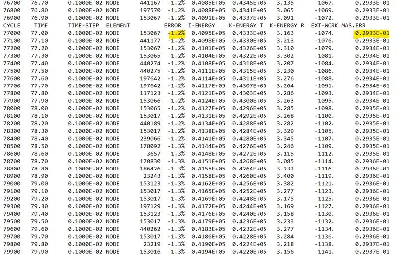
Both Energy error and Mass error is in acceptable range.
Mass error is occuring because of mass addition to make the Time-step constant.
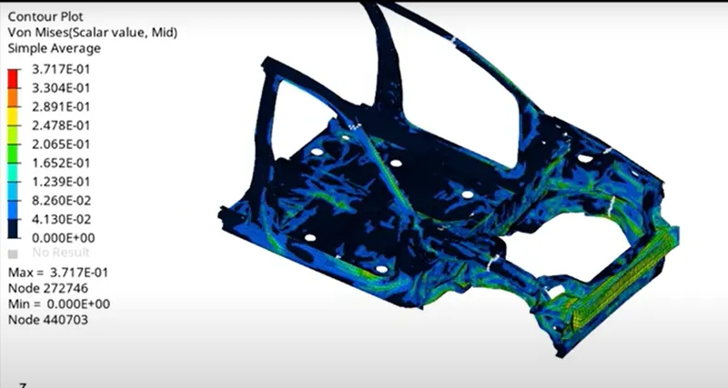
- After that we need to visualize it. For that we need to switch to the Hyper-view utility, in hyper-view we need to import the h3d file that was generated during solving. Now to display the result we need to select the result plot we required, here we check von-misses contour by selecting Global variable as Von-misses, and here we use averaging method as simple to visualize the result.
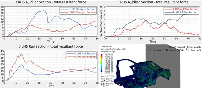
- To plot the graph, we need to switch to the Hypergraph 2D. we can switch to it using the same client selector option in toolbar, also in single window we can split it into number of windows, where we can plot the different plots. To plot the graph, we required the T01 file to upload to see the graphs. This file is available in same directory where we have .out files, h3d files, here we can plot different graphs like Rigid wall forces, Internal energy, Kinetic energy, Hourglass energy, Total energy to compare and visualize the result.
Graph 1.0 this shows the Internal energy / Kinetic energy / Hourglass energy / contact energy / Total energy
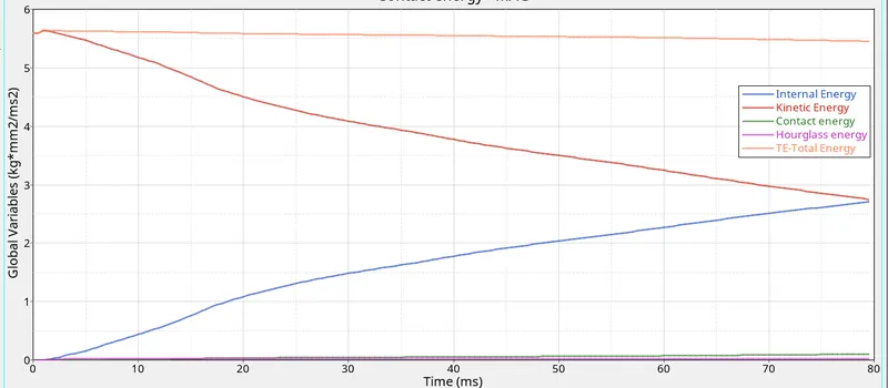
- Initially Internal energy is Zero, as simulation time increases, it increases with time until the crash complete, as you see here the Kinetic energy is high at initial, and decreasing with time, this is because kinetic energy is directly proprtional to velocity, so kinetic energy is maximum at initial stage, and with time Kinetic energy is lossed because the energy is absorbed during deformation, and this is nothing but the internal energy (du = q /w), which is increasing with time as the deformation goes on increasing, and it stop increasing when the deformation stops,(Kinetic energy becomes 0).
- Total Energy = Internal energy + Kinetic energy + External work, Here Total energy is not depending upon external work because there is no any force actiong on the car BIW , only the car is moving with the initial velocity, with time Internal energy increasing, and kinetic energy is decreasing in same path, so the Total energy remains almost constant, there is small decrease in TE because of contact energy, which is nothing but energy acting opposite to system to prevent penetration acting on the system due to applied velocity.
Here both Hourglass energy and Contact energy is less than 15% of Total energy, which is good. So Here we want that structure need to absorb energy, and from the graph it is clear that almost all the energy is absorbed by structure, but here the structure deforemd a lot and we see some intrusion toward the passenger cabin. so we want there is prograssive deformation in the structure so that it can absorb energy during crash, and provide a cushning effect to the Passengers inside the car, so that they can't injured. So if you increase the structural stiffness of your car then it leads to higher deceleration of car which leads to chest injury, so it is not high speed that kills, it is due to sudden stopage of the car, so thats why we want the car structure could crumple and absorb the enrgy during crash, so the less energy is transmitted into passenger cabin which leads to several fatal injuries.
RIGID WALL FORCES:
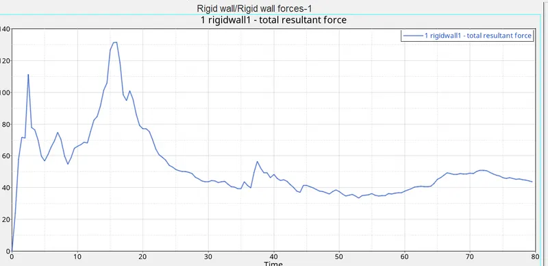
Rigid wall Forces
Rigid wall forces is peak at 16ms, there is rise and fall in graph is because of deformation of the structure, at 16ms structure has exhausted its deformable capabilities, after that forces are transfered to other region of BIW, due to this you see a fall in the curve, it also due to with time velocity is decreasing, because here we only apply the initial velocity not the imposed velocity, so due to this reaction forces are decreasing with time.
- Axial force acting on the Bracket
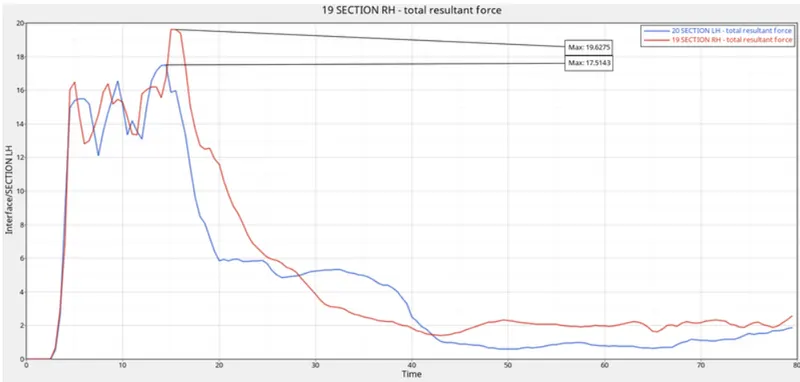
- The maximum force on the LH side is 17.61 KN and on RH side is 19.6 KN at 17 ms
- Shotgun sectional Forces
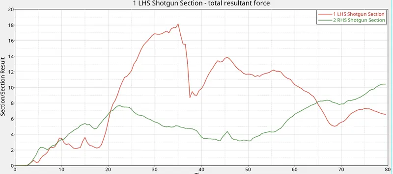
LH side shotgun at time = 35ms, Total resultant force = 18.11KN
RH side shotgun at time = 79.5 ms Total resultant force = 10.43KN
- A-Pillar and B-Pillar Sectional forces
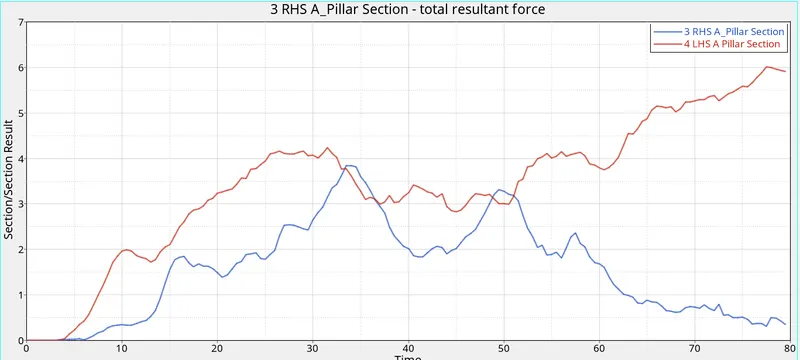
LH Side Pillar at time = 77.5ms Total resultant force = 6.01KN
RH side Pillar at time = 33.8ms Total resultant force = 3.836KN
- Frontal Rail Sectional Forces
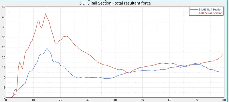
RH Side Rail at 14.5ms Total resultant force = 40.86KN
LH Side Rail at 15ms Total Resultant force = 24.21KN
- Sectional forces on Rocker
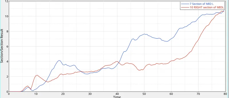
RH side of Rocker at time = 79.5ms Total resultant force = 10.77KN
- Accelerometer
An accelerometer is a device that measure the vibration, or accerlation of motion of structure. The forces caused by vibration or a change in motion (acceleration) causes the mass to sequeze the pizoelectric material which produces an electric charge that is proprtional to the force exerted upon it. we have mounted the meter on the rocker at a Base of pillar,
Why the accelerometer is set on their, this is because the output that recieved from the accelerometer is become input for the sledge test, so that's why we mounted the aceelerometer at the base of B pillar on Rocker to measure accerlation, deceleration of the structure.
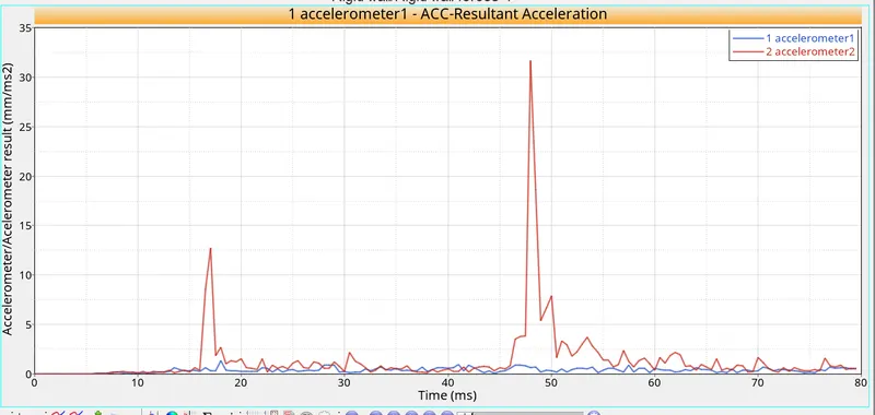
LH side (Accelerometer 2) at time = 45ms the the value of accerlation noted = 31.66 mm/ms2
- Intrusion on the Dashwall at 110020 and at 110021
Footwell intrusion describes a situation in which an automobile engine or other vehicle component penetrates the space normally allocated for the feet of the front seat occupants.
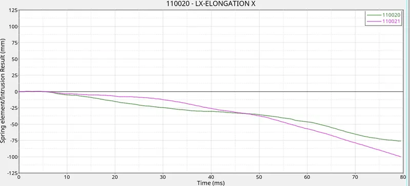
Maximum Intrusion on the Dash wall is 100 and 75 mm
Learning Outcomes:
Understanding about how
- To define INVEL for the model.
- To define Accelerometer for the model and why we need to define it.
- To adjust the mass balance to get the desired COG location.
- To create moving Frames and why they are created
- To create skews in the model
- To create the sections to obtain results
- To use Model checker and Dry run to check error
- To provide the output result in the output blocks.
CONCLUSION:
Hence by performing this project, we conclude that during crash analysis the lot of forces and energy is absorbed by structure by crumpling or deforming , but there is small intrusion in the passenger cabin that may leads to cause injury to the passengers, and also at COG BIW structure is going to bend, but overall we can say that this structure is capable of absorbing energy during crash.