Assignment 6-Frontal Crash Simulation Challenge
Aim:
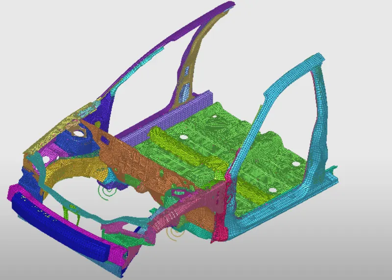
To perform Crash test for Car frontal BIW structure using Hypermesh and Radioss.
Objective:
Frontal crash-BIW
- Check unit system and either follow[Mg mm s] or [Kg mm ms).
- Create appropriate interface ,friction O.2 and recommended parameters.
- Make sure of no penetrations and intersection. • Correct rigid bodies if any issues.
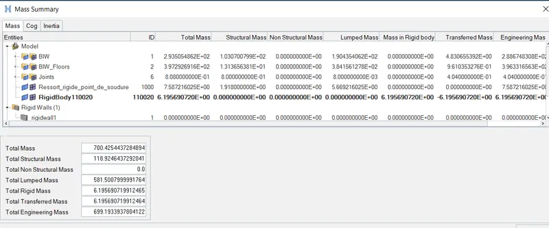
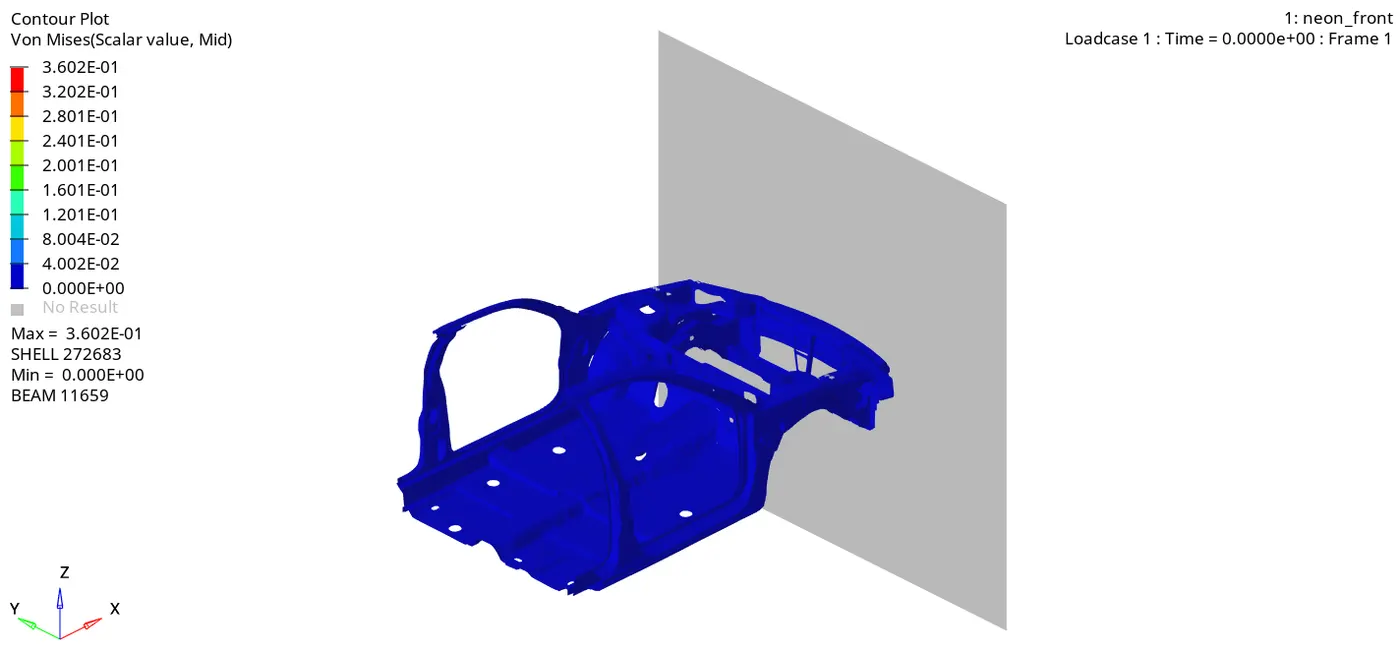
- Create rigid wall with friction 0.1. Compare the model weight with the full scale 300k nodes model and use added masses to reach target weight 700kg while getting CG about the required range.
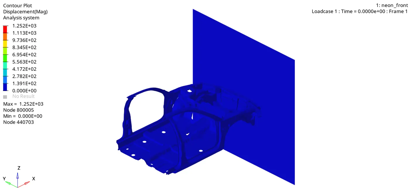
- Initial velocity 35 mph.
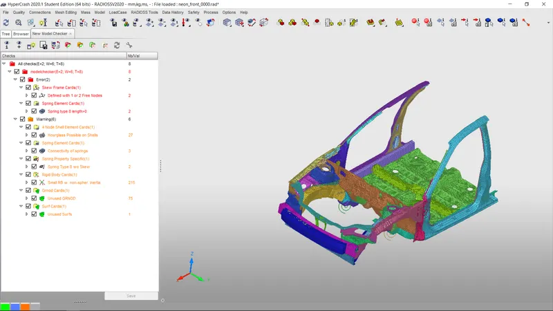
- Use model checker to ensure good quality. Time-step :0.5 to 0.1 microseconds.
- Run 80 ms.
Output requests:
- Sectional force in the rails at location of indicated node 174247.
- Axial force received on the rails from bumper. Shotgun cross sectional forces.
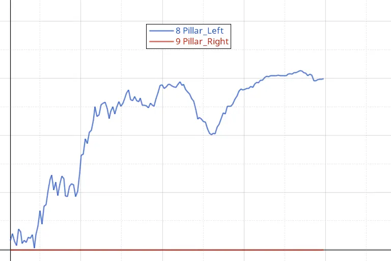
- A pillar cross sectional forces.
- Acceleration curve received on the accelerometer at base of B pillar (on B pillar rocker).
- Intrusions on the dash wall 66695,66244. Procedure: Check unit system and either follow[Mg mm s] or [Kg mm ms]:
- To check the units one can use any of the following procedure.
Procedure:
Check unit system and either follow [Kg mm ms]
- By looking into the starter file: Open 000.rad file, at the begining the units will be displayed.
- In hypermesh: Open the 000.rad file in hypermesh, navigate to model browser and then in cards there will be a begin card. By clicking on the card units will be displayed.
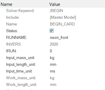
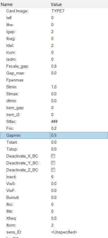
Create appropriate interface ,friction O.2 and recommended parameters:
- To create the interafce, go to solver browser >> right click and select inter >> type 7.
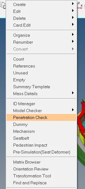
Checking for Penetrations and Intesections:
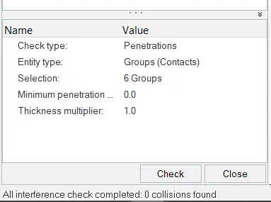
- After providing the interface, we need to check for penetrations. To check this, go to Tools >> Penetration check >> select the group >> check.
- There are no penetrations and intersections are found. So we can move onto the next step.
Create rigid wall with friction 0.1:
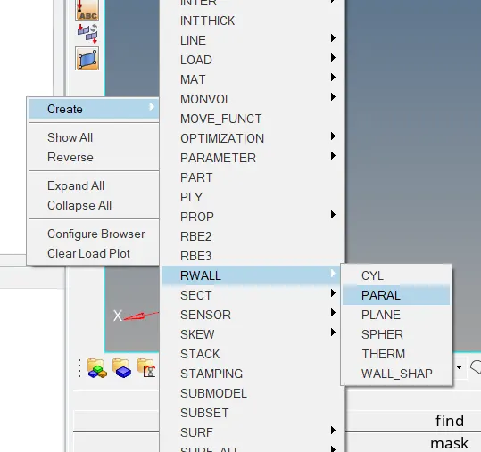
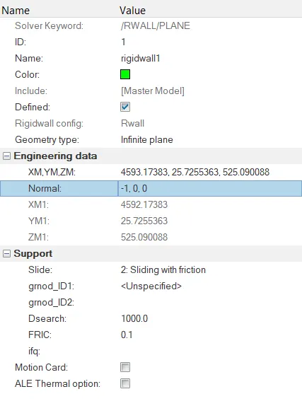
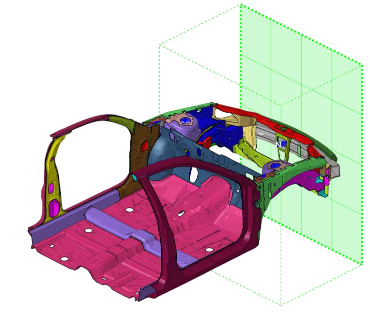
- To create a Rigid wall, go to solver browser >> right click » Plane. Give the appropriate X,Y and Z and select Rwall : coo-ordinates, friction as O.2 and Search distance as 1000 to create the Rigid wall.
Adding masses to reach target weight 700kg while getting CG about the required range:
- To check the mass and COG, go to tools >> mass details >> mass, cog and inertia. Now by clicking on the COG we can get the co-ordinates of the COG. Create a node using the co-ordinate values.
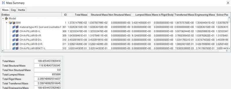
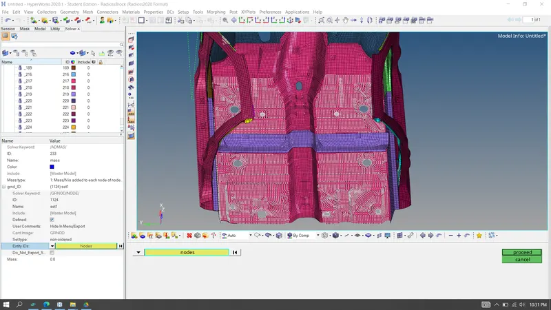
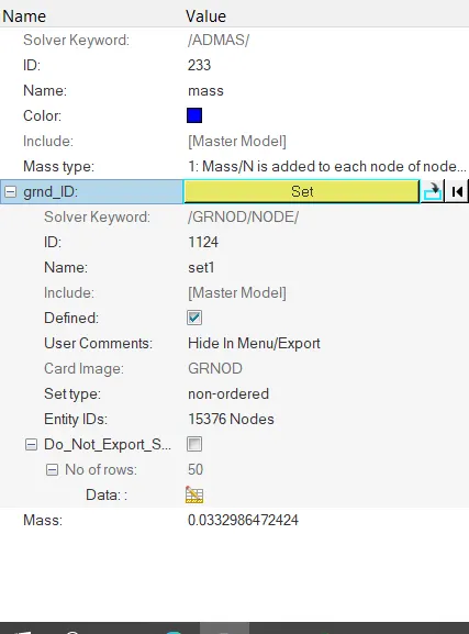
• The COG is not at the correct location, so to change the COG to the correct location mass need to be added. To add mass, right click in the solver browser >> create >> admass > right click on grnode >> select the nodes >> assign the mass
Assigning Initial velocity 35 mph:
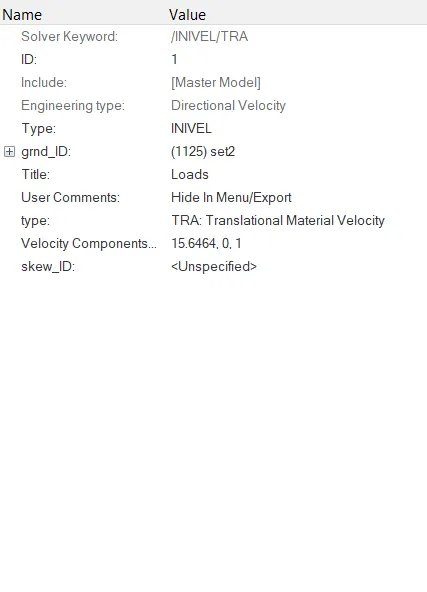
• To assign Initial velocity to the model, right click in solver browser >» boundary conditions » Invel
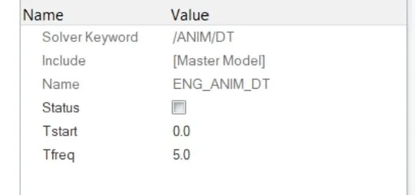
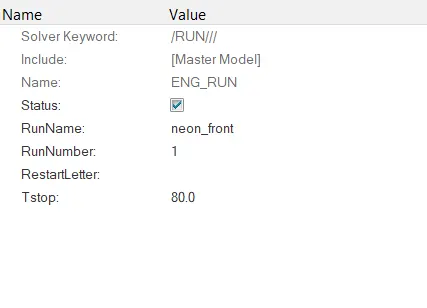
Assigning Time-step to 0.5 ms and run to 80ms.
- To assign the time step, go to model browser >> cards >> ENG_AMIT_DT > Tfreq = 5.
- To assign the run time, go to model browser >> cards > ENG_RUN > Tstop = 80.
Output requests:
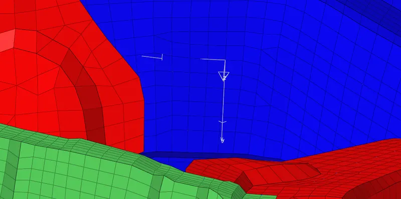
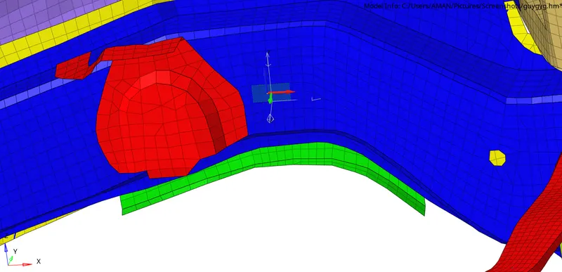
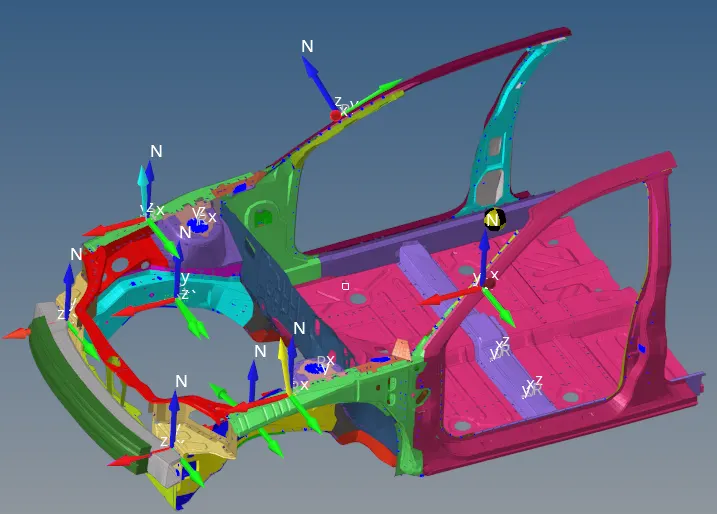
Before creating a section, a frame should be created at the indicated node and the frame is assigned to the section. To create a frame, right click in solver browser >> create >> frame >> MOV >> select the origin >> x-axis >> xy plane >> create. After creating the frame, section can be created.
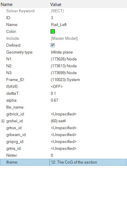
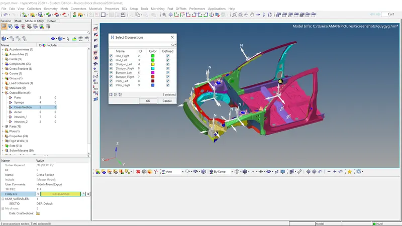
- Sectional force at a node 174247: To create a section, right click in solver browser >> create >> SECT >> SECT. The N1, N2 and N3 values should be equal the origin, x-axis and xy plane nodes of the frame and remaining properties are assigned as shown in the figure below.
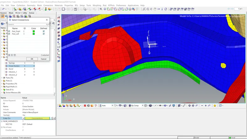
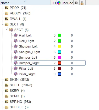
Similarly frame and section are created for all across section
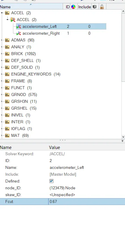
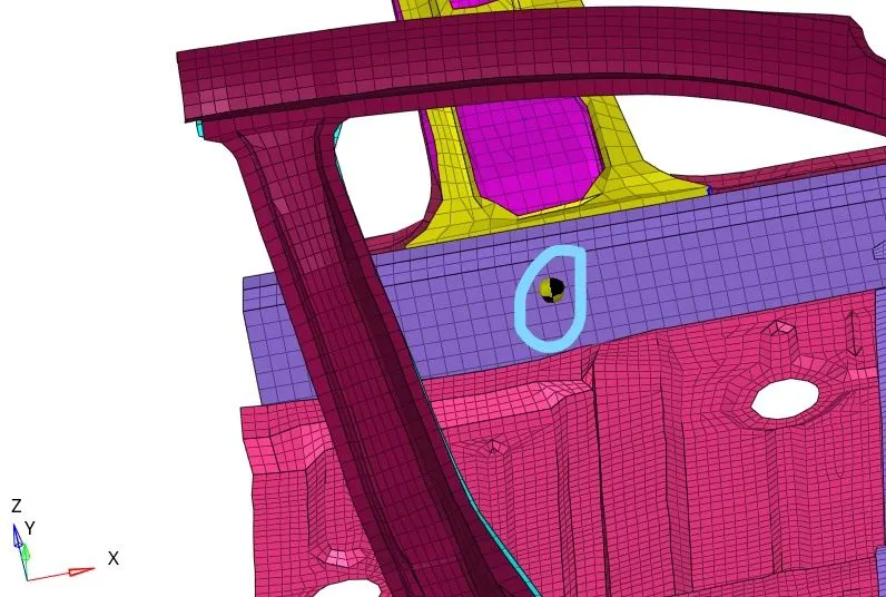
• Accelerometer at base of B pillars (on B pillar rocker): To create an accelerometer, right click in solver browser > create >> ACCEL > select the node >» fcut = 1.65
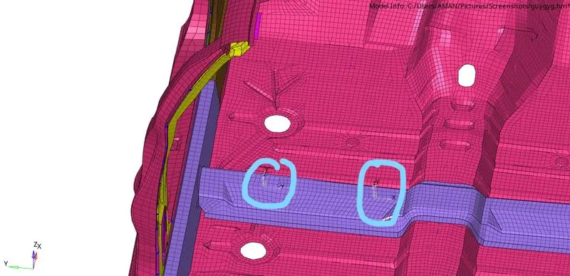
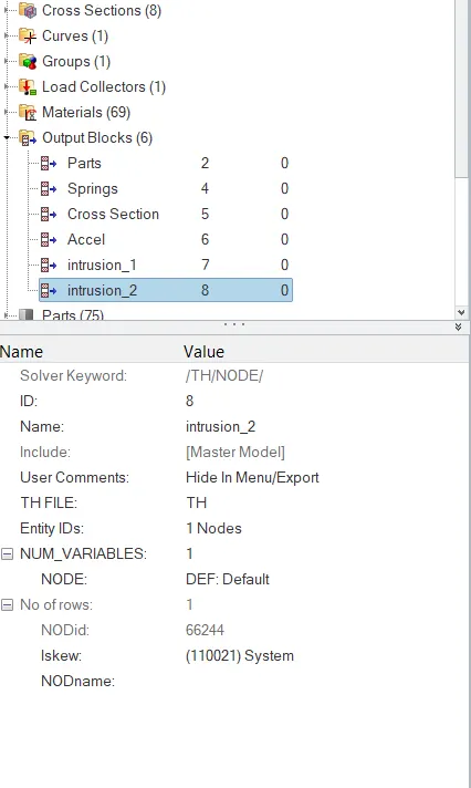
- Intrusion on dash wall at nodes (66695, 66244):Intrusion is created on the dash wall to check the displacement occured due to collosion. To create an intrusion, right click on solver browser >> TH >> NODE >> select the node >> create the skew by right clicking on it.
- Now the model is ready to run the simulation. To run the simulation, go to analysis >> radioss > select the path to save the files >> radioss.
Results and discussion:
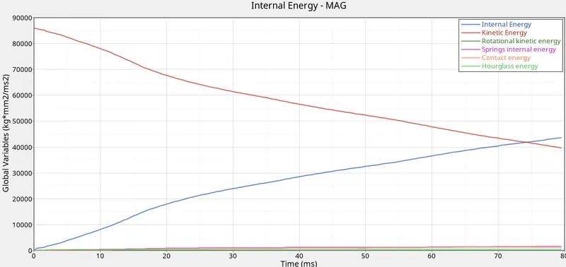
- Now open the 000.out file to check the energy and mass error. The energy error should be in between -15% to 5% and mass error should be in between O% to 5%.
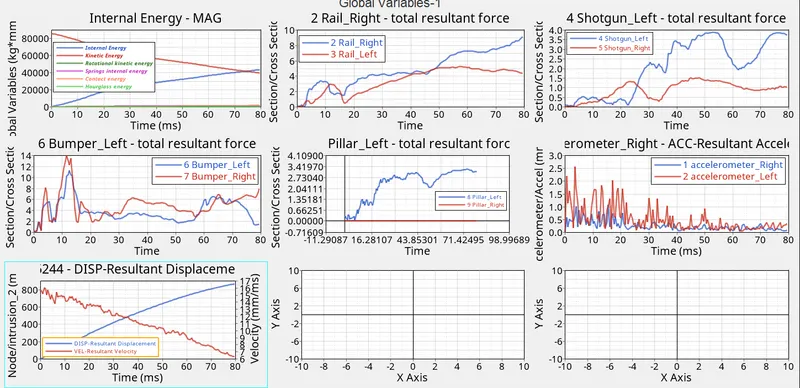
- Now open the Hypergraph and open the TO1 file to check the forces vs time graphs.
Energy graph:
In Rails:
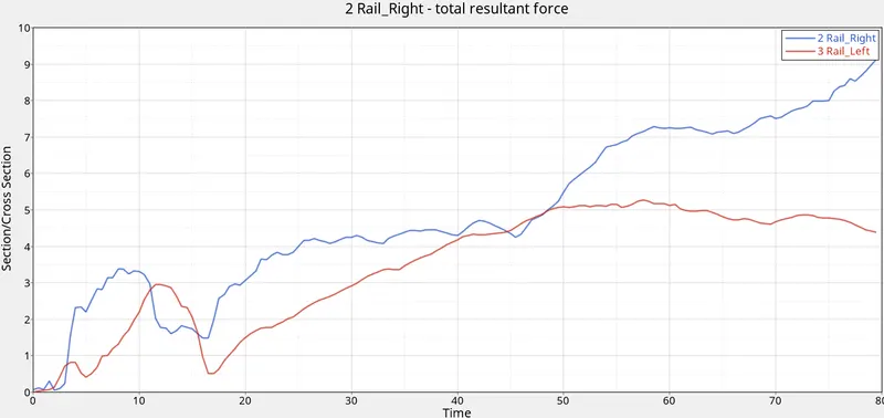
- Maximum forces in the rails is 9.2KN
In Shotgun:
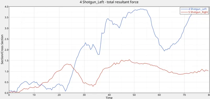
- Maximum forces in the shotgun is 3.8KN
In Bumper:
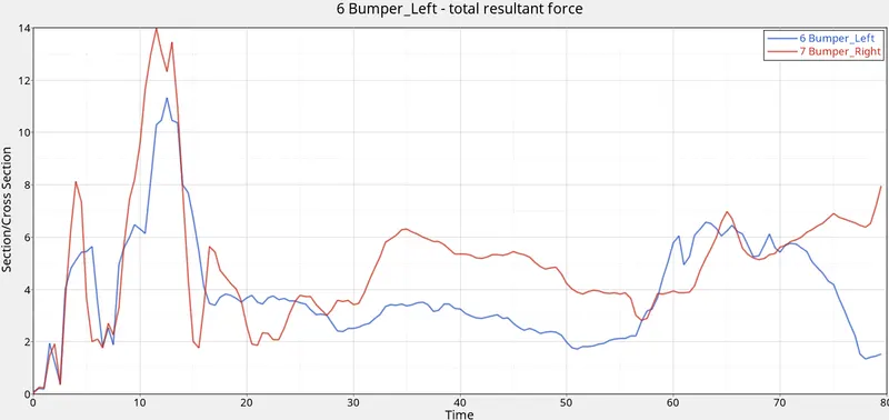
- Maximum forces in the bumper is 14KN
In Pillar
In Acceleration
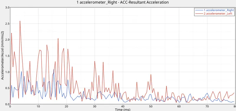
- Maximum acceleration achevied is 2.6 mm/ms
DRIVE
https://drive.google.com/file/d/1M4_yxNnSIQRuY3-Q2Bnt3nCMWmKdFkMM/view?usp=drivesdk