Assignment 6-Frontal Crash Simulation Challenge
- Objective: To perform Frontal crash analaysis on the given car model and plot the results at different cross sections responsible for taking and transmitting the forces after impact.
- Procedure:
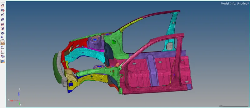
Import the given .0000 rad file into Hypermesh. Go to File > Import > Solver deck and import the file.
After importing the model, let us check the material properties to identify the unit system. Go to Model browser > Materials and click on any created material.
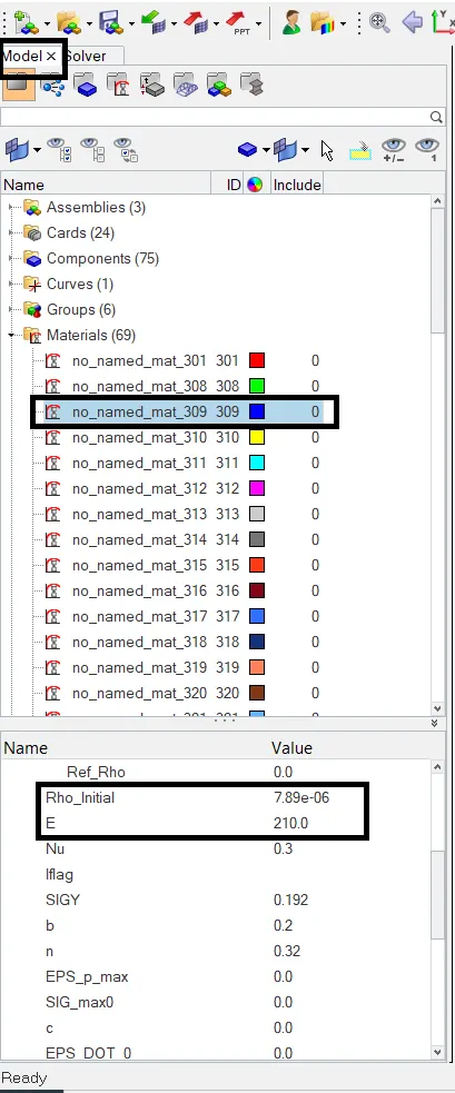
From the values of density and Young's modulus, it can be seen that these are the properties of steel and the unit system followed is Kg mm ms. We will follow this unit system to maintain unit consistency.
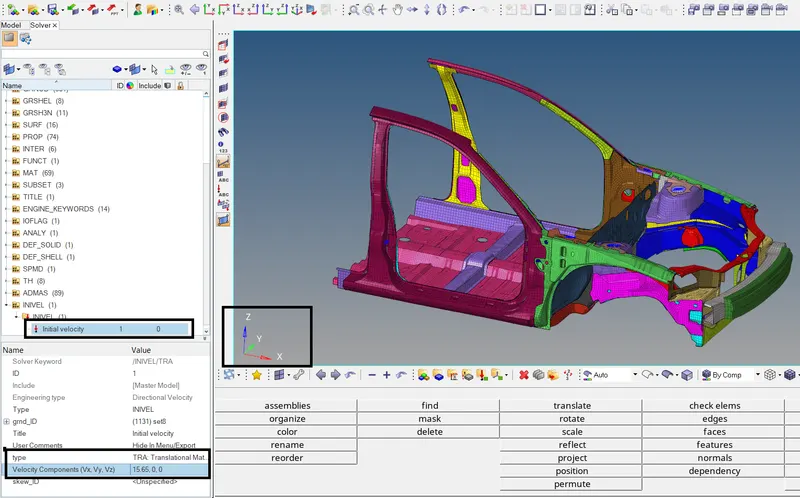
Now let's apply the initial velocity to the modal. Velocity of 35 mph is to be applied. Following the consistent units, we will apply the velocity of 15.65 m/s.
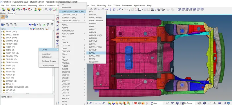
Go to Solver > Create > Boundary Conditions > INIVEL.
Go to grnd_ID and right click on it and hit Create.
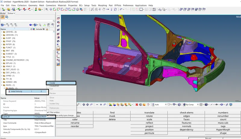
Set the entity selector to components and select all the components.
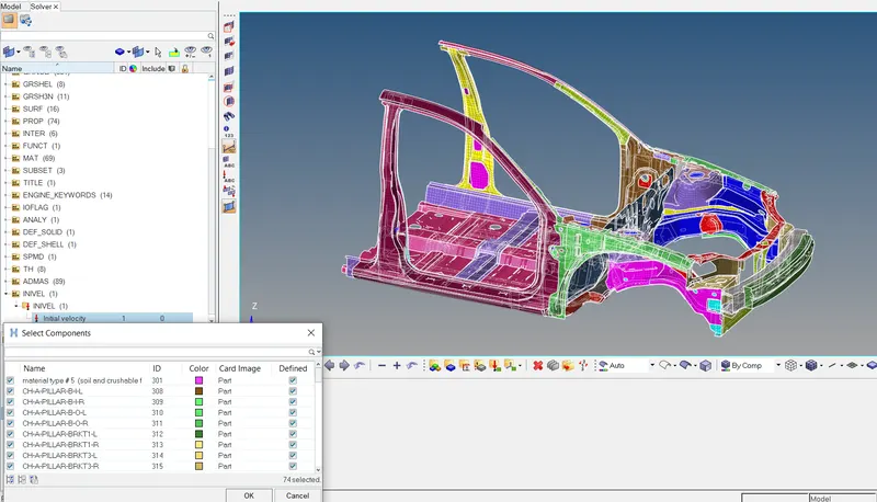
Select the type as TRA. In the velocity component, enter Vx = 15.65 since we want the velocity in the global X direction and Vy and Vz = 0.
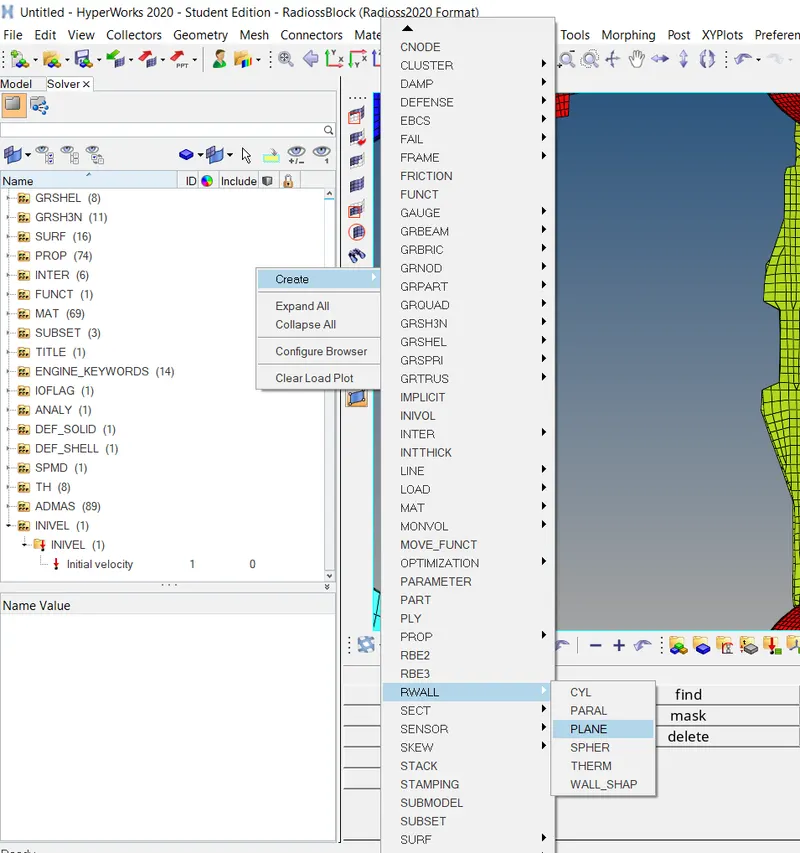
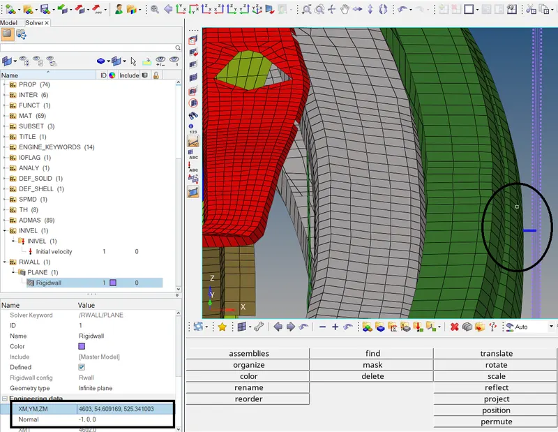
Now create the rigid wall. Go to Solver browser > Create > Rwall > Plane.
We will create the rigid wall passing through the outermost node on the bumper with normal in -X direction and then offset in further in X direction to maintain distance between the wall and the model. In the
XM, YM, ZM tab, click on the arrow button and select the displayed node and click on proceed.
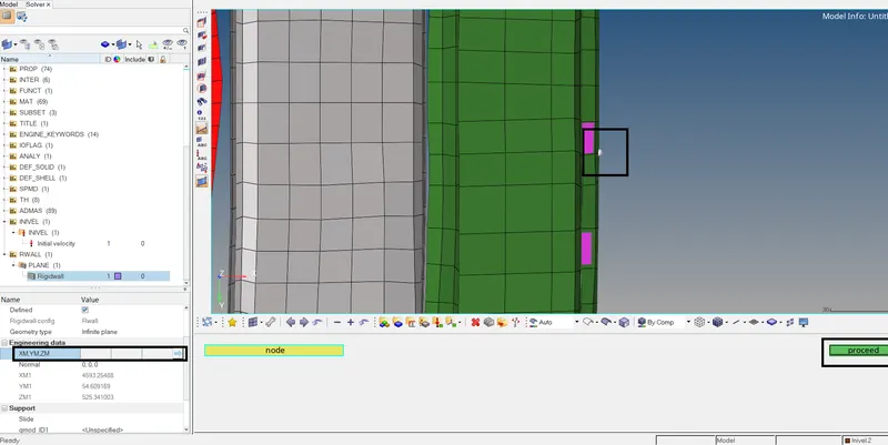
Increase the XM value to 4603 to move the rigid wall further by 10 mm and in the Normal tab, enter -1 for X as we want the normal of the wall in the negative X direction.
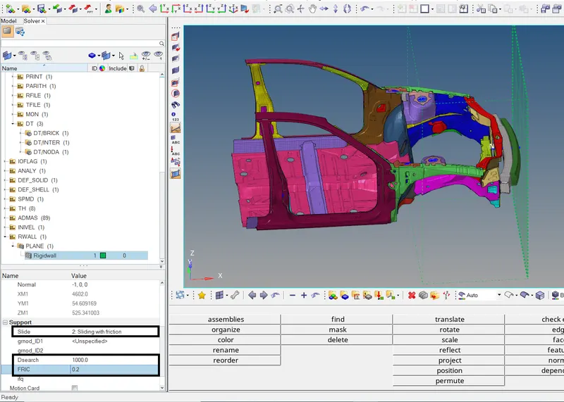
Under support tab, set the slide to option 2 and search tolerance as 1000 and friction value as 0.1.
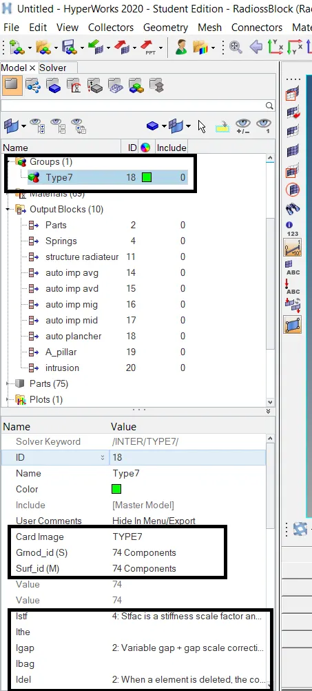
Create Type7 interface with friction 0.2 and recommended parameters. Go to Solver browser > create > INTER > TYPE7. In the grnod_id and the surf_id selector, select all the components for slave nodes and
master seg . Enter Istf = 4, Igap = 2, Idel =2, Fscale_gap = 0.8, Idel = 2, Stmin = 1, Fric = 0.2, Gapmin = 0.5 and Iform = 2 which are the recommended interface parameters.

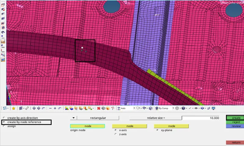
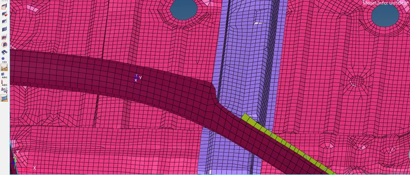
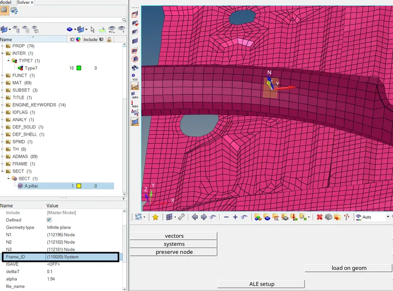
Now create cross section for A pillar. For that, we need to create moving frame first. Go to Solver browser > Create > Frame > Mov > create by node reference. Select the nodes displayed on the A pillar
to create the frame.
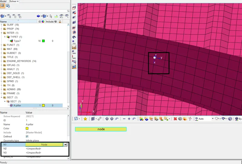
Now to create the c/s, go to Solver browser > Create > SECT > SECT and rename it to A pillar. In the N1, N2, N3 selector, select the same node which we selected during the creation of Frame and click on
Proceed. Enter deltaT and alpha = 0.1 and 1.94 respectively. Enter Iframe =12.
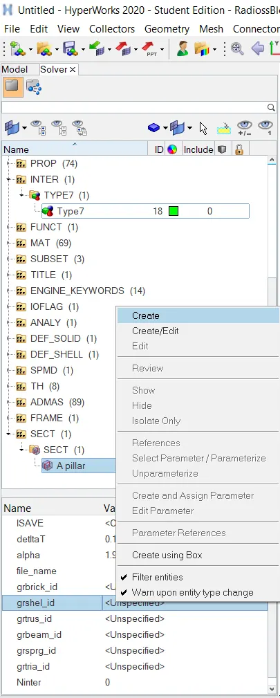
Right click on grshelid and click on Create.
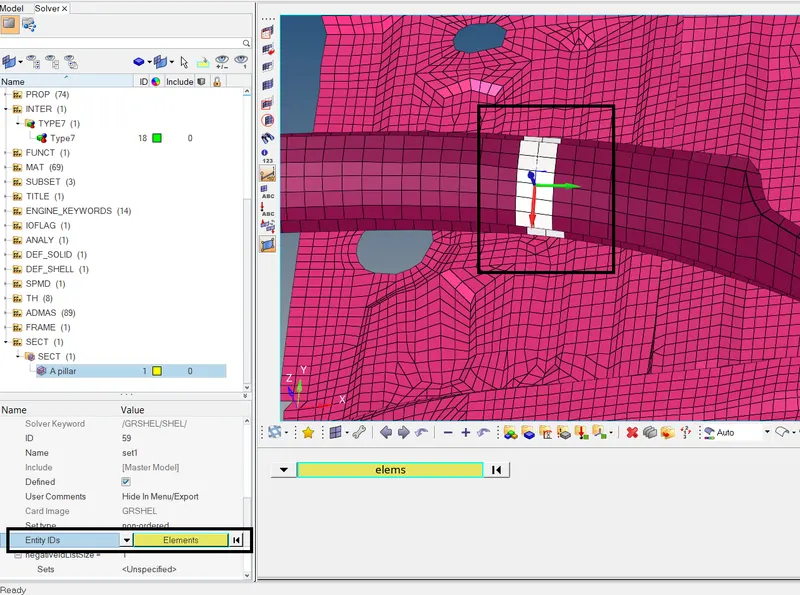
In the entity ID's selector, set the entity selector to Elements and select the displayed rows of elements and click on Proceed. In the Frame id Selector, select the frame which we had earlier created. The
cross section is now created.
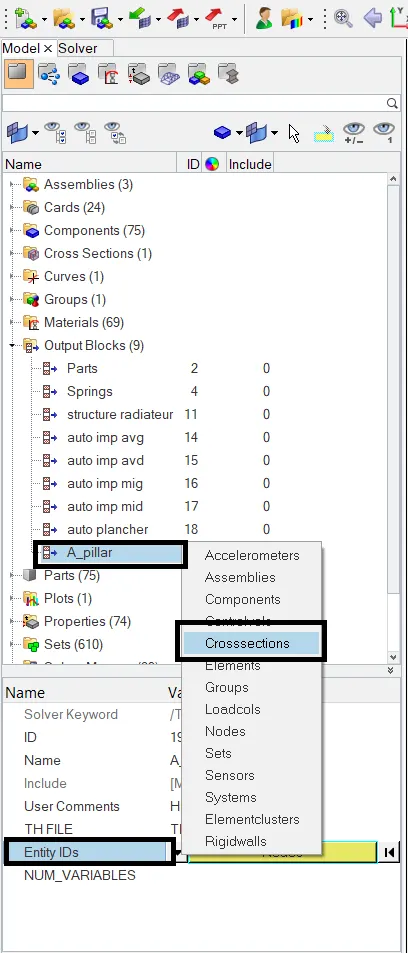
Once the c/s is created, we can request for output results at the cross section. Go to Model browser > Output Blocks > Create. Rename it to A_pillar. Set the Entity IDs to Crosssections.
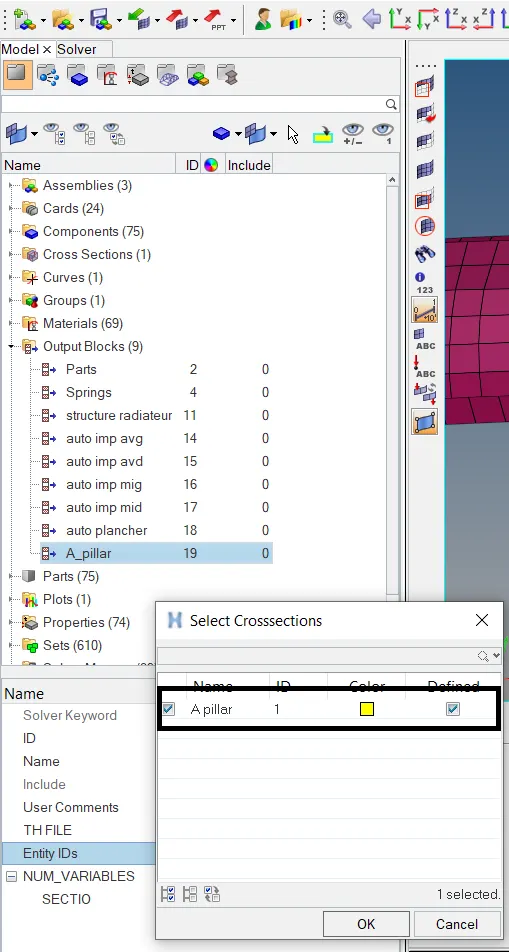
Select the A pillar c/s which we had created earlier.
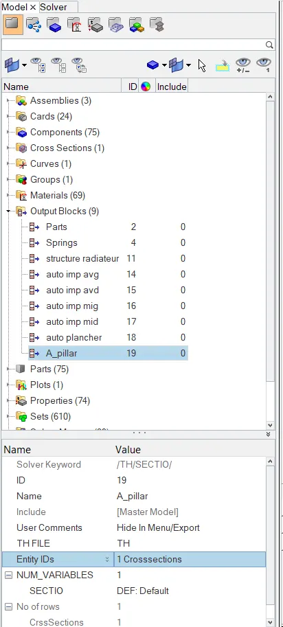
The output request at the cross section of A pillar is now created. Similarly create c/s and output requests for the bumper plate, shotgun and rails as these components are responsible for taking the most of
the forces and transferring it further after impact.
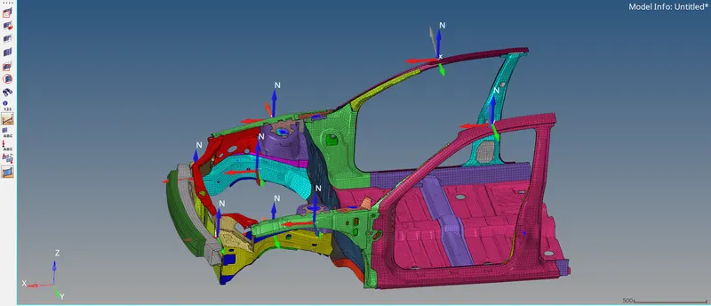
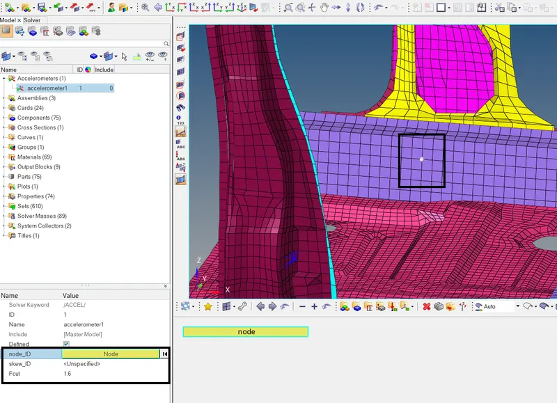
To create Accelerometer on the base of B pillar, go to Model browser > Create > Accelerometer. In the node_id selector, select the displayed node. Enter Fcut = 1.6. The accelerometer is created.
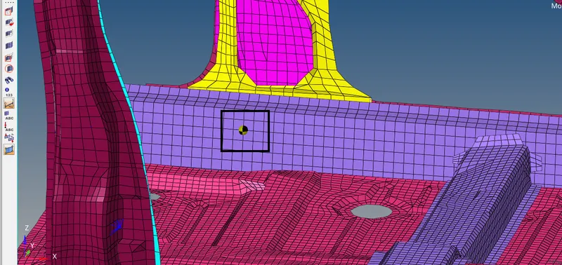
Right click on the Output block in the Model browser and click on Create. Rename it to Accelerometer.
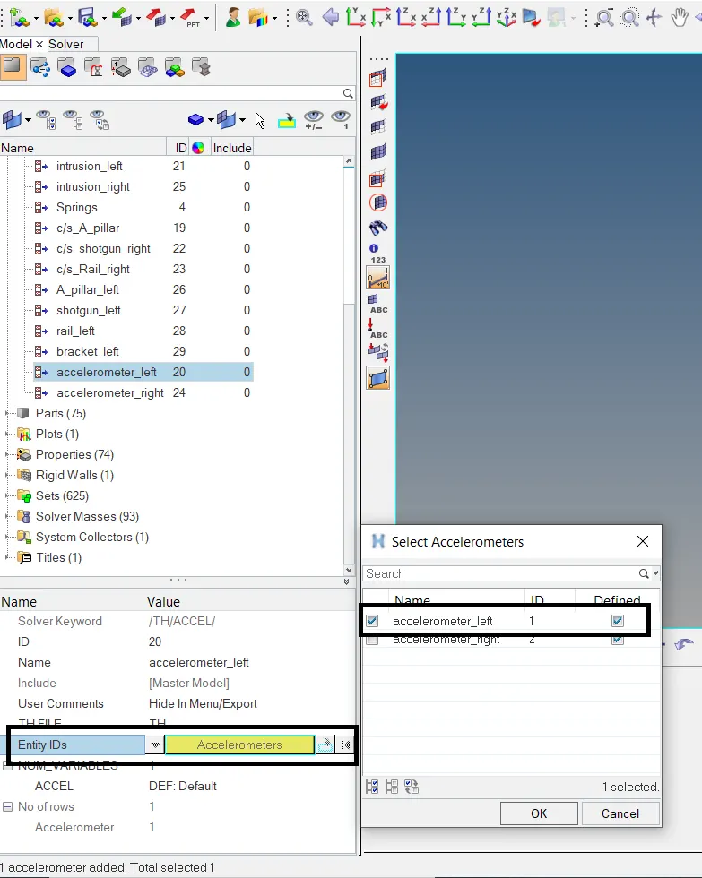
Set the Entity ID's selector to Accelerometers. Click on it and select the created accelerometer. The output request for accelerometer is completed. To request the output for intrusions on the dash wall, first
we need to create moving skew. Go to Solver Browser > Create > Skew > MOV > create by node reference. Select the displayed nodes on the croos beam and click on proceed. The moving frame will be
created.
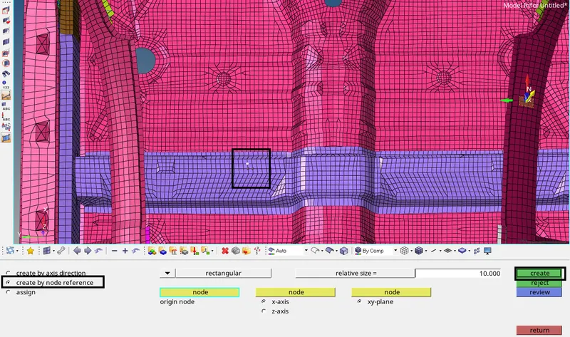
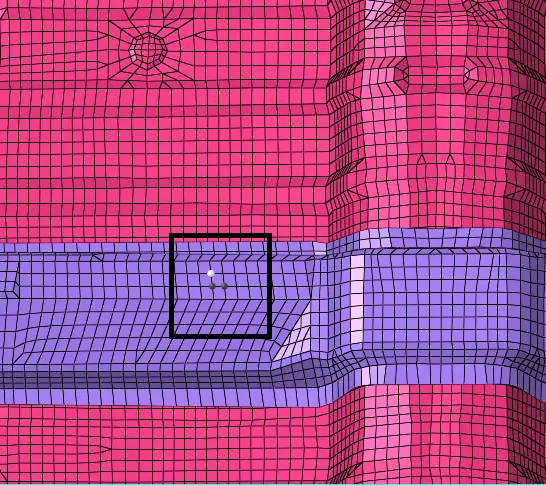
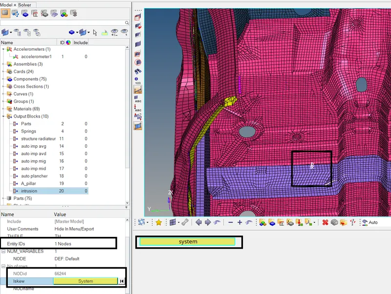
Now go to Output Block > Create. Rename it to intrusion. In the Entity Id's selector, set the entity slector to Nodes. Select the node with id 66244. In the Iframe selector, select the moving skew we just
created earlier. The output request is now completed.
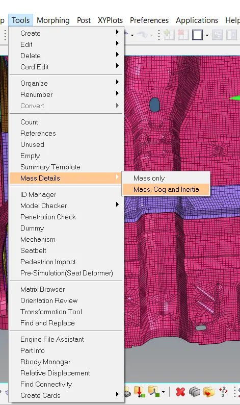
Now as per the requirement, the total mass of the reduced car model should be made equal to 700 kg just like the mass of a full scale model. To check the mass of the model, go to Tools > Mass Details >
Mass, inerita and cog > cog.
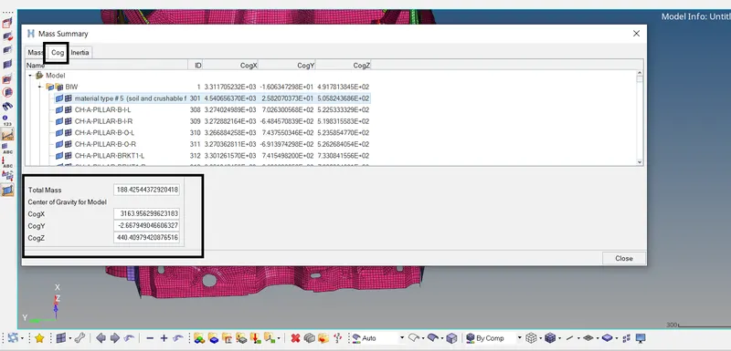
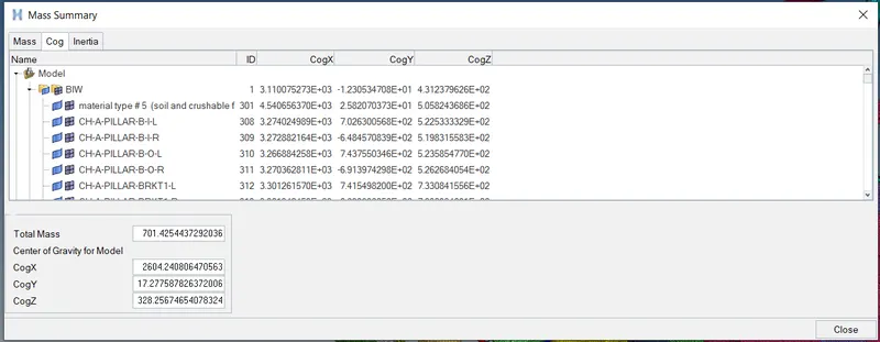
The total mass of the reduced car model is 188 Kg. Using the shown coordinates, we can create a node at these coordinates to find the location of cog. The cog lies near somewhere near the dash wall in the
centre. We need to shift the cg downwards on the cross beam. Using the additional mass of 512 kg which we have to add to achieve the target weight of 700 kg, we can shift the cog near the cross beam.
To add mass, go to Solver browser > Create > ADMAS. Set Mass type to 0 which will apply the entered value of mass to each selected entity. Right click on the grnd_ID and hit Create.
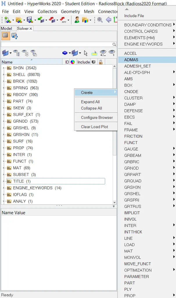
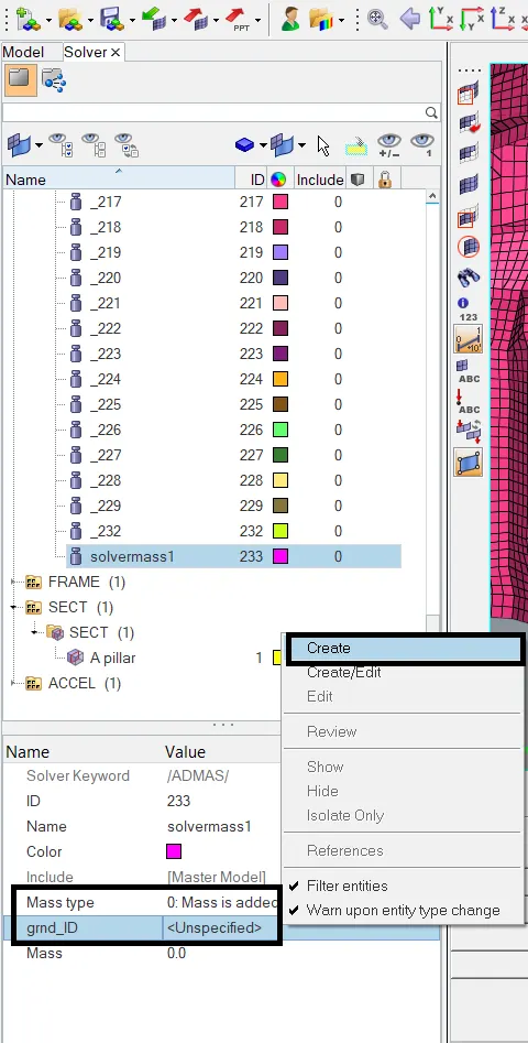
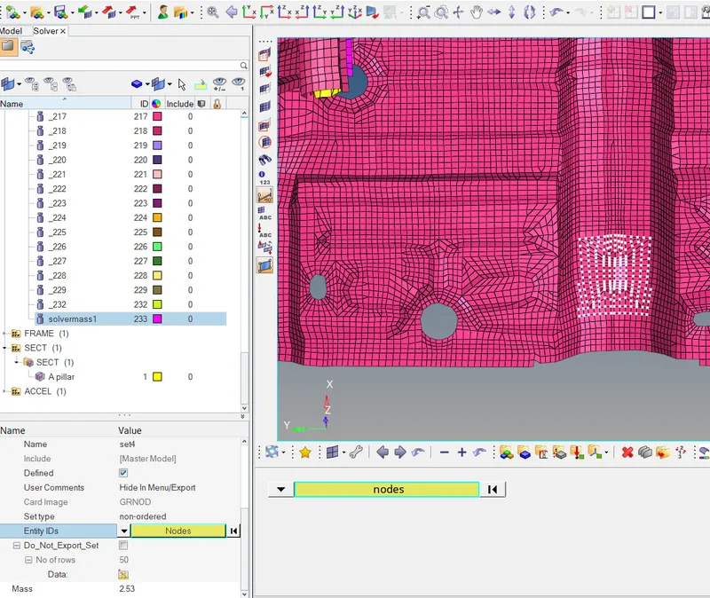
Set the Entity ID's selector to Nodes and select the displayed nodes at the end. Enter Mass = 2.53. 203 nodes are selected, so the total mass apllied will be 203 x 2.53 = 513 Kg. Click on Poceed. The mass is
now added.
Now again go to Tools > Mass Details > Mass, inertia, cog > cog. Check the total mass and the coordinates of cog. Total mass of the car model is now 701 Kg. To locate the cog, create a temporary node at the
coordinates seen below.
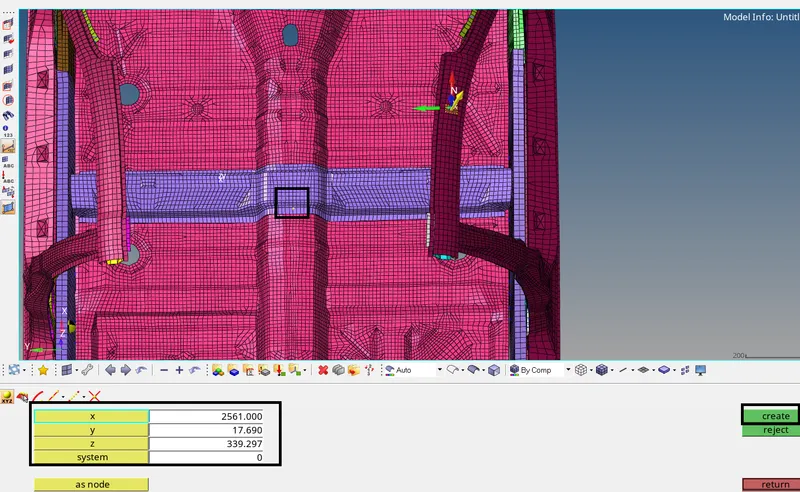
Go to Geom > nodes. Enter the coordinates and create the node. The node indicates the location of cog near the croos beam which is fine.
Now we can run the analysis. Before that, we need to check for any penetrations and run the model checker. The penetration check is performed in the Hypercrash.
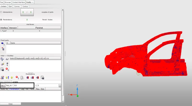
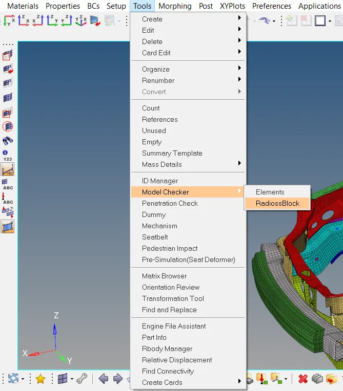
No penetrations or intersections are found. To run the model checker in Hypermesh, go to Tools > Model Checker > Radioss Block. Right click on Error and hit Run. No errors are found.
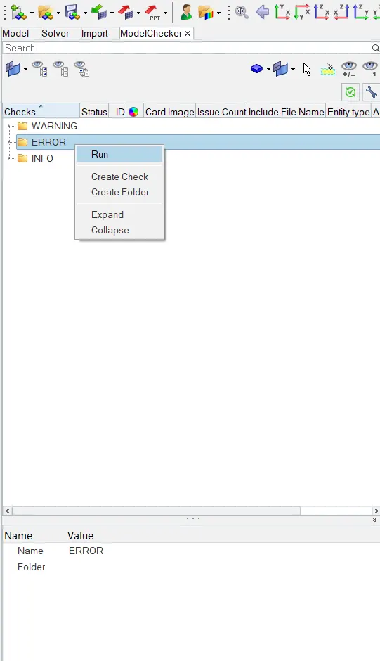
No errors are found. To run the analysis, go to Analysis > Radioss. Click on the save as option to define path to save the file. Click on include connectors. Click on Radioss. The simulation will start running.
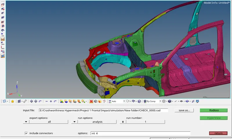
The simulation was completed with Normal Termination.
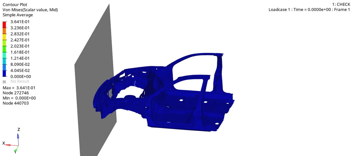
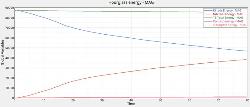
As seen above, the kinetic energy after impact starts decreasing with increase in the internal energy. As the car model deforms after impact there is increase in strain energy as indicated by internal energy.
There is no Hourglass effect observed. There is slight increase in the contact energy as seen. Contact energy is the energy used to remove penetrations. As contact energy slightly increases, a part of total
energy is used by the contact energy and hence a decrease in the total energy is observed.
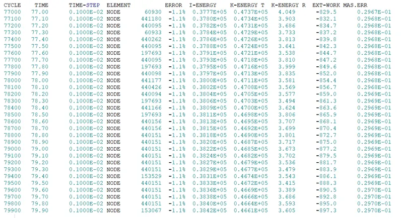
The energy error at the end of simulation was -1.1%. Mass error was 2.97 %. Both the errors are within acceptable range.
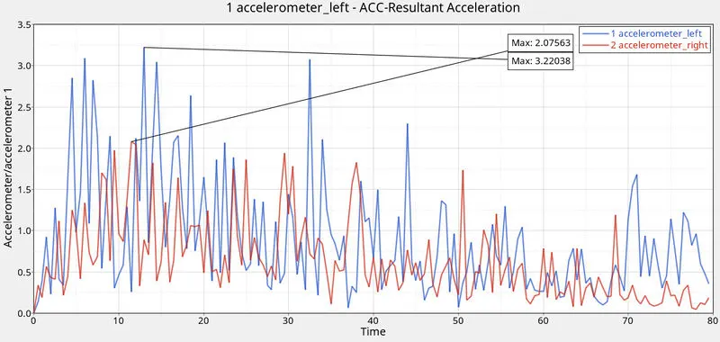
The accelerometers are mounted on the base of B pillar will provide the acceleration value. Maximum value of acceleration is observed on the left side.
Intrusions is used to find displacement at the Dash wall. Max displacement of 844 mm is observed at the node with id 66244 placed on the dash wall. Intrusion value can be found out by
measuring the difference between the resultant displacement value and the initial distance of the nodes.
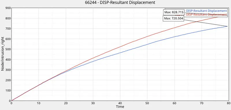
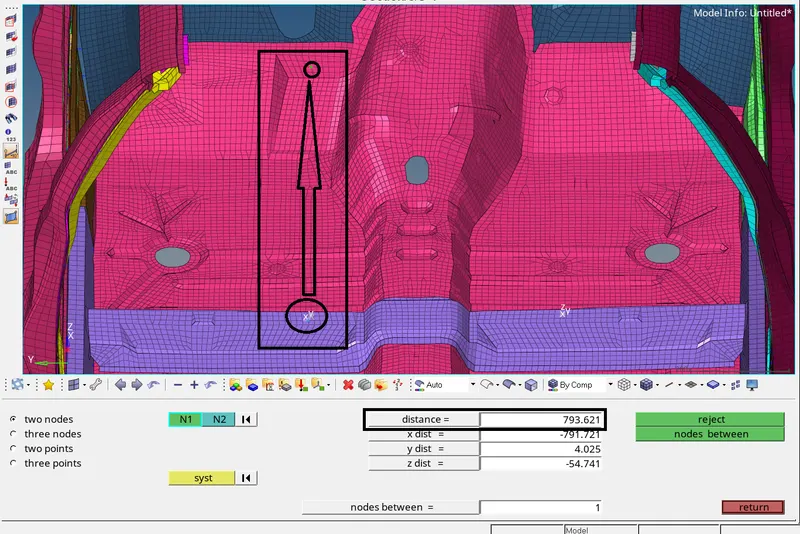
The intrusion at the node with id 66244 is 828.71-793.62 = 35 mm.
- A pillar cross section forces:
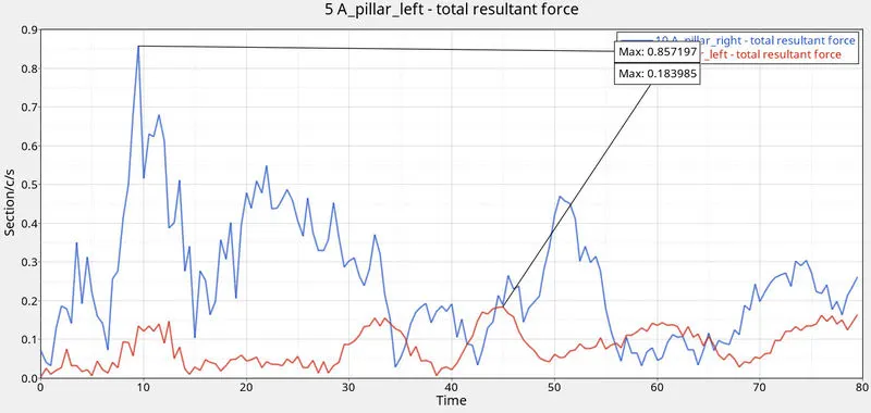
The forces acting on both the A pillar are different. Right side A pillar experineces more forces than the A pillar on opposite site.
- Shot gun cross section forces:
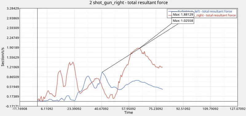
The right side shotgun expriences more forces compared to left side shotgun component.
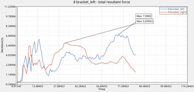
- Bumper plate / Bracket cross section force:
- Rail cross section forces:
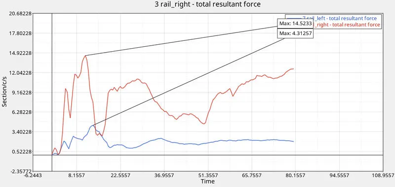
For more accurate results, it is recommended to use a full scale model with all the components instead of reduced model to get better results.
For energy error, negative error means energy is dissipated. The energy error is -1.1% which is close to zero, which is good sign. For the mass error, some mass is added on the nodes during simulation
for time step control. As this error is less than 3 % it is acceptable.
- The energy error and mass error are within acceptable range. The cross sectional forces at some of the important components such as A pillars, bumper plate, shotgun and rails are plotted as they take most of the load after frontal impact. Also accleration curve at B pillar and intrusion at the dash wall is determined. Thus the frontal impact simulation is completed.