Assignment 6-Frontal Crash Simulation Challenge
AIM :
To perform Frontal crash simulation of Dodge Neon BIW structure (reduced model) using Hypercrash/Hypermesh to preprocess and Radioss to solve.
OBJECTIVE :
- To check unit system and follow [Kg mm ms].
- To create appropriate interface,friction 0.2 and recommended parameters.
- To make sure of no penetrations and intersection.
- To correct rigid bodies if any issues.
- To create rigid wall with friction 0.1.
- To compare the model weight with the full scale 300k nodes model and use added masses to reach target weight 700kg while getting CG about the required range.
- To apply Initial velocity 35 mph.
- To ensure good quality of model.
- Setting Time-step :0.5 microseconds.
- Setting Runtime 80 ms.
PROCEDURE :
Crash Test :
A crash-test is a form of destructive testing usually performed in order to ensure safe design standards in crashworthiness and crash compatibility for automobiles or related components. To test the cars safety performance under various conditions and during varied types of crashes, vehicle manufacturers crash test their cars from different angles, different sides and with different objects, including other vehicles.
The most common types of crash tests are listed below :
- FRONT IMPACT TEST
- FRONT OFFSET IMPACT TEST
- SIDE IMPACT TEST
- ROLL OVER TEST
Front Impact Test :
In this test, a full vehicle is set up with all the required equipments and structures and it's made to collide with a rigid wall which depicts the collision with any other vehicle or a barrier or any obstacle ahead.
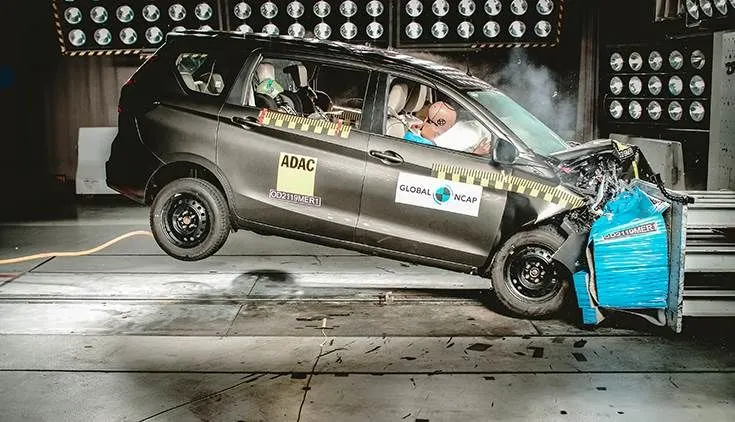
For this project, The case setup and solving is to be done on Hypercrash and Hypermesh using Radioss solver. Hypergraph 2D and Hyperview is used to view the results and for post processing. Hypergraph 2D is used to view the Time History files of the Global variables like the Internal energy, Kinetic energy and Contact energy etc whereas the Hyperview is used to view the animation wherein it displays the overall deformation of the structure and used to view the simulation of displacement, von-mises stress, Plastic strain etc.
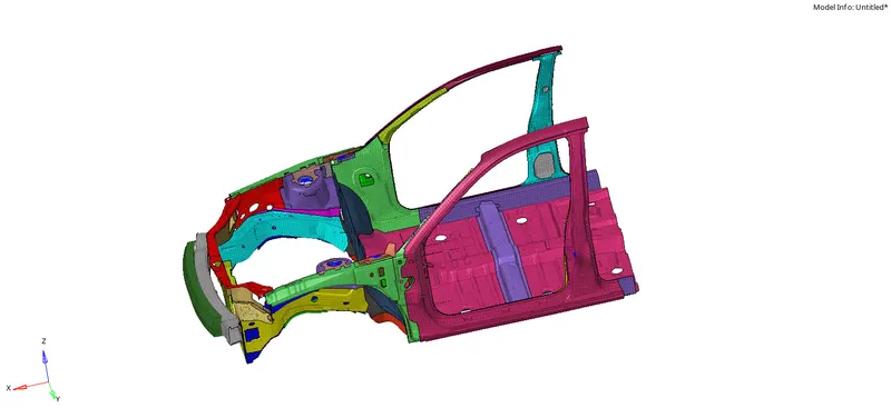
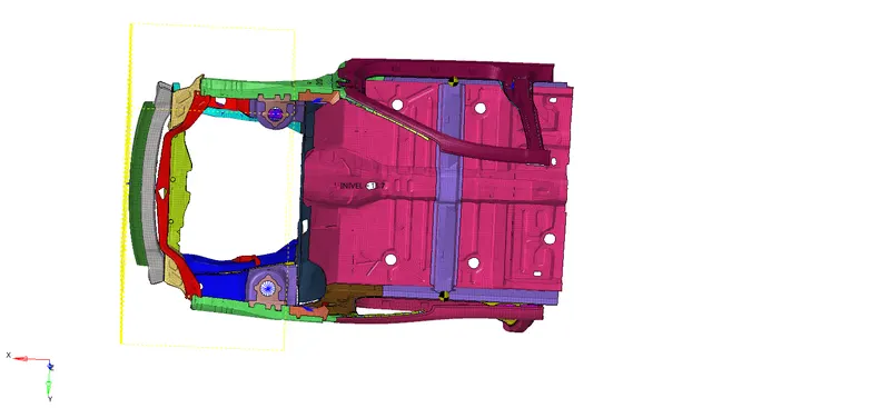
Here, since we are using the student edition software and the number of nodes usage are restricted to 10K, the model complete model has been reduced to BIW structure wherein the portion required for this frontal crash simulation is alone used. Here, the model is free from other components like, Body, Engine, Suspension system, wheels and tyres and Door etc.
The total mass of the reduced BIW structure is found to be 188 Kg and the required total mass should be around 700 Kg. So we can use this mass difference to set the COG of the model at most realistic place. Since this is a BIW model which is reduced for Frontal Impact, the COG location is not considered for the Z-axis location as we don't have the Suspension and wheel components to be considered. Generally the COG of the car would be somewhere in the middle and near to the Driver seat (around the cross component) while neglecting the Z-axis location.
Proceeding to the Case setup :
1. Unit system check :
In order to check the Unit system of the given model, either we can open the given _0000.rad file in the notepad or else we can directly open the given model in the Hypermesh window >> Models >> Cards >> BEGIN CARD.
Check the BEGIN card to see what is the Unit system followed in the given model.
Here is the given parent model :
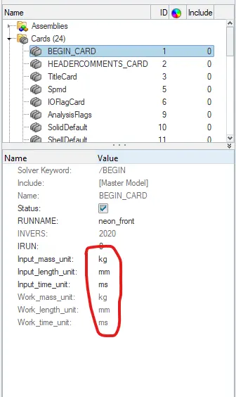
As we can see the given model uses the Kg,mm,ms unit system.
2. Check Penetrations and Intersections :
Now, Open the Hypercrash Interface from the Hypermesh. Go to Hypermesh >> Applications >> Open Hypercrash >> Default unit system as kN,Kg,mm,ms.
Now, Import the given parent model there and go to Quality >> Model checker >> Check all solver contact interfaces.
Or we can do the same check in the Hypermesh window. Go to Tools >> Penetration check >> Type : Intersection and Penetrations >> Select all components and click check.
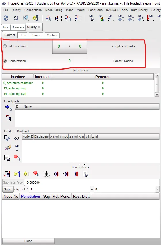
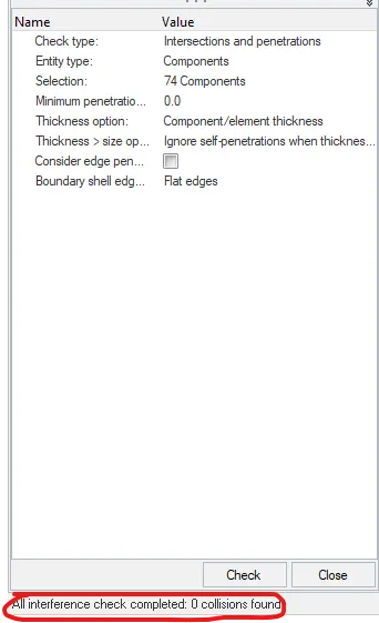
As we can see the model is free from any Intersection and Penetration.
3. Mass Balancing :
As we know that this BIW structure is reduced for frontal crash simulation and hence the total mass is about 188 Kg. However In comparison with the Full scale model, we can add some mass in the BIW structure to reach the 700 Kg target total mass. Also the COG of the body should be kept and placed in the most realistic orientation so as to represent the simulation accurately. The COG determines the vehicles Handling characteristics in terms of Vehicle Dynamics and plays an Important role in Crashworthiness since the orientation of the COG point affects the vehicle's Pitch, Yaw and Roll in which when the vehicle hits an obstacle it's COG determines whether the vehicle is going to flip over or stays grounded. Higher the COG,more the chances of Roll over and lower the COG less the occurence.
To check the total mass of the model, Go to Hypermesh >> Tools >> Mass details >> Check Mass, COG, Inertia details to see all the details.
We can also use Hypercrash to locate the COG and see the mass of the model. Go to Hypercrash >> Mass balancing.
We can see the Mass details. Click on the View button to see the location of the COG of the model.
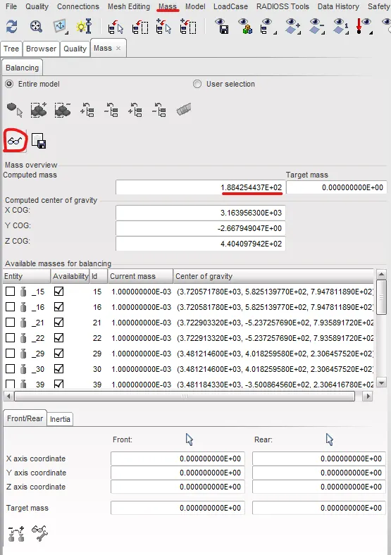
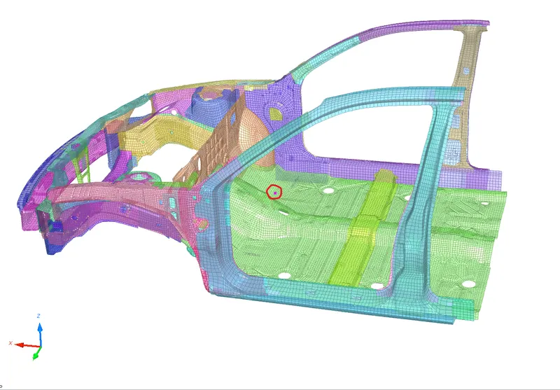
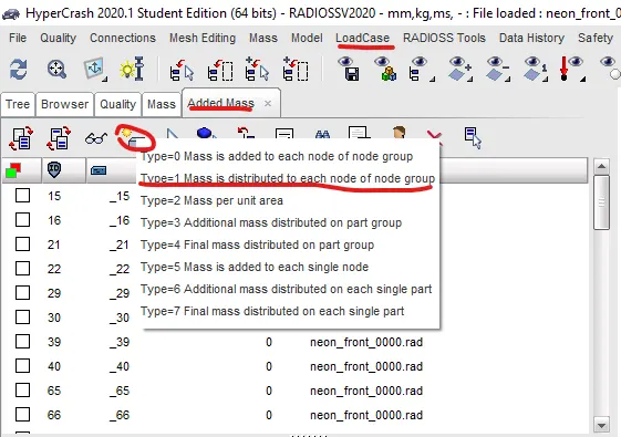
Now, to add mass and moderate the COG point, go to Hypercrash >> Load case >> Added mass >> New >> Select Type:1 >> Select the Group of nodes >> Enter Mass ( required )
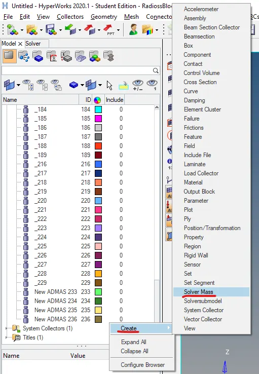
We can also add mass in Hypermesh. Right click in Model Browser >> Create >> Solver Mass >> Select Type 1 >> Select the Nodes and Enter the mass.
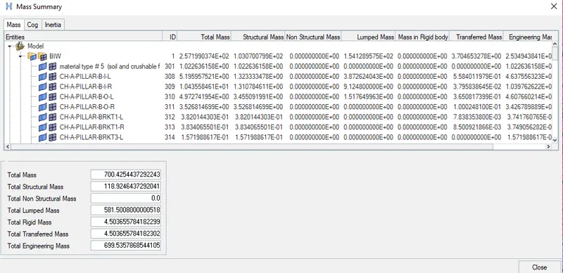
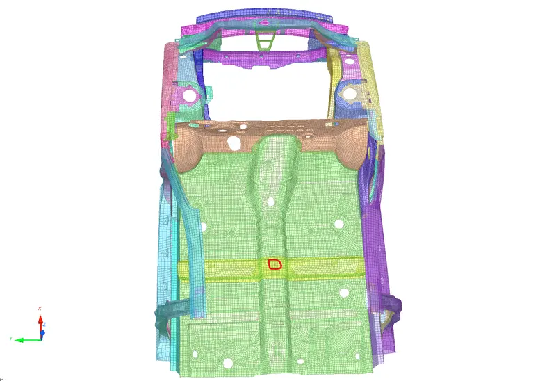
In this model, to reach the Target mass 700Kg, we can add mass in Front and Rear cabin areas. In front driver side and passenger side, we can add the mass of Seats. Then in the mass of rear seat bench is added such that the node selection would make the mass to be distributed properly to get the COG exactly in the middle of the cross component of the BIW structure irrespective of the Z-axis orientation.
Here is the COG of the model and the total mass added :
4. Type 7 Interface :
Now, Export this model from Hypercrash and open the same in the Hypermesh. After Importing, to create the Self Impact Interface, Go to Hypermesh >> Solver >> Inter >> Right click and create.
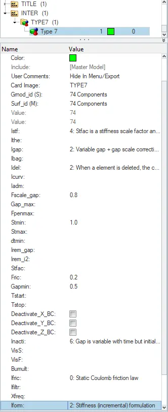
Delete all the present interface and create a new one with Type 7 and Enter all the required Parameters. As we are using self impact interface, we can use all the components as both slave and master. Enter all the other required parameters like Inacti, Igap, Gap_min etc
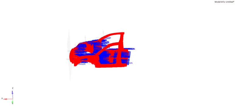
Here is the Type 7 Interface which is defined as Self Impact.
5. Rigid Wall Creation :
For the creation of rigidwall, Go to Hypermesh >> Solver >> Right click >> Create >> Rigid wall >> Plane.
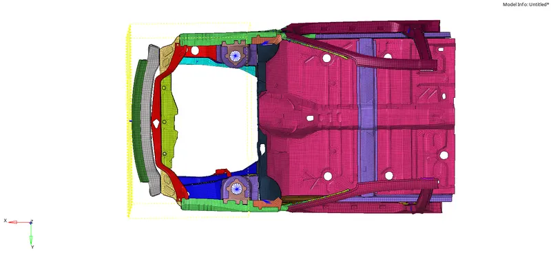
Now, we need a reference node to create the Rwall, so create a temporary node which is in the front most structure of the model (Bumper). Now, translate that created node to a particular distance say 20mm such that the rigid wall should not touch the model. Now, note the orientation points of that node along all the axis. Enter the same orientation points in the Rwall section at XM,YM,ZM column. The normal should be acting towards the negative axis and so the normal is given as (-1,0,0). Add Sliding friction mode and provide the Friction as 0.1 which is recommended. Enter Dsearch distance as 1000. Enter Grnode set as all the nodes so as to represent the whole component as the slave node to the rigid wall. Hence the Rigid wall would be created.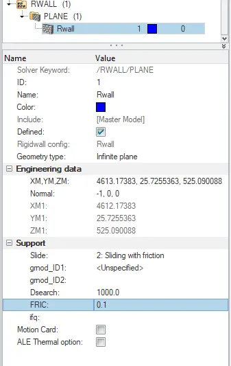
6. Create Initial Velocity :
Now, to create Initial velocity, Go to Hypermesh >> Solver >> Right click >> Create >> Boundary Condition >> Inivel.
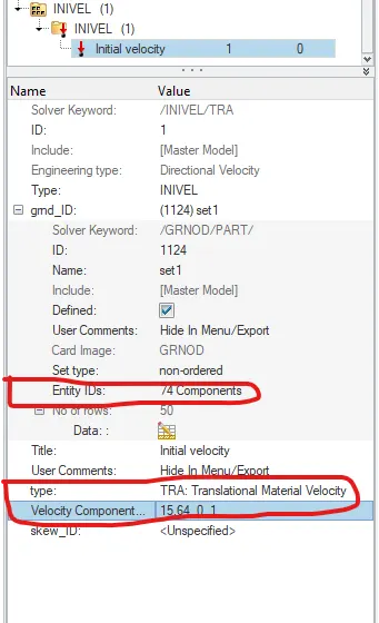
The required Initial velocity is 35mph. The current unit system in the model is Kg,mm,ms so to convert mph to mm/ms, 1mph = 0.447mm/ms. So 35mph = 15.6464 mm/ms.
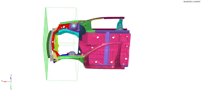
The Initial velocity is to be applied to the whole component and all the nodes present in it. The applied velocity should be in the direction towards the rigidwall.
So, the axis should be given as (15.6464,0 0) such that the applied velocity would move towards the rigid wall.
7. Create Sections :
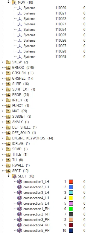
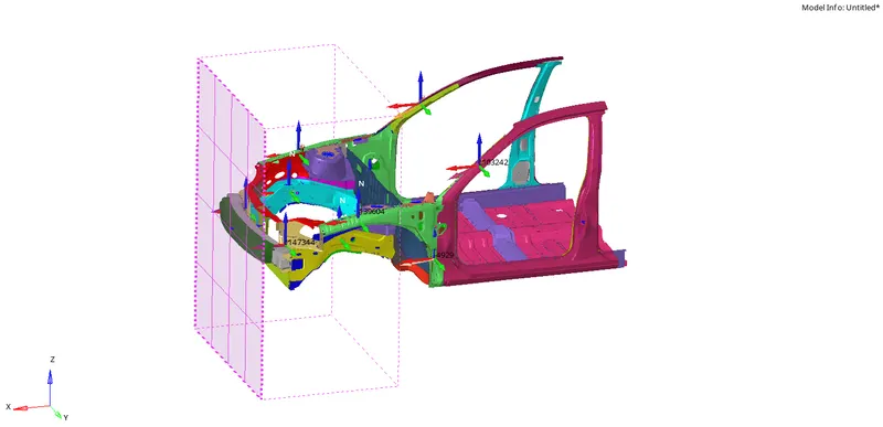
Now, we need to create several sections so as to observe the forces crossing across those cross sections. The cross sections were required in A-Pillar, Shotgun, Hinge Bracket, Rails, Headlight Bracket on both sides which means we need to create around 10 cross sections across both sides LH and RH.
To create these cross sections we need to create frames wherein they're a type of reference co-ordinate system where the quantities defined follow its own origin. The Moving Frames are those in which the Frame moves along with the defined nodes from the origin.
These are created in such a way that the normal (z-axis) are facing the rigid wall. These are created to study those local quantities along the cross section in a direction where the model is forced towards the rigid wall.
Now, Firstly the location of the nodes are found by using Find command in the Hypermesh. Go to Hypermesh >> Tools >> Find >> Nodes >> Node ID >> Number >> Enter.
This will give the visual representation of the particular node in the model with its number. A temporary node is created in that Node ID along the required place.
Then, go to Hypermesh >> Browser window >> Solver >> Right click & create >> Frame >> MOV
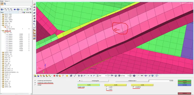
Here, we need to select Node by reference Option to represent the local coordinates. Select YZ plane, Select Origin node as the node of Interest >> Select Z axis (towards rigid wall) and select another node to define the Y-axis. Thus it will create the local coordinate system.
Similarly we should define the moving frames for all the required cross section along the model.
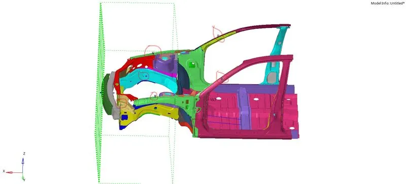
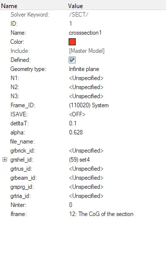
Once the moving frames are created, then we can create the cross sections. To create the cross sections, go to Solver browser >> Right click & create >> Section >> Sect
Now, Instead of using N1,N2,N3 Since we've already created frame of reference, Select the Frame by directly clicking on it.
Then Give DeltaT as 0.1 and Alpha value as 0.628 (default). Also we need to create the cross section elements wherein we're interested to study the behaviour of elements upon crashing. Grshell ID >> Right click & Create >> Elements >> Select the elements across the cross section.
Then Enter the Iframe as 12 (COG of section). Thus the cross section with the defined Frame is created. The same process has to be carried out at all the cross sections to be defined.
8. Create Accelerometer :
Accelerometer has to be defined along the B-Pillar Rocker. This accelerometer is required to measure the acceleration forces on the body exerted by the gravity or motion.
In order to create the accelerometer, Go to model browser >> Right click & create >> Accelerometer >> Select the node ( node of interest ) and click create.
Here we need to define two accelerometer, Each on two B-pillar rockers.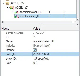
9. Intrusions on dashwall nodes 66695, 66244 :
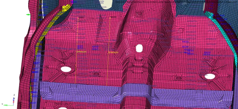
Intrusion study on the dashwall nodes has to be done. It can done by either defining a local coordinate (frame) along a part exactly opposite to the Dashwall nodes of interest and its displacement according to the defined frame can be studied or else we can create a Spring 2 node element along those two nodes and opposite nodes and study the total deflection on the spring.
Here we are defining Spring2 node element across those two nodes. Go to Hypermesh >> 1D >> Spring >> Spring 2 Nodes >> select nodes and create.
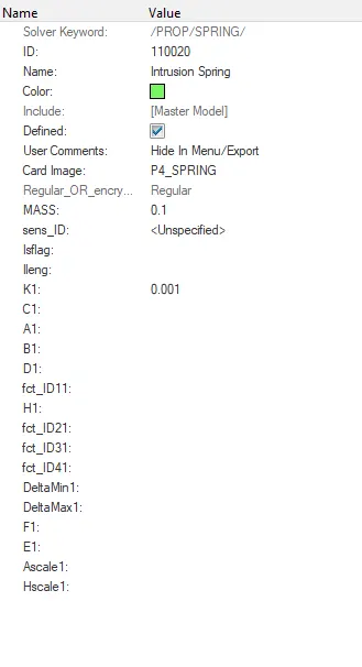
Now, we've to create the Spring property for those two nodes. In spring property select P4_spring card and enter mass as 0.1 and K (stiffness) as 0.001.
Since our aim is to capture the intrusion on nodes, such low mass and sitffness would not affect the forces on the nodes which provides at most accuracy in capturing the node displacement.
10. Setting Output requests :
We need to request the outputs of our interest. In default the solver would give the outputs of Time history of Global variables, Rwall forces and the Animation files of displacement, von misse etc. Other than that, we need to seperately request all the other results. Here for this model, We need the Time History of :
All cross section forces ( A-Pillar, Shotgun, Rails, Headlight Bracket, Hinge)
Intrusions on Dashwall Nodes ( Spring Intrusion )
Rigid wall forces ( Rwall )
Accelerometer results ( on B-Pillar rocker )
Go to Hypermesh >> Solver >> Right click & create >> TH >> Required Outputs.
Select the Entity ID accordingly and create requests for each part seperately. Hence we can get all the required Output requests.
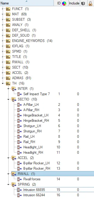
These are the Outputs which are requested.
11. Other settings :
The Other final settings would be setting up the Minimum time step, Total run time etc. The total run time is set to 80ms. The Minimum Time step is kept at 0.0005.Here are the other time step and scale factor settings.
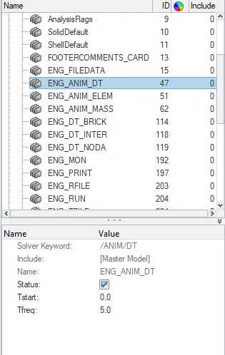
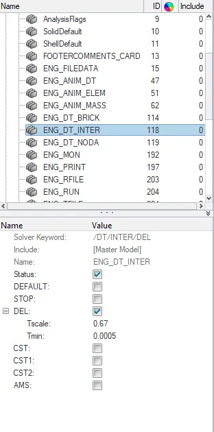
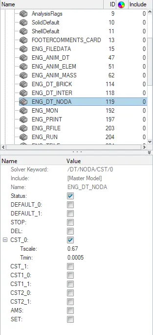
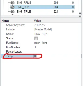
With all these settings, Now we can check the model for any possible errors like any Incompatible Kinematic condition, Unsupported cards, Unused parts and properties etc.
Export this Model as Solver Deck and Open the same in the Hypercrash to run the model checker as the Model checker in Hypercrash is quite accurate than the one in the Hypermesh.
Or else we can also change the Engine run time to (Tstop 0.001) and run the simulation to see what're the errors and warnings and If it is free from any errors, then again we can set the Run time to 80ms and can run the whole simulation.
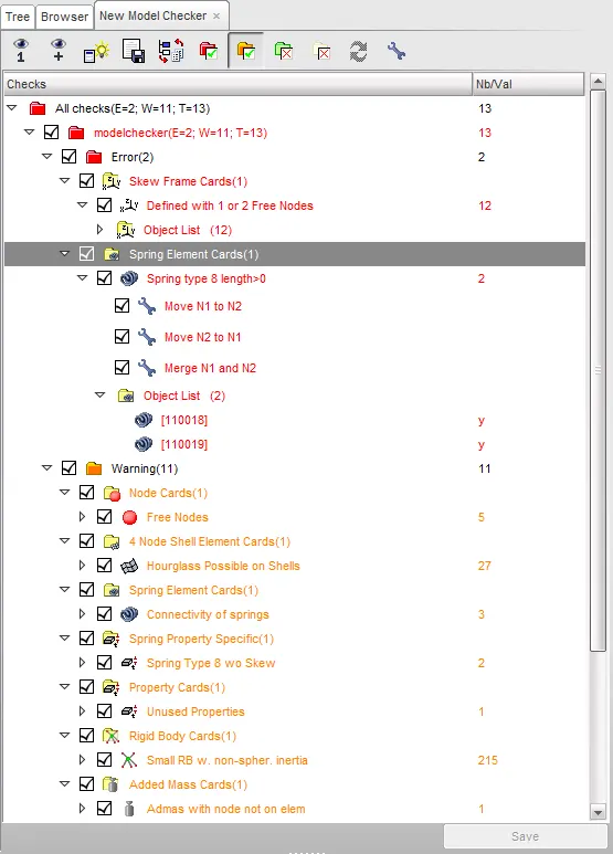
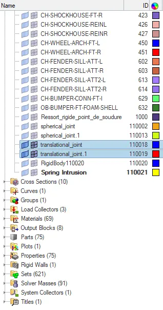
As we can see there are two errors Indicated and some warnings. Those warnings can be fixed in Autofix option. The errors indicated were unwanted and unused Translational Joints in the model, We can delete those two translational joints, It's corresponding property,parts and results as we don't need it. Once it is done, the model would be free from any errors.
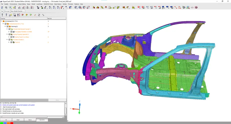
Again we run the model checker to make sure whether all the errors have been cleared.
Note : We can't always rely on the model checker to see the errors and warnings, Sometimes the solver do show some error even after fixing it. So, we can run the simulation for a very less time say 0.1ms and see whether the simulation runs without any error and then we can proceed to full model run.
Now, since all the errors are clear and all the case were setup, We can run the simulation.
Go to Hypermesh >> Analysis >> Radioss >> Options : -nt 4 >> Include connectors

Outputs :
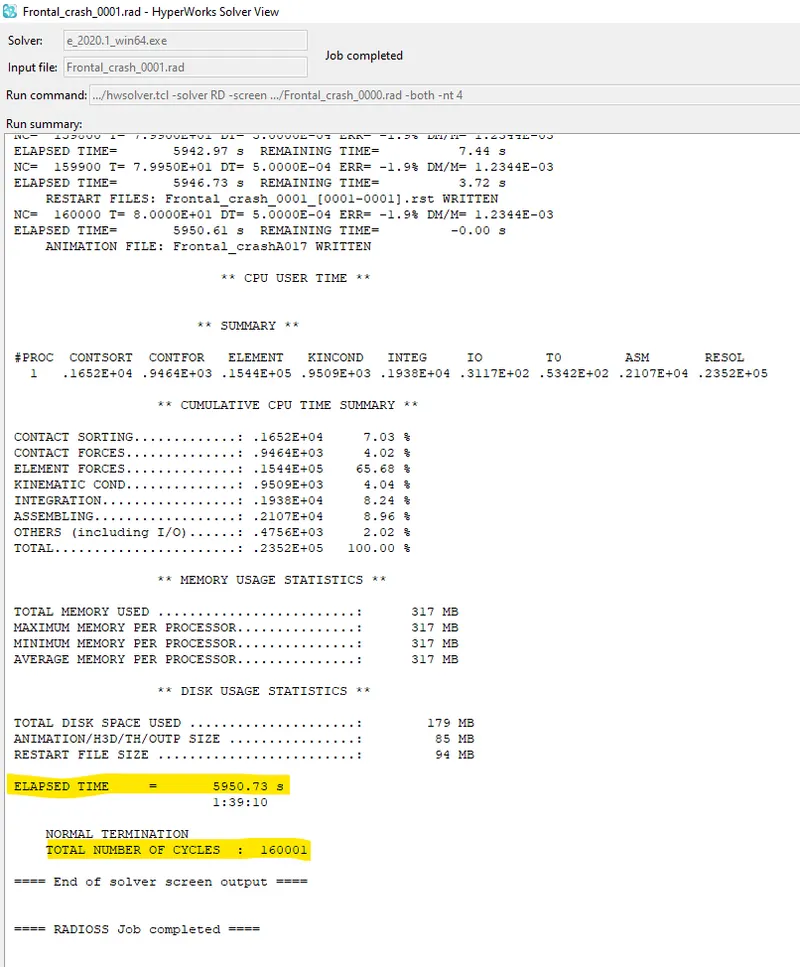
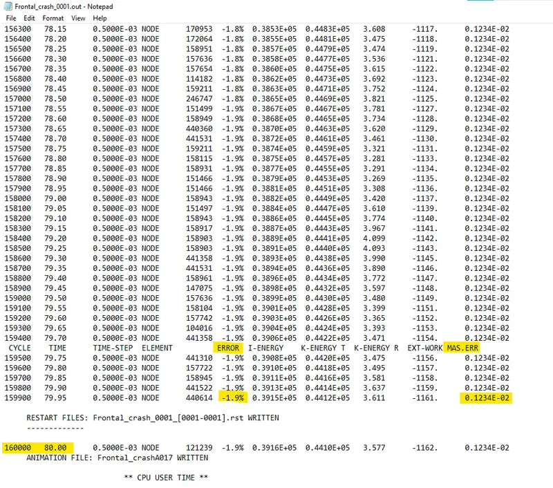
We can see that the Total time taken for running is about 5950.73s and the total number of cycles is 160001. The Energy error is reached a maximum of -1.9% and the Mass error is about 0.1234E-02.
These Energy error and Mass error values are well within the nominal range and so we can proceed with the review of the Time History files and the Simulation.
Animation output :
Open the .h3d File in the Hyperview to see the Animation of the crash and to see the displacement, Von-mises stress and Plastic Strain produced in the Model.
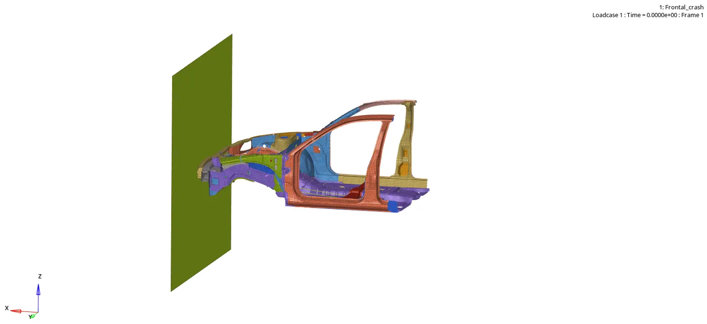
As we can see that the vehicle after crash is moving upwards. This is due to the fact that the Centre Of Gravity is not defined properly in Z axis. Also the model has been reduced to BIW structure which is free from Engine blocks, Exhaust and Intake manifold, Suspension and wheels etc.
Displacement :
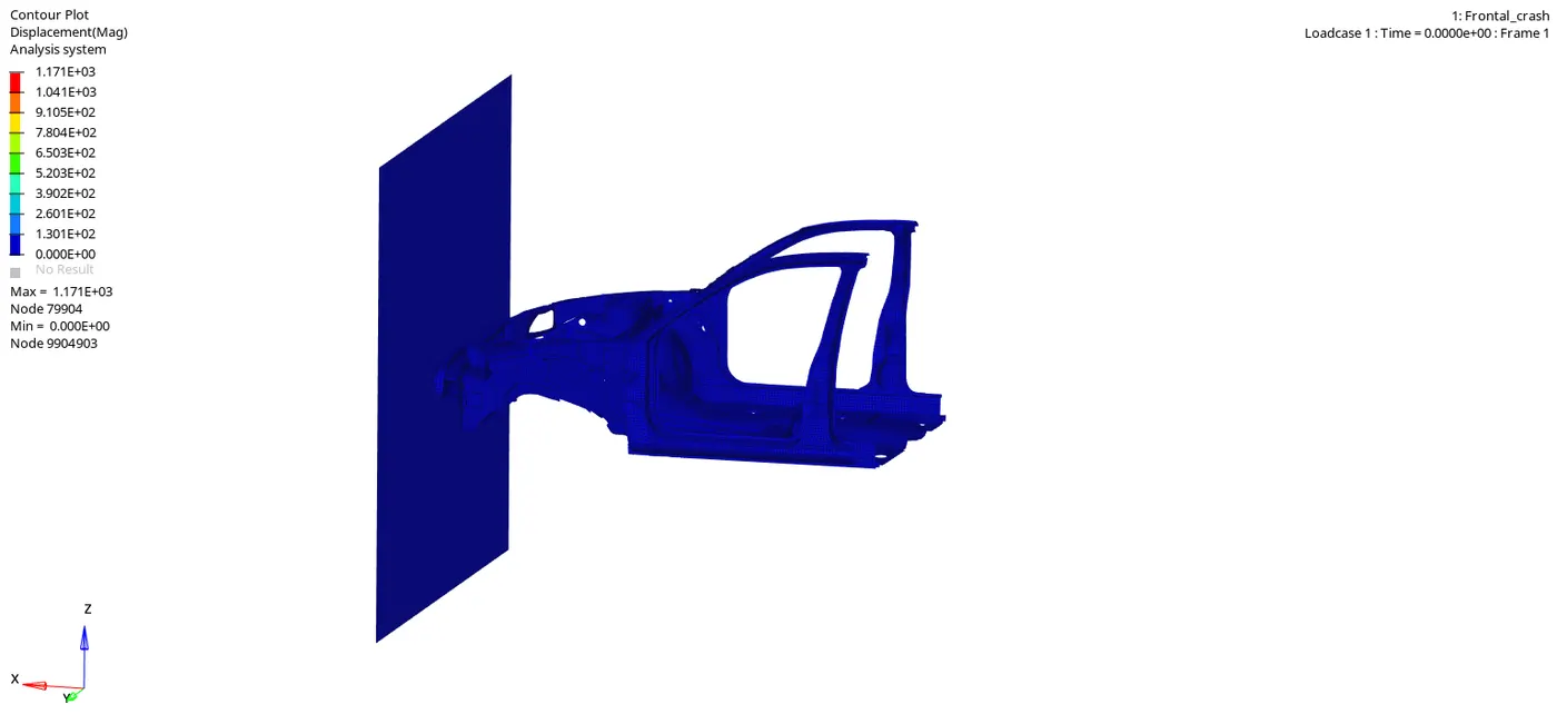
As we can see from the above animation, the maximum displacement was found to be 1.171E+03 mm. The bumper initially starts crushing and then the forces from the bumper are getting transmitted from the Bumper to the A-Pillar and B-Pillar through the Rails and the Fender and reaches the farther parts. The forces were getting reduced from the initial to final stages due to energy absorbtion.
Vonmises Stress :
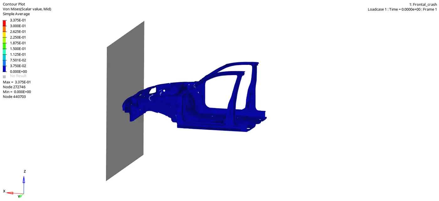
The stress is distributed across the BIW structure from the Bumper to the rear end and we can see there are very minimal parts wherein we can observe stress concentration. The Maximum stress produced is about 0.3375 kN/mm^2
Plastic Strain :
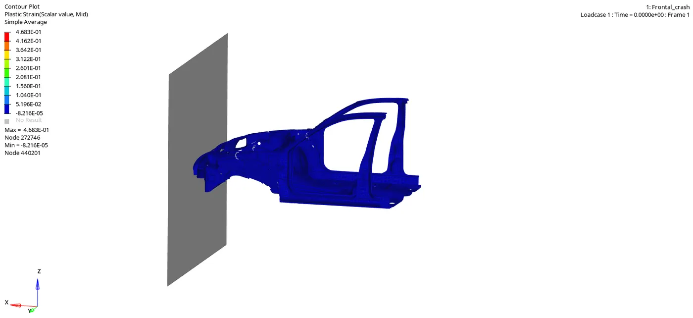
As we can see that the plastic strain is about 0.4683.
Time History Files :
Now, Let's see the outputs which we've requested in the solver. Go to Hypergraph 2D >> Import the .T01 file in it.
RWALL FORCES :
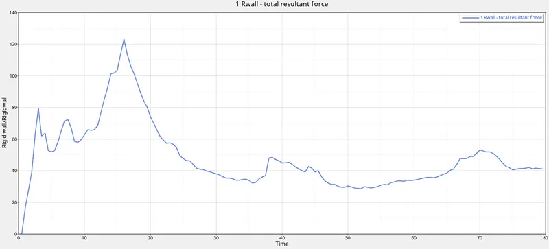
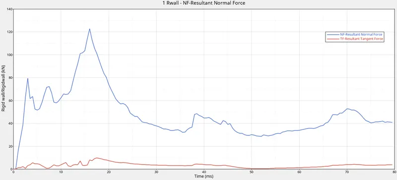
The Rwall forces as we can see start from 0 and it reaches a maximum after 10ms and then gradually decreases and almost maintains a certain value around the ballpark 40kN. This is because the Wall experiences maximum force once the bumper crushes on it and as the vehicle involves in energy absorbtion then it gradually decreases.
The Maximum Rwall Resultant Force is around 125kN.
Global Variables :
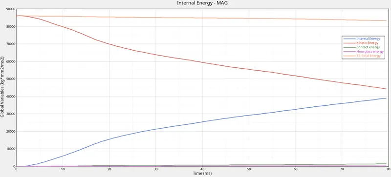
The Total energy of the model remains constant around 85000 J throughout the simulation as it should be. The Kinetic energy is higher at the beginning and it gradually decreases as the deformation starts however the Internal energy is vice versa to Kinetic energy. It is minimum at the beginning and gradually increases.
The Hourglass energy is almost non existent as we use QEPH elements which has Hourglass control. There is some amount of contact energy since we have provided Friction for the Type 7 Self Impact.
Cross section forces :
1. Rails (LH & RH)
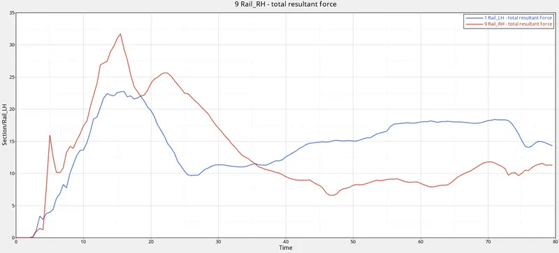
From the graph, we can see that the forces in the Rail in RH Reaches a maximum of 32 kN and the Rail in the LH side reaches around 23 kN.
2. A-Pillar (LH & RH)
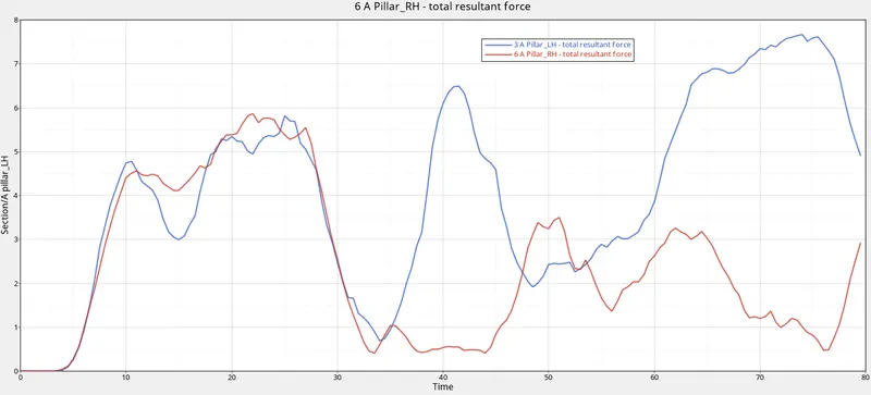
The forces on LH side A-Pillar has a maximum of 7.7 kN and the A-Pillar on the RH side reaches the Maximum of 5.8 kN
3. Shotgun (LH & RH)
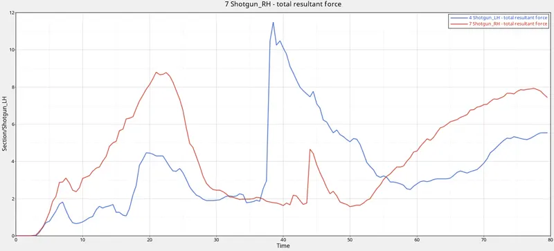
Similar to the A-Pillar, the forces propagating on the Shotgun LH reaches the maximum of around 11.5 kN and the RH side Shotgun reaches around 9 kN.
At Initial stages on both sides the forces experienced were low and when the deformation progresses, the forces were increasing and it is found to be maximum on the LH than the RH side.
4. Headlight Bracket (LH & RH)
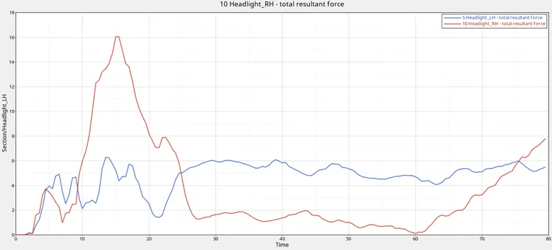
We can clearly see that the forces were maximum in the RH side bracket than the LH side, Since In the RH side we can observe some stress concentration in the simulation.
5. Hinge Bracket (LH & RH)
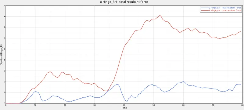
The forces were seen maximum in the RH side about 8 kN and on the LH side it stays minimum around 2 kN. These were all the cross sectional forces which are of our output requests.
Accelerometers (LH & RH) :
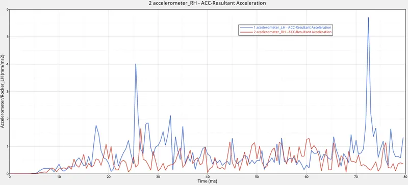
The acceleration on the LH side Rocker reached the maximum of around 5.5 mm/ms^2 and on the RH side is around 1.5 mm/ms^2.
Intrusions on Dashwall Nodes ( 66695,66244) :
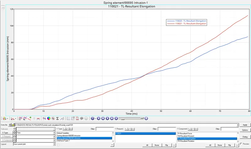
The total deflection on the Node 66695 is about 87mm and the node 66244 experienced 110mm deflection. These values were comparitively lesser and so we can say that the Driver and the passenger legs in the Front seats wouldn't be injured severly. The same can be visually seen in the animation as there are very less deformation in those regions.
Thus, all our Output requested has been studied and the Crash simulation is done.
RESULTS :
1. We can see that the deformation and the forces were not uniform on both sides (LH & RH). These are due to the facts that the BIW structure used might not be exactly symmetric. The cross section forces were extremely uneven on both sides. This means that the Cross sections created might not be exactly symmetric in both sides. Also the same applies to the creation of Rigid wall. The node used might not be the exact center of the Bumper which resulted in these deflections in the values.
2. The Accelerometer values were higher in the LH side as we see, This is because of the above mentioned reason and so the vibration and spikes of acceleration and deceleration were not even on both the sides Rocker.
3. The Intrusion of the Dashwall nodes were referring to the deformation of the nodes around the foot pedal region. The values were very lesser and so it depicts that the driver and the passenger won't be injured severely in those regions.
INFERENCE:
We Finally understood that the Front Crumple Zone ( Engine bay and other components ) Encounters the most forces in crash and abosorbs most of the energy and it is propagated through Rails and travels across the A-Pillar and reaches the rear end. So the design of Front Crumple zone plays a major role in Passenger safety Incase of Front Crash Analysis.