FRONTAL CRASH ANALYSIS OF AN AUTOMOBILE BIW ASSEMBLY
FRONTAL CRASH ANALYSIS OF AN AUTOMOBILE BIW ASSEMBLY
AIM:
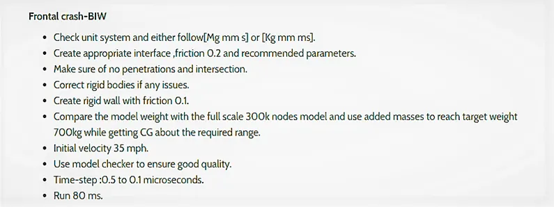
The objective of this project is to study and analyze the behavior of the BIW assembly of an automobile during frontal crash scenario as mentioned below.
INTRODUCTION:
The term crashworthiness expresses the ability of the vehicle structure to protect its occupants in a serious real world crash. The vehicle must be designed such that, at higher speeds its occupants do not experience a net deceleration. A crash-test is a form of destructive testing usually performed in order to ensure safe design standards in crashworthiness and crash compatibility for automobiles or related components. The vehicle manufacturers crash test their cars from different angles, different sides and with different objects. The most common types of crash are.
- Front impact test
- Front offset crash test
- Side impact test
- Roll over test
PROCEDURE:
1. Import the given model to the Hypermesh Radioss profile so has to run the model in Kg,mm,ms unit system.
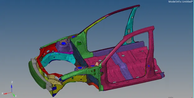
Fig: Imported Model.
2. Check the interfaces and create a new self-contact interface of Type 7 with recommended properties and with friction of 0.2. Delete the other contact interfaces.
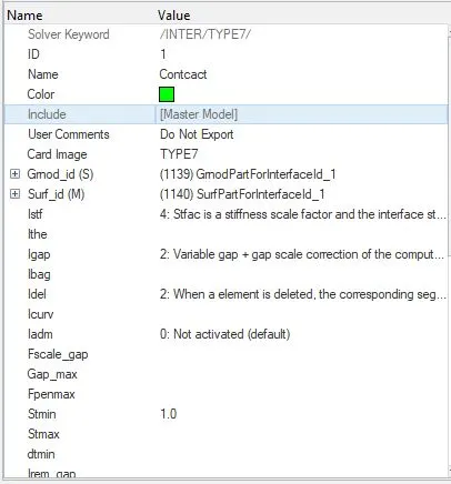
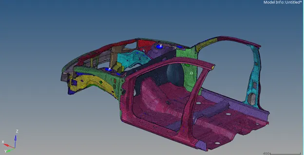
Fig: Interface (Type-7)
3. Check for penetration and intersection for component and group level and make sure there is no collision in the model.
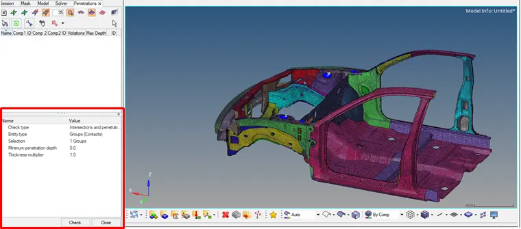
Fig: Penetration and Intersection check.
4. Check the rigid bodies and connections using find connectivity option and make sure there aren’t any flying parts (Free parts) in the model.
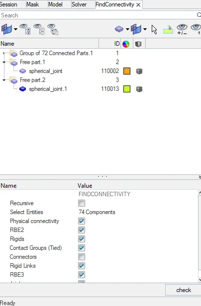
Fig: Connectivity check.
The free spherical joints can be neglected since it will not impediment for the analysis.
5.Open the solver browser and create a rigid wall of friction 0.1 at a distance of 10mm from the bumper of the model as shown in figure. Set the search distance to 1000mm.
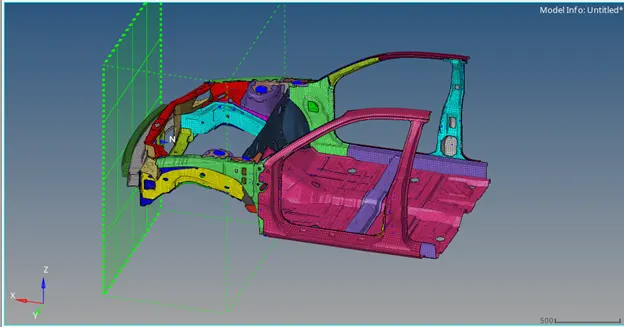
Fig: Rigid wall.
6. Apply the Initial velocity of 15.6464ms (35mph) to all the nodes.
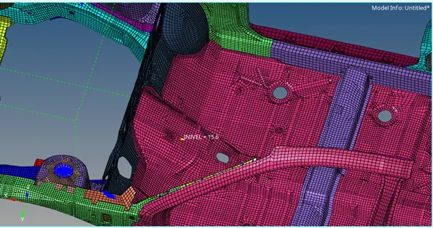
Fig: Initial velocity.
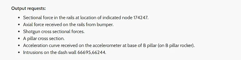
7. Create the frames (moving type) at the mentioned node locations I;e Node 174247, and simultaneously on the other RH rail, Shotgun, A pillar so has to create the sections. The created frame plane must be parallel to the direction of the rigid wall.
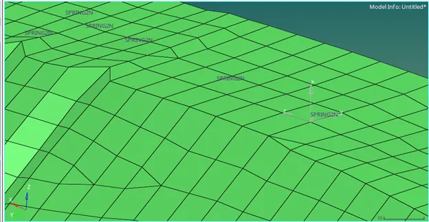
Fig: Created frame.
8. Create the sections using the created frames as shown in order to obtain the sectional forces at the prescribed locations. Make sure that the section plane is parallel to the rigid wall or direction of force propagation. While creating the section enter the DeltaT as 0.1, alpha as 0.67 and set Iframe to 12.
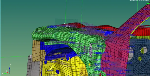
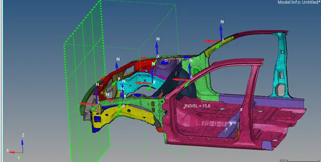
Fig: Created sections.
9. Create a Accelerometer at the base of B pillar as shown in figure and set Fcut to 1.65.
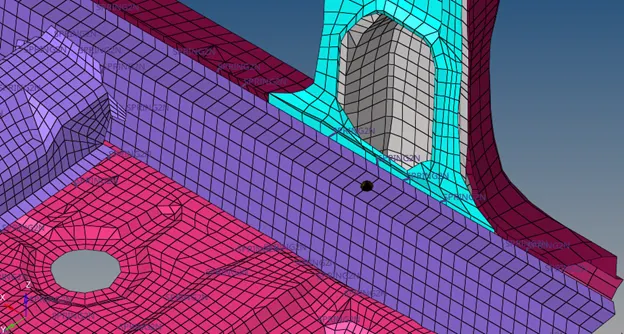
Fig: Accelerometer.
10. Open the engine keyword set the Run time to 80ms in the run card.
11. Crate animation cards like ANIM/MASS, ANIM/VECT, ANIM/ELEM, ANIM/NODA, set ANIM/DT Tfreq to 2.67 (30 frames).
12. Set the time step of 0.0005ms (0.5microsec) in the DT card and set all DT/SHELL, DT/BRICK, DT/INTER, DT/NODA with constant time step (CST). For Brick and Shell set Tscale value to 0.9 and for rest of the cards set to 0.67. Select the required parameters from the card.
13. The output requests will be created using TH card, create a TH card for the Sections, Rwall, Part, Accelerometer select the created credentials and request for the Default variables.
14. The TH nodes will be created in order to measure the Intrusion on the dash wall. So the nodes 66695, 66244 and another node from the other side is selected and separated TH cards are created, select the nodes and frames in the card. Since the output required is only with the Displacement so select the variable as displacement in x,y,z.
15. Check the Mass and COG of the model using Tools- Mass details – Mass, cog and Inertia. The COG of the model must lie approximately behind the Seat location (At Seat Reinforcement beam)
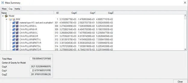
Fig: Mass summary.
16. In order to obtain the CG at the required location the additional mass has be added to the model limiting the total weight of the model to 700kg.
17. To add the mass create ADMAS select the mass type as 1 (Mass/N), Enter the mass value and select the nodes. Usually in general case the mass of passenger will be added to the location of the seat as shown. Balance the magnitude to obtain the CG in X axis.
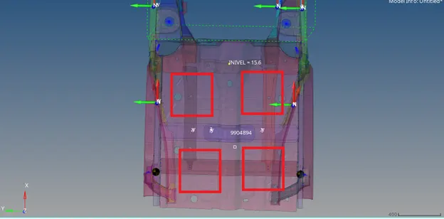
Fig: Mass applied.
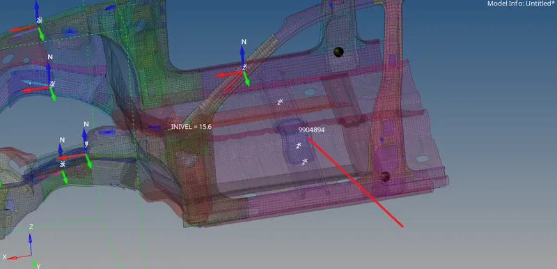
Fig: COG point.
18. Finally run the model checker to check the error and potential warnings. Tools- Model checker – Radioss Block – Run.
19. An error of material property appeared which can be omitted. Run the simulation in radios with 4 core threads and Plot the results required.
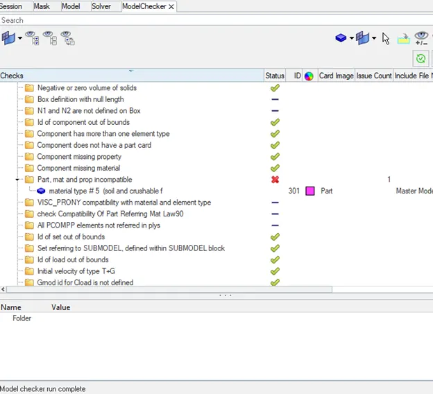
Fig: Model checker.
RESULTS AND DISCUSSIIONS:
Energy error and Mass error:
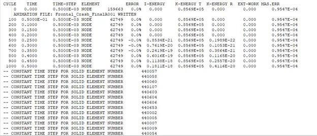
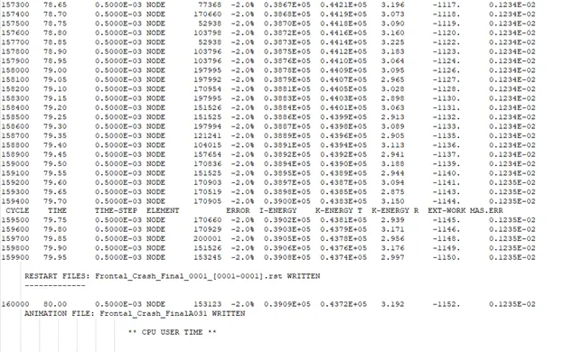
The energy error and mass errors were found to be negligible since the magnitude of errors is in the accepted level. The min Energy error is 0% and maximum of -2%, The min mass error is 0.9547E-04 and maximum is 0.1235E-02 (less than 2%).
Displacement:
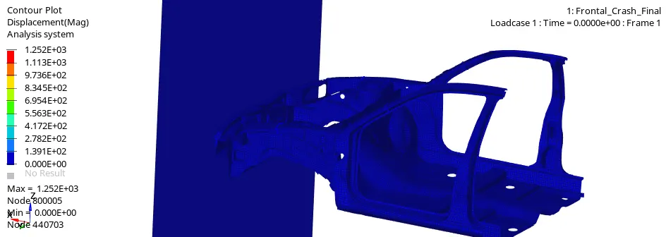
The maximum total displacement of the model was found to be 1252mm.
Stress and Strain:
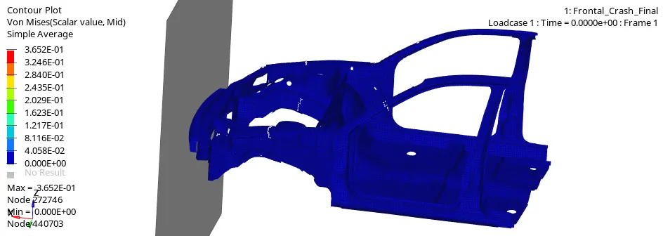
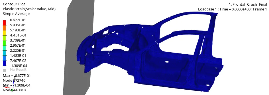
The maximum Von mises stress on the model is found to be 0.3652 and Plastic strain was found to be 0.6677.
Contact force:
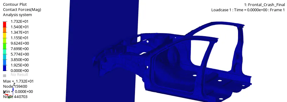
The maximum contact force was recorded from the analysis was 17.32KN.
Sectional Forces:
Rails
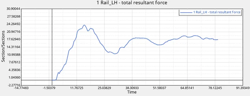
The maximum force at node 174247 of rail was found to be 24.24KN.
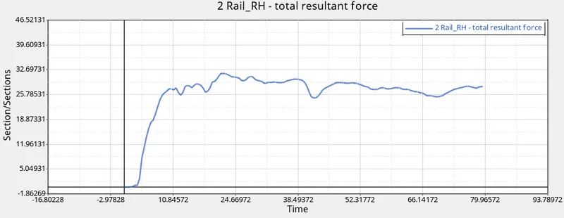
The maximum force at the section of RH rail was found to be 32.5KN.
Force transferred to the rail from Bumper
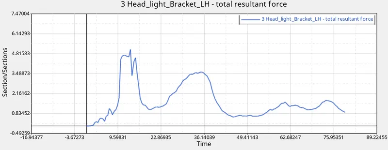
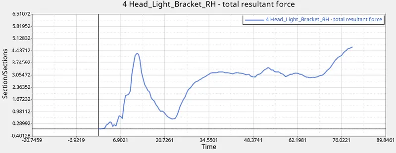
The maximum force transferred to the rail from bumper is found to be 5.2KN in LH rail and 4.3KN in RH rail.
Shotgun
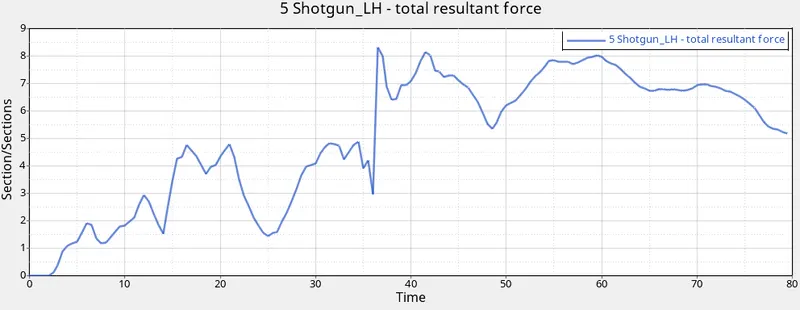
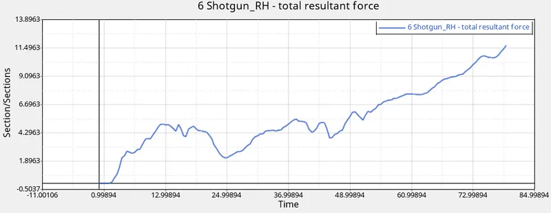
The maximum sectional force recorded on shotgun was 8.4KN in LH rain and 11.51KN in RH rail.
A Pillar
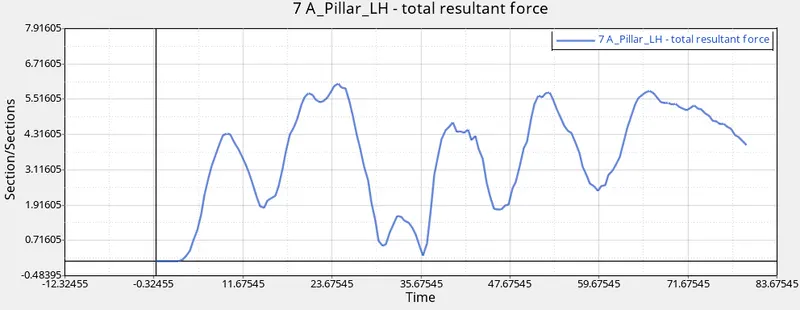
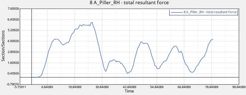
The maximum sectional force recorded on the A pillar is found to be 6.1KN in LH and 6.2KN in RH.
Acceleration
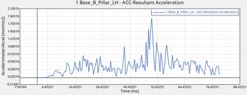
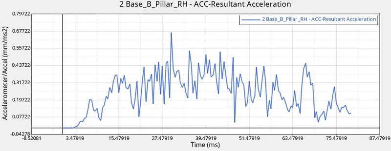
The maximum acceleration recorded at the base of B pillar is found to be 1.86 mm/ms^2 in LH and 0.66 mm/ms^2 in RH.
Intrusions on the Dash wall
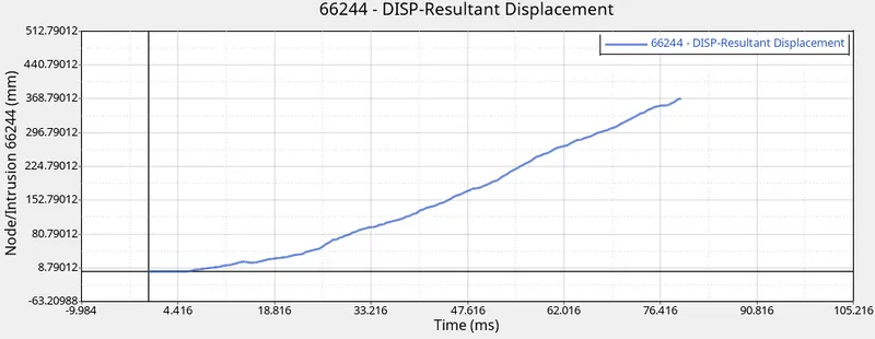
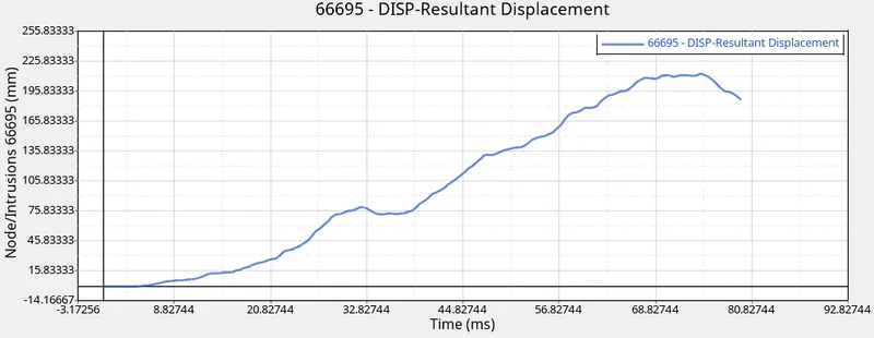
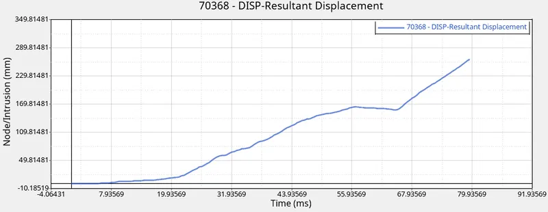
The total resultant displacement (Intrusion ) was found to be 368.79mm at node 66244 and 210mm at node 66695. A displacement of 260mm was recorded in the dash wall at RH side of the model.
Rigid Wall Forces
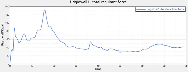
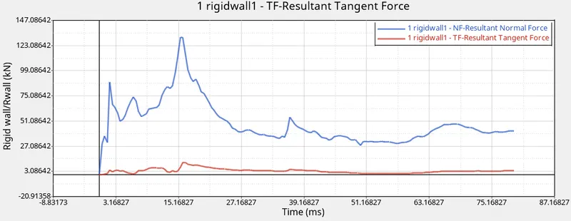
The maximum total resultant force of the rigid wall was found to be 131KN.
Global variables
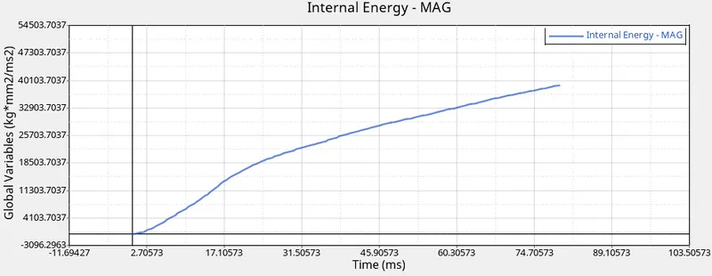
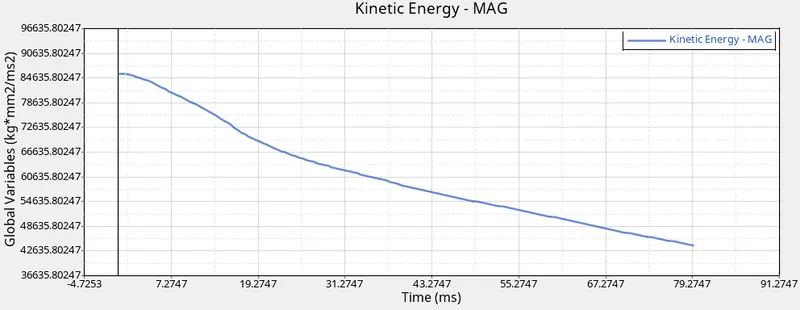
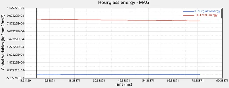
The maximum internal energy of the model 40000 kg mm2/ms2 and kinetic energy decreases as the load increases. The hourglass energy was negligible and constant and the total energy remained constant throughout the simulation.
CONCLUSION:
By comparing the output results the frontal sections of the car model will absorb most of the energy and the rail section receives much forces. The intrusion on the dash wall is significantly high due to the absence of cross car beam and reinforcement bars and other engine components. The energy error and mass error were acceptable and Hourglass energy was negligible. Most of the forces were distrubuted to the front end components and a small portion of the force will be transferred to the A pillar.