Assignment 6-Frontal Crash Simulation Challenge
Aim:- setup perameter for forntal crash analysis as given in challenge.
Question:
Frontal crash-BIW
- Check unit system and either follow[Mg mm s] or [Kg mm ms].
- Create appropriate interface ,friction 0.2 and recommended parameters.
- Make sure of no penetrations and intersection.
- Correct rigid bodies if any issues.
- Create rigid wall with friction 0.1.
- Compare the model weight with the full scale 300k nodes model and use added masses to reach target weight 700kg while getting CG about the required range.
- Initial velocity 35 mph.
- Use model checker to ensure good quality.
- Time-step :0.5 to 0.1 microseconds.
- Run 80 ms.
Case setup:-
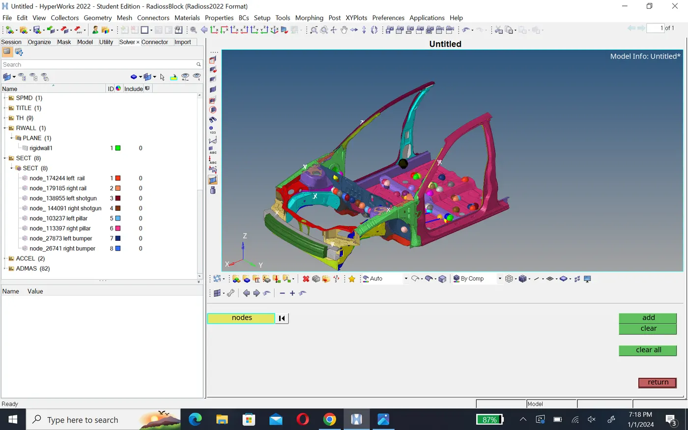
- First we import the model file .rad starter file in radioss (neon_front_0000.rad) using import solver deck option. then we will check the unit system of the model which found under the Begin_card. So for this model we will see that the unit system in (kg mm ms). Now we will create all the required things for a frontal crash.
Penetration check:-
To check penetration, we will go to Tool menu menu bar and click on penetration check option.in penetration check panel,we will select all the components and click on check command. The software will check for penetration and then display the result as shown below.
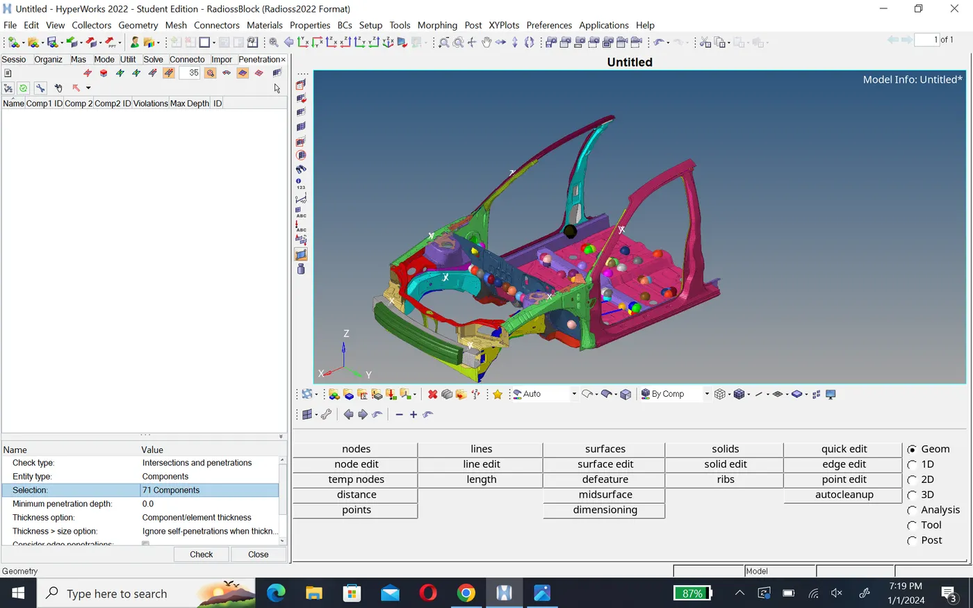
so there are no penetration a or intersections in the model.
Interface:-
For this model, we will create Type7 interface for all the component of the model as it is self-impacting or the nodes anfd elements of the model will have a contact between them.we will go to solver browser and we will delete all the existing interfaces.Then we will right click and create INTER>TYPE7 interface card.we will select all the components for slave nodes and master surface Grnod_id(s) and surf_id(M) respectively.Then we will define all the recommended parameters for type7 interface i.e istf=4,igap=2,fscale_gap=0.8,stmin=1kn,fric=0.2,gapmin=0.5,ifrom=2
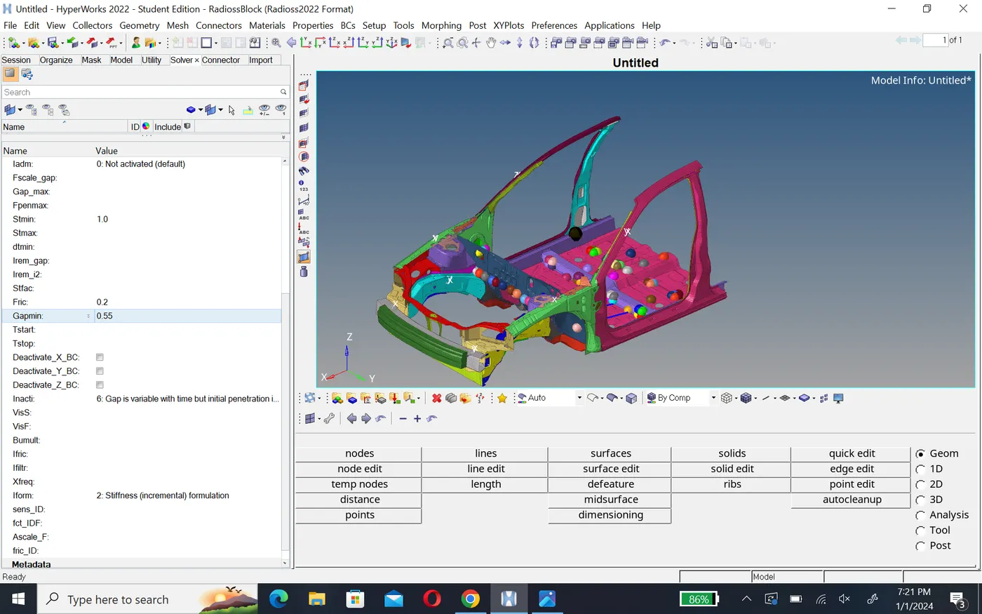
here we will define inacti as 0 which is default there no penetration in the model.
Rigid wall:-
To create a rigid wall at the wall at the front side of the car, we will need a node at the bumper of the car.so we will create node on the element edge using temp node option.Then we will right click on the solver browser and create rigid>plane.
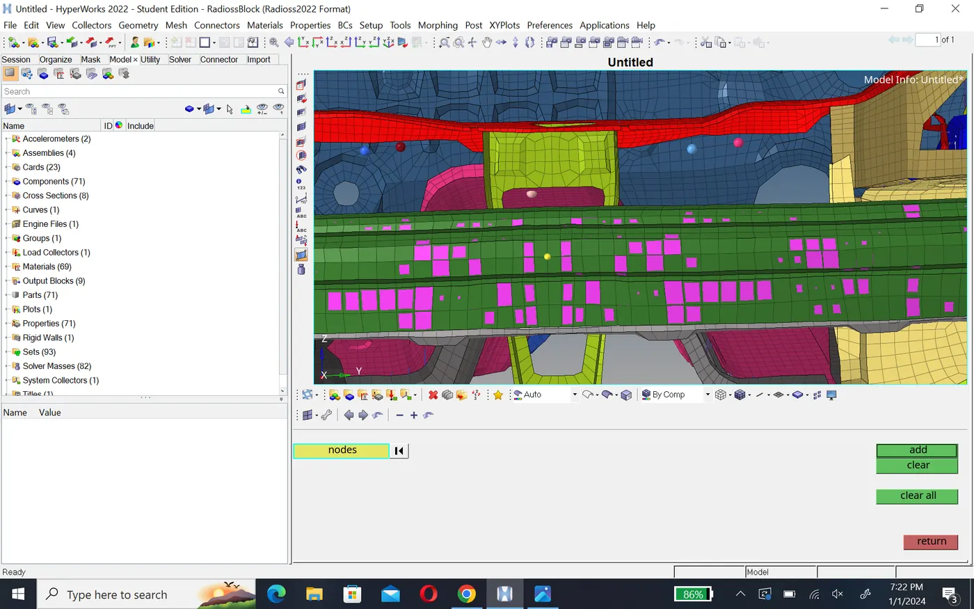
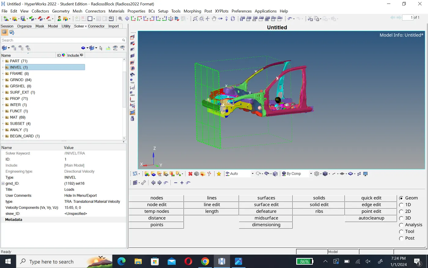
For the location of the rigid wall, we will click on the node which we create and then give a gap of 10 mm in x-axis i.e -1,0,0.Then we will specify the other parameter as follow.
Inital velocity:-
To create inital velocity,we will right click on the solver browser and then create BOUNDARY CONDITION >INIVEL card, we will select all the component as the entity for grnd_id . we will give the initial velocity of 35 mph or 15.65 mm/ms in x-axis and as the velocity should be translation velocity we will select TRA option in tpye
cross section:-
To create a cross section before we creare moving frames(solver>right click create >frame>mov) on a perticular node of that section these are called local axis, we want to perfect align our location axis to the global axis. so for this ,we will extract the node location of a particular node on the node section in nodes panel.then we will offset the node in x-axis by 10 units and create a now node similarly. we will offset and create a node in y-axis as show below.
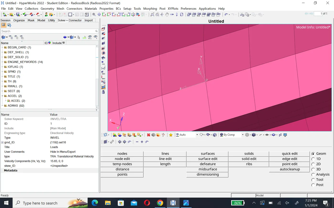
Now we create section right click on solver browser sect>sect. in section plane we will specify frame id and deltta value as 0.5 after that select shell element and create section.
similarly we will create cross section at the require part namely A-pillar, shotgun,or fender,bracket, and rail. These cross section will be created at both the sides as show below.
After creating cross section, we will request the result in TH(time history ).for this we will create output blocks under model browser.right click >output blocks >in this under entity ids option select cross section that we create then we will able to plote graphs of the cross section in hyper graph.
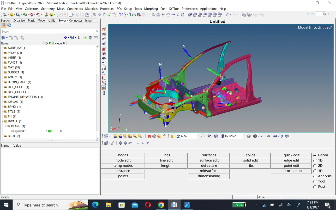
in the same way we will create the output block for every cross section.
Accelerometer :-
we have to measure acceleration of B-pillar during the crass. so we will create accelerometers on both the B-pillars. To create the accelerometer on B-pillar right click on solver browser>create >accel. then in node id select the node on B-pillar where we want to acceleration result and specify f-cut value as 1.65.
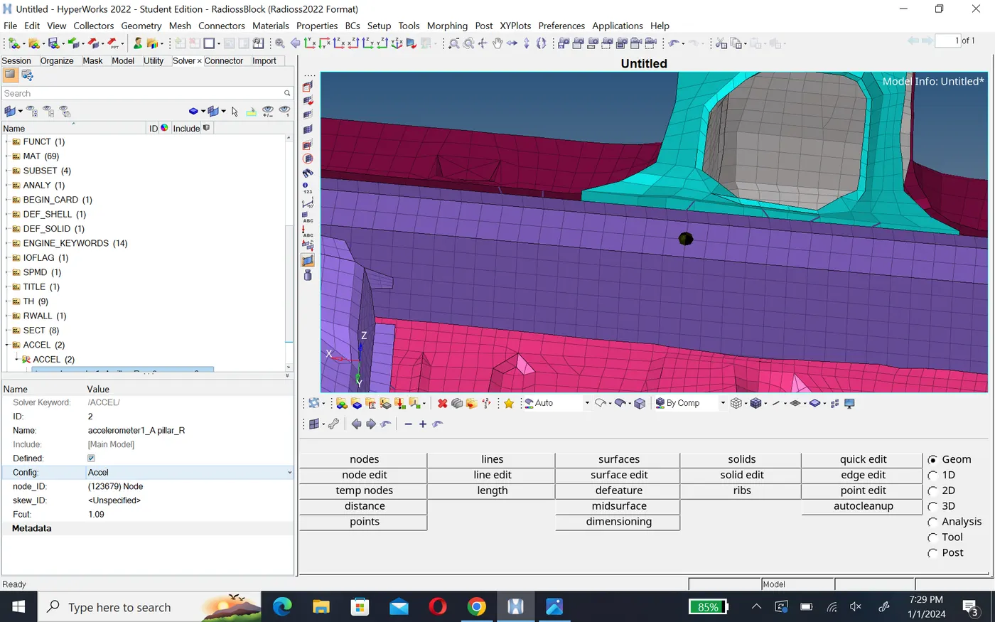
similariy we will create another another accelerometer on B-pillar . then we will create output block for accelerometer in the same way as we did for the cross section to request time hestory result.
Intrusion:-
Here we need to find the intrusion on the dash wall at nodes 66695 and 66244 respectively.so to find the results at the specifid nodes,we need to have a frame of reference. thes we will create moving frame at seat reinforcement part which shown below.
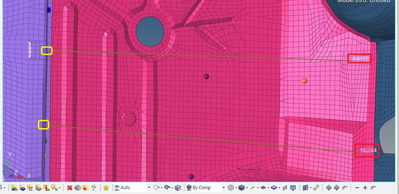
and connect these through the spring element.
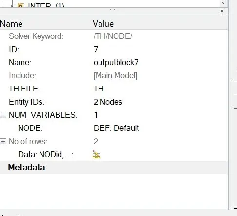
Then to obtane the results in Hypergraph,we will create output block for the intrusions by specifying the node and frame or skew based on which the intrusion are calculated.
Mass addition and balancing (mass-700 kg):-
First we will check mass and CG of the vehicle. for better visualization, we will use Hypercrash software to check the mass and CG of the vehicle.
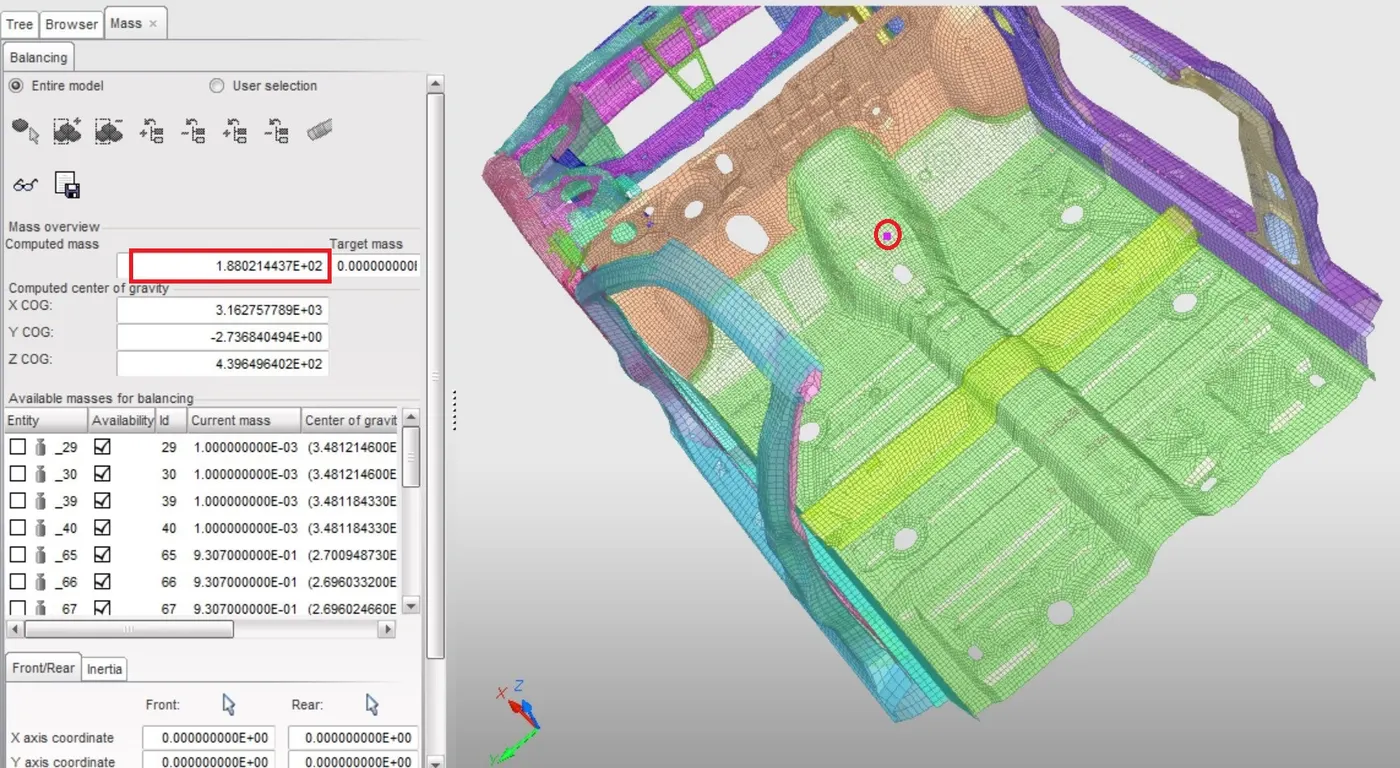
In the above picture, we can see the mass of the vehical is 188kg and cg of the vehicle is at the black circle.in gernal the cg of the vehicle is somewhere just behind the driver's seat.So in order to get the required cg location, we will do mass balancing by adding some on the panel where the passenger seat are located. We also have to get the mass of the vehicle to 700kg. So in Hypermesh, under solver browser, we will right click and create>admass. In admass panel,we will specify required mass to selected nodes and for mass type, we will select mass/nodes options.
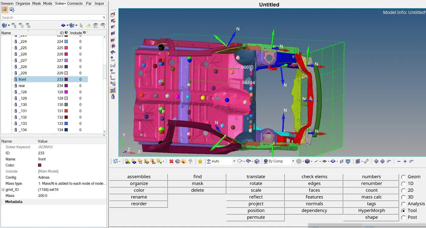
In this way,we will create rear_mass and front_mass and balance them to get 700kg and cg at required position. Since this model is not complete vehicle model. so that we will not concentrate much on the z-axis of the cg point and we will get cg below the floor panel as show below.
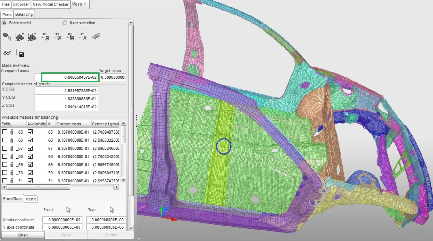
In the above figure, we can see the total mass of the vehicle 700 kg.
Time step and run time :-
To check these parameters in Hypermesh, we will open cards in solver browser to check the run time we will open ENG_run card where we will see that the model already have the run time in Tstop as 80ms. for the time step, we will open eng_dt_noda card and we will change the Tmin value to 0.5 microseconds or 0.0005 ms.
Model checker:-
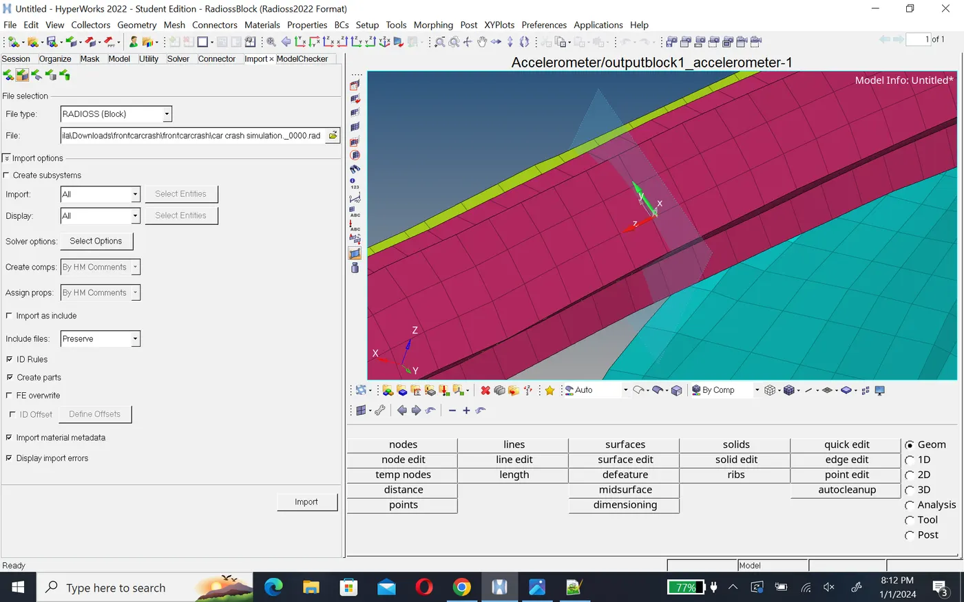
To check the quality of the model in the Hypermesh in meanu bar we will go to tool>model checker>radiossblock .This will open a new model checker browser.
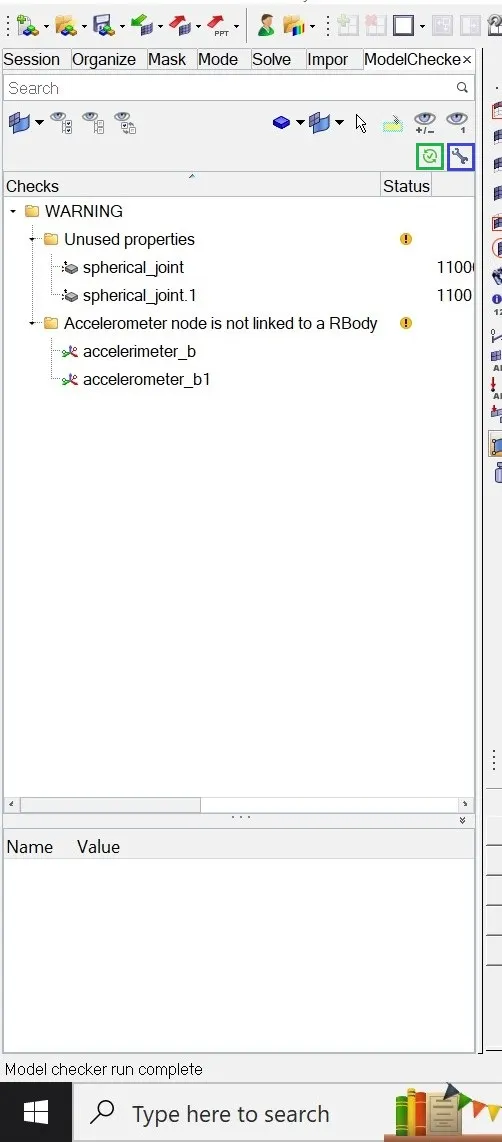
in this browser we will click on run checks commends which is at the top right side in the above figure,indicate green wright check .After runing the checks, we will click on Auto correct commends which is look like a wrench.And run simulation through tne radioss.
Simulation and result:-
To check energy error and mass error,we open the engine .out file of the model and check last for the energy and mass error as shown below.
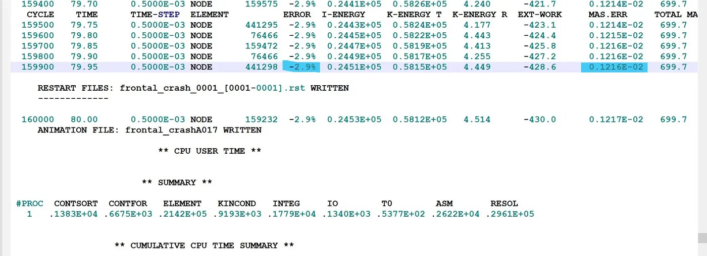
Energy error -2.9% and mass error 0.1216e-02 which is very negligible.This shows that the energy and mass error are within acceptable range.
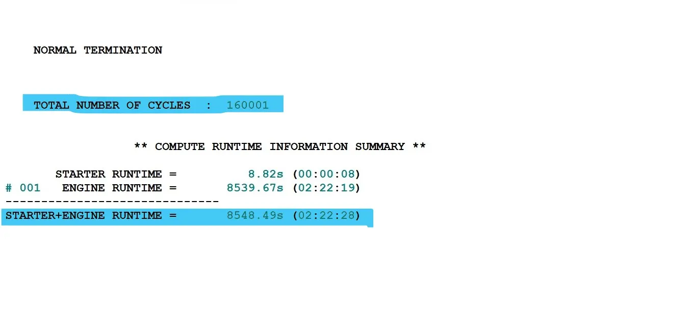
The total number of cycle 160001 and the total run time of the simulation is 8548.49s.
To view the simulation result we will switch hypergraph.In hypergraph we will load .h3d file and we will play the simulation.
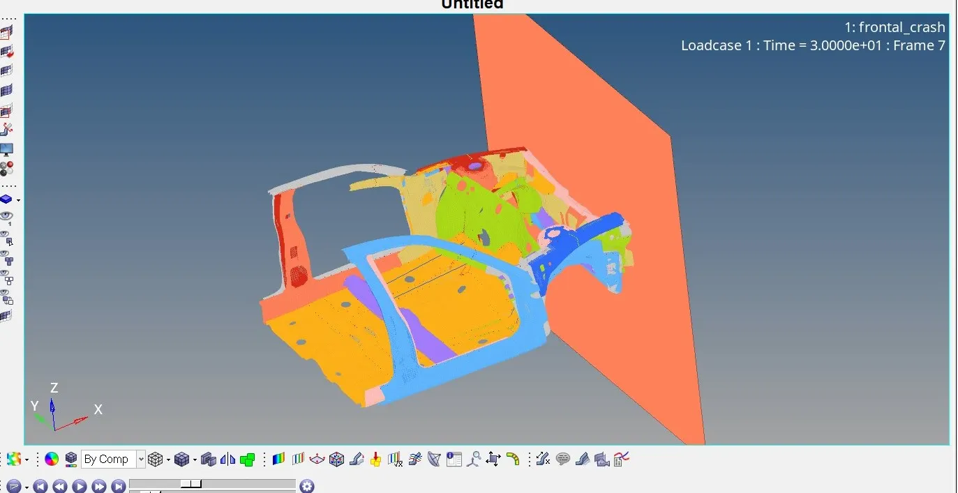
In the above simulation we can see the vehicle body impacting on rigid wall. After the impact the frame of the vehical deforme and vehicle and the vehicle has pitching movement about it's cg point. This model not a complete model so the deformation is unrealistic
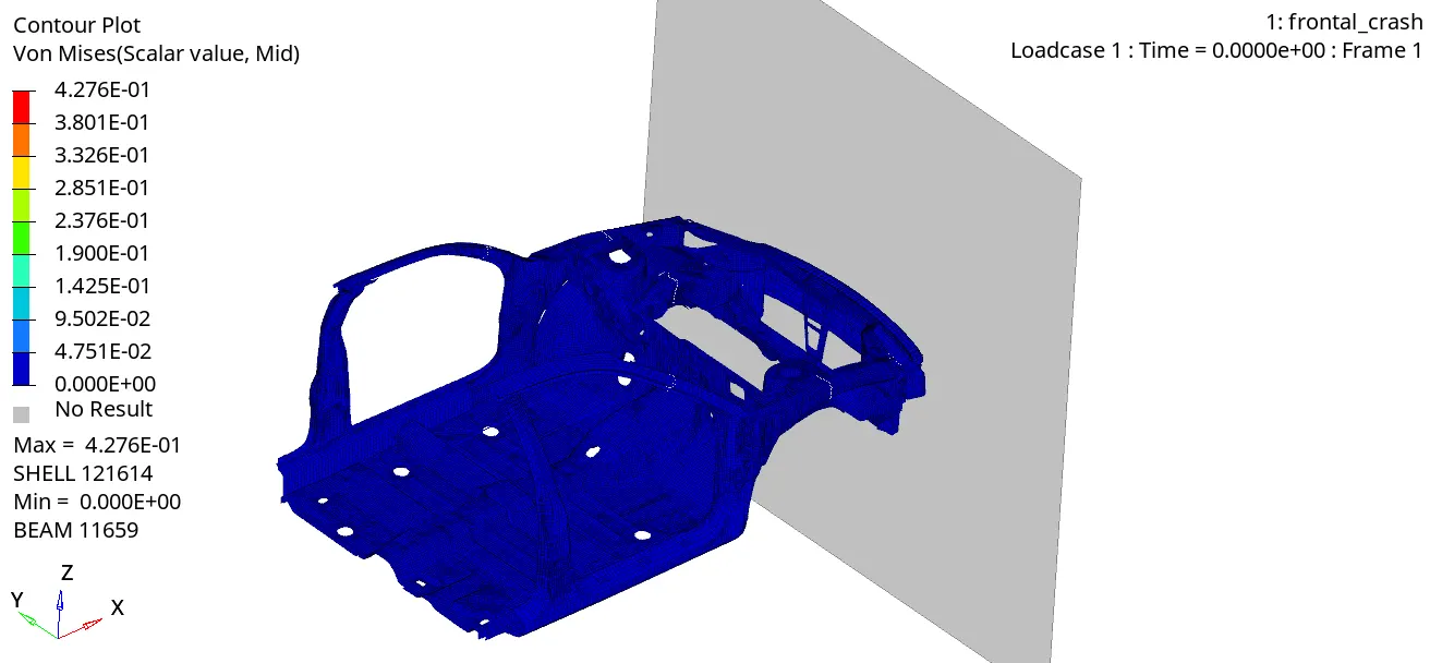
Frome von mises stress polt, we can say that the stress distribution is quite good in the vehicle after crash.Generally the stress is more in demping region as it is the first point of impact.
Energies:-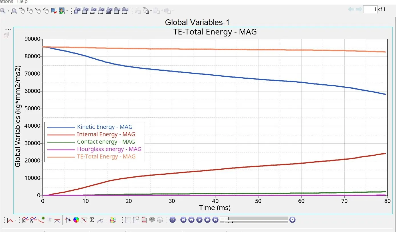
forme above graph we can see that there is high amount of kinetic energy at the start of simulation but as the simulation progress this energy decreases and after some time it convert into internal energy and internal energy increase in the same proportion. then total energy in the system constant at 85000J and due to some energy losses which we can see in the energy error, there is some decrease in total energy. we can also see some amount of contact energy in the modlel as we have defined the value of friction in type 7 interface due to this contact energy is generated.
cross section force
A-pillar: here section-a is left piller and section-b is right piller
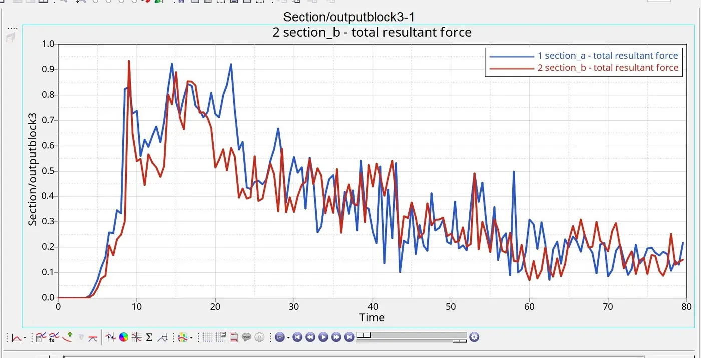
frome above plote we can see that reseltant force experience on the both same but at left piller force a littel bit more as compare to right piller.
Shotgun: here section-g1 is left shotgun and section-g2 is right shoutgun
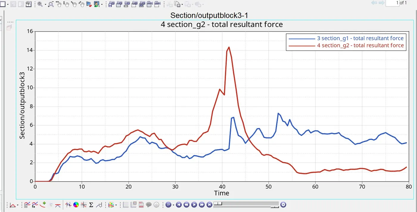
frome above plot we can see that initially resultant force experience on the right shotgun was higher but as the simulation progress it goes higher. instade of it force at left shotgun is lower as comparison to right.
Bracket: here section-b1 is left bracket and section-b2 is right bracket
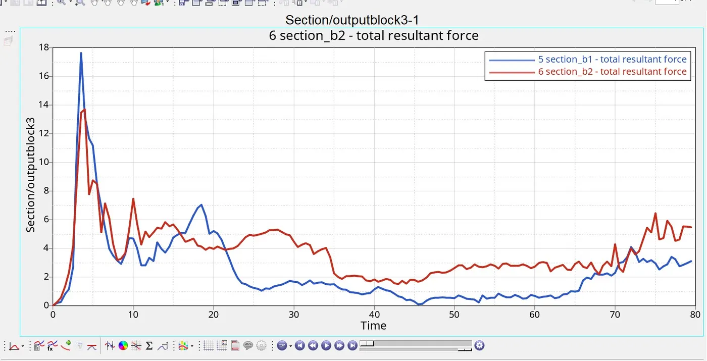
forme above plot, we can see that the reseltant force on the left bracket was higher than right bracket as simulation progress resultant force be more at right bracket and it remanes higher till the end of simulation.
Rail:here section-r1 is left rail and section-r2 is right rail.
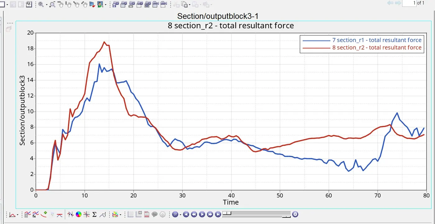
frome above plot, we can see that initially resultant force experienced on right rail as the simulation progress it goes higher value and it more than left rail.
Accelerometer:
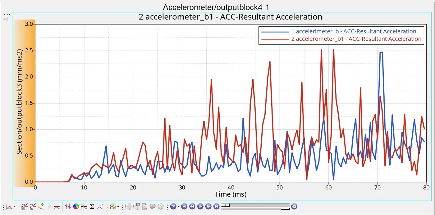
initially, accelerometer at both piller same after 6-7ms it grow up and here accelerometer of the left b1-piller was higher it remain higher till the end of the graph maximum value of the left b1-piller is 2.5ms and it same for right b-piller.
intrusions:
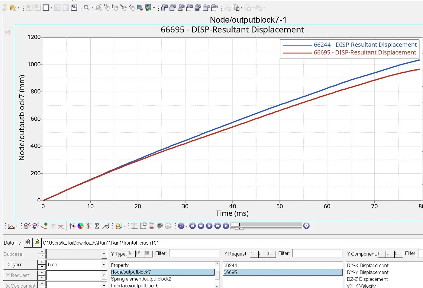
The resultant force displacement at node 66695 is900mm and the displacement of the node 66244 is some thing 1100mm. we can see more displacement at node 66244.
Conclusion:
The vehicle model impacted on rigid wall to study the frontal crash scenario of the vehical. As the model is reduced to limited parts, we get unrealistic deformation and results. Thus the center of gravity of the vehicle along with vehicle mass is very important and it mainly decides the behavior of the vehicle under crash.