Assignment 6-Frontal Crash Simulation Challenge
Assignment 6-Frontal Crash Simulation Challenge
Aim: Frontal crash simulation of given neon model by using hypermesh/Hypercrash and radioss.
Objective:
frontal crash-BIW
- Check unit system and either follow[Mg mm s] or [Kg mm ms].
- Create appropriate interface ,friction 0.2 and recommended parameters.
- Make sure of no penetrations and intersection.
- Correct rigid bodies if any issues.
- Create rigid wall with friction 0.1.
- Compare the model weight with the full scale 300k nodes model and use added masses to reach target weight 700kg while getting CG about the required range.
- Initial velocity 35 mph.
- Use model checker to ensure good quality.
- Time-step :0.5 to 0.1 microseconds.
- Run 80 ms.
Output requests:
- Sectional force in the rails at location of indicated node.
- Axial force received on the rails from bumper.
- Shotgun cross sectional forces.
- A pillar cross section.
- Acceleration curve received on the accelerometer at base of B pillar (on B pillar rocker).
- Intrusions on the dash wall 66695,66244
Procedure:
- Check the unit system
Open the neon_front_0000.rad file in the notepad from the downloaded files or to the begin card from the cards menu
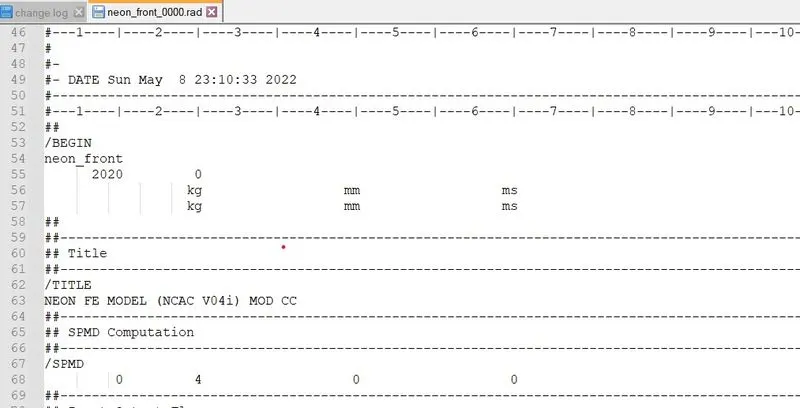
As from the screenshot it is visible that the unit system here is kg, mm, ms, we need not to make any changes.
- Creating an appropriate interface with friction 0.2 and the other recommended parameters
1) The most suitable type of interface to be created for this scenario is type7, which addresses the nodes to surface interactions.
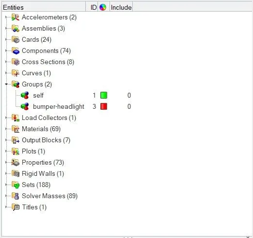
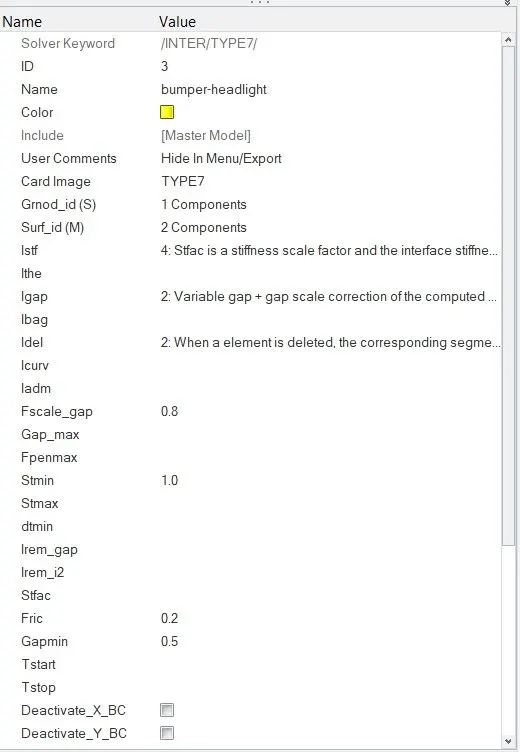
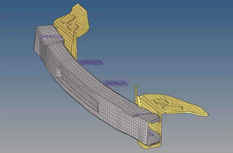
2)And we would also give a contact between bumper and headlight brackets.
- Checking for penetrations and intersections and eliminating them if any
1) The penetrations for the given model in hypermesh can be checked through the check penetrations option in tools section from the toolbar.
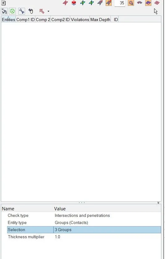
2) The penetration checker reports that there are no penetrations found, so there is no need to make any further changes regarding the penetrations and we can proceed to the next step.
- Correct rigid bodies if any issues
No issues were found with any of the rigid bodies.
- Create a rigid wall with friction 0.1
1) A rigid wall can be created with by using create option and selecting plane option from the rigids menu.
2) A proper node has to be provided as the reference, which forms the basis for the creation of the rigid wall.
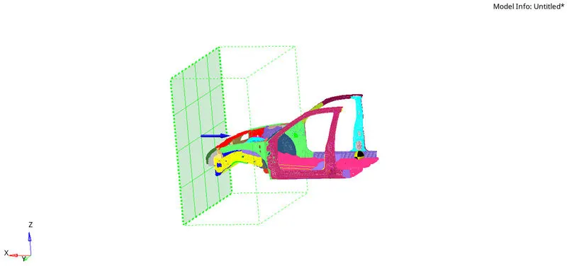
3) By double clicking on the created rigid wall, we can specify certain parameters which consist of friction as one of them and it is to be assigned a value of 0.1 along with an appropriate dsearch value.
- Compare the model weight with the full scale 300k nodes model and use added masses to reach target weight 700kg while getting CG about the required range.
1) Identifying the centre of gravity and adding masses to bring it within the acceptable range could be performed using the mass balancing option from hypercrash.
2)The starting model has a weight of 188kg and mass can be added to it, till it becomes 700kg.
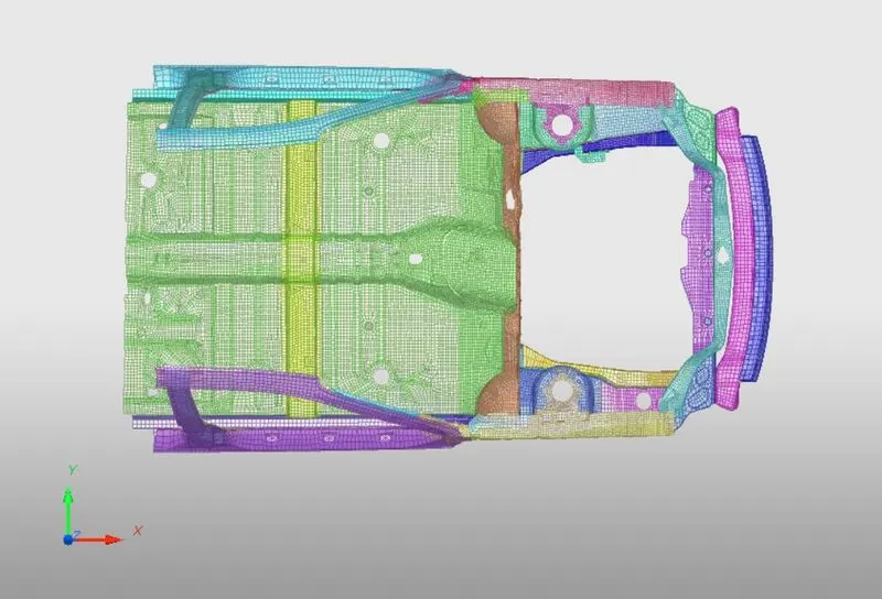
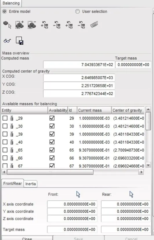
3) The mass can be added by picking a group of nodes and giving an appropriate value and also selecting the option of mass being distributed among the number of nodes selected.
- Provide an initial velocity of 35Mph to the model.
1) Using the create option, select the load collectors option and pick the inivel option.
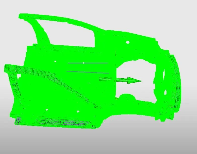
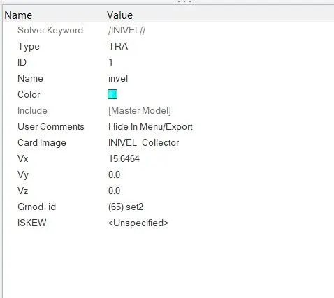
2) By clicking on the newly created inivel load collector, provide a velocity input of 15.64 mm/ms in the translational x direction.
- Use model checker to ensure quality
1) In hypercrash, the model checker can be found in the quality option from the toolbar.
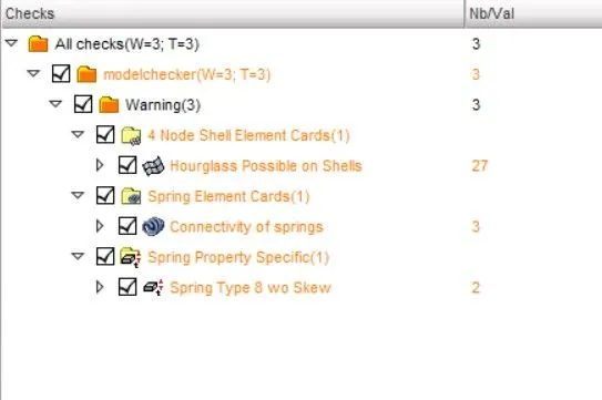
2) On running the model checker, a few warnings pop up without any noticeable errors. A few temp nodes which were responsible for the warnings were removed.
- Time step 0.1-0.5 microseconds
1) From the solver, The DT option enables us to view or edit the minimum time step.
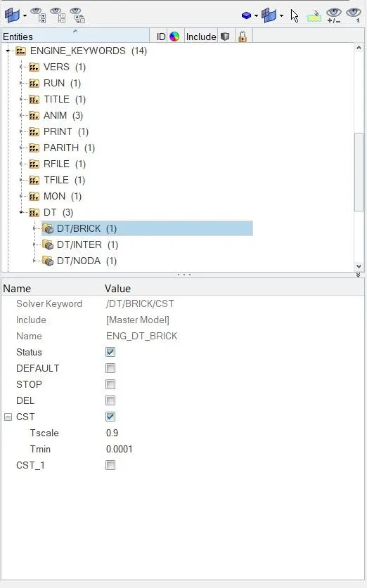
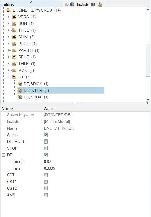
2) The nodal, elemental and brick time step can be edited and set as per the required specs.
For placing the output requests, certain entities have to be created in advance, they include
- Creating a section at the node 174247
1) The node can be located by using the serach node option in the hypercrash.
2) From the create new option and section menu a default section can be created at the specified node.
- Creating a section on the front bumper
1) The same default section can be used to create a section on the front bumper by selecting the 3 node option and picking any 3 consecutive nodes around the crossection.
2) The created section will be shown as elements with nodes on one side of them.
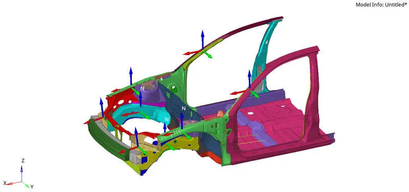
- Creating sections to measure forces and displacements at both A pillars, shotguns and front rails.
1) At each of the A pillars, shotguns and the front rails, similar to the previous cases the 3node option in the default section selection.
2)A proper set of 3 consecutive or non-consecutive nodes to avoid any irregular selection of the section.
3) The section selection is accompanied by the formation of a skew or a local co-ordinate system.
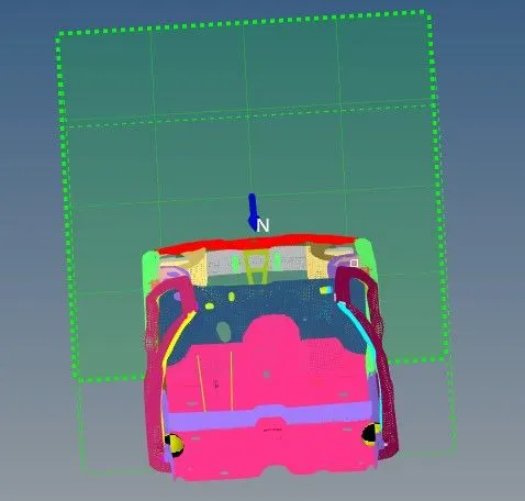
- Creating an accelerometer at the base of B-pillars
1) An accelerometer can be easily created by using the create option and picking the nodes at the respective bases of both the B-pillars.
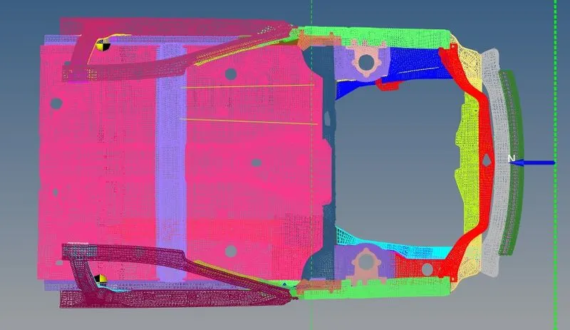
14.Intrusions on the dash wall at nodes 66695,66244
1) Two springs of very less stiffness have to be created from each of these nodes to any other base node to record the intrusions.
2) The springs can be created using grspring option and opting for 2N spring and a minor stiffness and a very little mass are assigned so that they do not interfere with the dynamics of the simulation.
After that we are going to create time history files
- For additional information like accelerometer data, sectional forces and intrusion of springs first we are going to create a time history file for necessary interfaces that were newly created
- Then we create acceleration time history file for accelerometer data.
- We create spring and RWALL time history files for intrusion and rigid wall forces
- We need sectional forces for the newly created sections, so for that we also give section time history file.
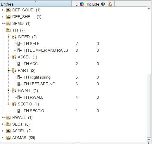
Then we run the analysis in radioss for getting the output files.
First, we open the 0001.out file to observe energy and mass error and other.
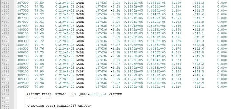
As we can see we are getting a -2.2% of energy error which is withing the range of -15 to 5% of energy error and is acceptable. And mass error is 0%.
The total runtime was 10782s.
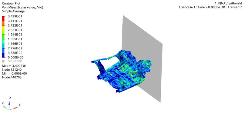
From the von mises stress plot, we can say that actually deforming In an unrealistic manner an stress is distributed in a good way.
Energies:
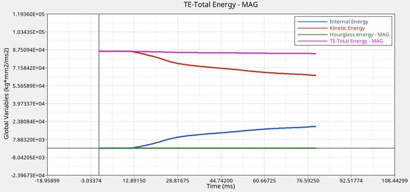
When the car crashes into the rigid wall, the vehicle starts deforming the internal energy increases as the surrounding energies are absorbed and as there is velocity at beginning of crash kinetic energy is high and as the velocity will eventually decrease kinetic energy will drop own to zero.
Hourglass energy is negligible due to using QEPH formulation.Contact energy is also very small as we have defined some friction in the interface.
Due to opposition forces while deforming the contact energy kept on increasing.
Rigid wall forces:
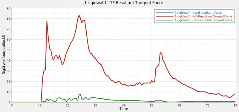
Here normal force, frictional force and total resultant force was plotted
As we can see the normal and total resultant force appear to be similar.
Sections:
FRONT RAILS
- A Section is made at the suggested nodes in the front rails two get the resultant force due to the crash through that section
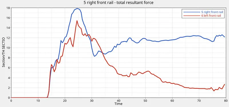
- From the above graph we can see the maximum force is at around 24ms which is 18kN
- we can see unequal deformation at rails which might be because of weight distribution and components
SHOTGUNS OR FENDERS
- A section is made at both the shotguns of the model
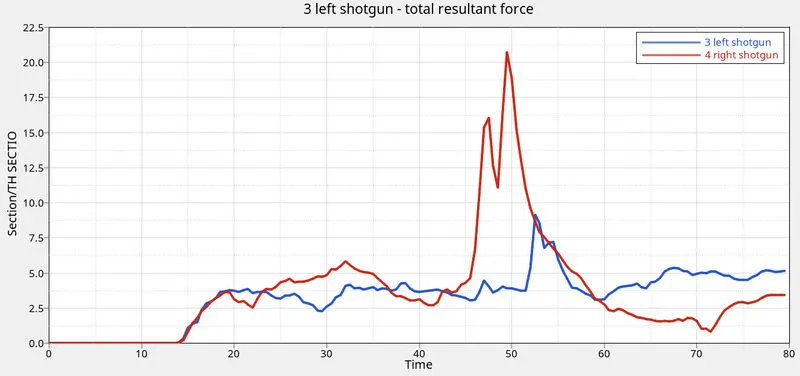
- A maximum force of 21kN i noted at the right shotgun while the left shotgun is 10Kn
- once again we can see unequal resultant forces
A PILLERS
- A section is made at the recommended point in the A piller
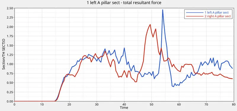
- A maximum resultant force of 2.5KN is oborved in the left A piller, while the right A pillar was 2KN
- here the left piller had more force applied on it than right piller
BUMPER INTERFACE
- A type 7 interface is made between the bumper and the front headlight rail to check the axial force applied by the bumper on the rails
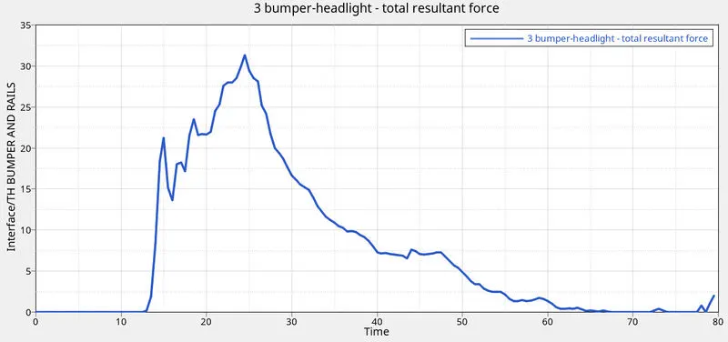
- Here we can see a maximum of 32KN of axial force is transmitted by the bumper on to the rails
- The resultant force slowly drops until all the mometum due to the velocity is reduced
INTRUSION
- The compression experienced by the springs gives us the intrusion on the selected components

- We can see as the time increases the intrusion in the selected nodes keeps increasing due to the deformation
- Giving more time only increases the intrusion by even more
ACCELOMETER
- An accelometer is kept at two ends of A piller
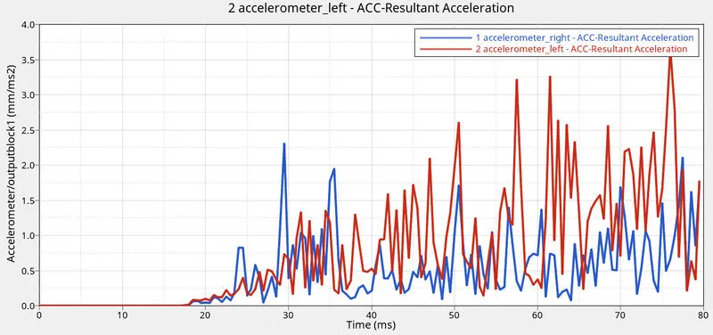
- We can see huge spikes after initial collision and spikes keep increasing as the collison progresses
- The graph shows the acceleration of the selected node during the collison
- we can see accelometer at left reached a value of 3.5m/s2
CONCLUSION
- Got a clear understanding of how to apply varies conditions on large models
- Understood how to apply sections and find forces in a particular component
- found out how to find intrusion in selected components
- Got to know how to add an accelometer and get the data
- Understood the importance of spring elements
- Got to know how to find out the cog and how to add mass to change the cog