Assignment 6-Frontal Crash Simulation Challenge
 OBJECTIVES
Frontal crash-BIW
- Check unit system and either follow[Mg mm s] or [Kg mm ms].
- Create appropriate interface ,friction 0.2 and recommended parameters.
- Make sure of no penetrations and intersection.
- Correct rigid bodies if any issues.
- Create rigid wall with friction 0.1.
- Compare the model weight with the full scale 300k nodes model and use added masses to reach target weight 700kg while getting CG about the required range.
- Initial velocity 35 mph.
- Use model checker to ensure good quality.
- Time-step :0.5 to 0.1 microseconds.
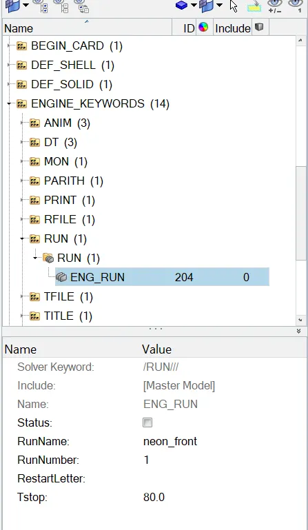
- Run 80 ms.
Output requests:
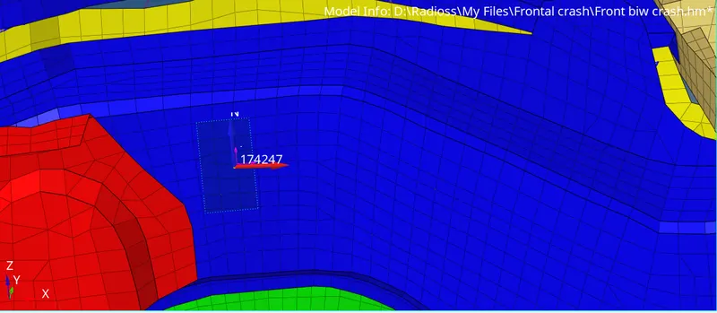
- Sectional force in the rails at location of indicated node 174247.
- Axial force received on the rails from bumper.
- Shotgun cross sectional forces.
- A pillar cross section.
- Acceleration curve received on the accelerometer at base of B pillar (on B pillar rocker).
- Intrusions on the dash wall 66695,66244
PROCEDURE
In this challenge we have to perform a frontal crash simulation for the car BIW part. So that we have to perform all the checks given and plot ehe output graphs.
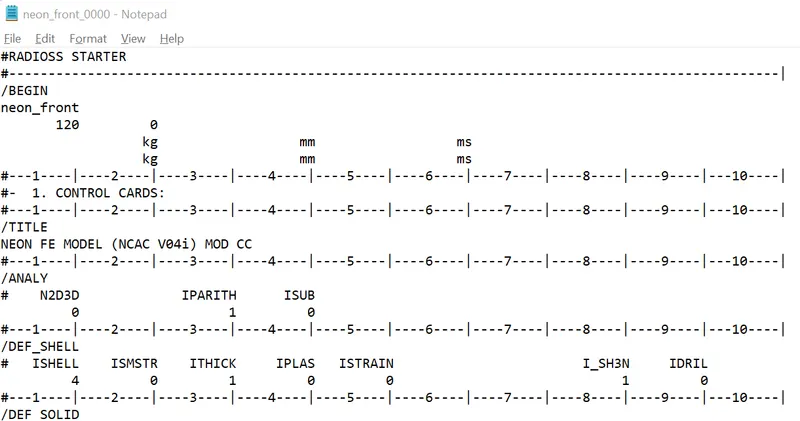
Check unit system and either follow[Mg mm s] or [Kg mm ms].
Now we will check the unit system for the model. To check open the 0000.rad file.
Create appropriate interface ,friction 0.2 and recommended parameters
here we need to create a type7 contact interface with the recomended properties.
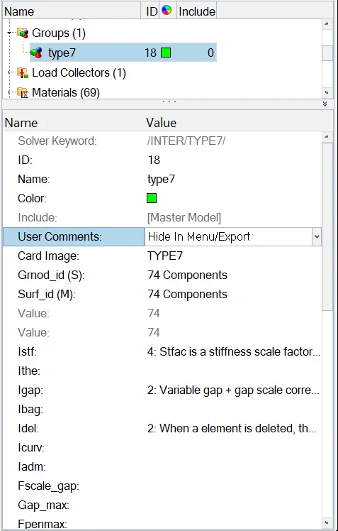
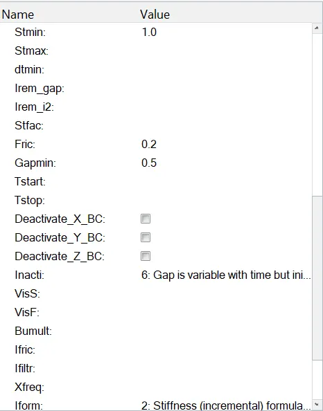
after the creation of type 2 contact, need to check for penetration and intersections.
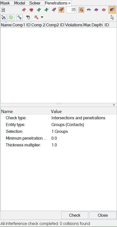
Make sure of no penetrations and intersection.
Now check penetrations and intersections in Quality-check all solver connection interface.
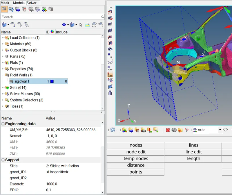
Create rigid wall with friction 0.1.
To create rigid wall go to SOLVER-CREATE-RWALL with the plane wall of friction 0.1
Compare the model weight with the full scale 300k nodes model and use added masses to reach target weight 700kg while getting CG about the required range.
Now we have the full model of the car that have 700kg and we have to compare those 2 models and equalise the weight throughout the front BIW.
Now to check the mass details go to TOOLS-MASS DETAILS-MASS & COG.
Here it will show the total weight and center of mass at certain node. So the COG of the node should be at the center of the rail.
To Create a mass go to SOLVER-ADMASS-CREATE.
While creating admass select nodes in random areas to manage the cog.
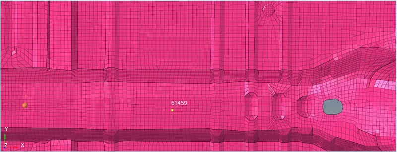
In this image there is node 61459 aligned a center weighted 700kg that showing at the center of rail component.
Initial velocity 35 mph.
To create initial velocity convert the 35mph to ms.
35ms=15.64m/s
To create a initial velocity go to BROWSER-BCS-INVEL. Then give the required values that shown in the image below.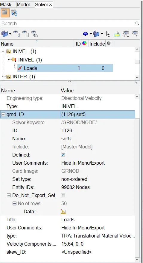
Use model checker to ensure good quality.
To check model quality go to TOOLS-MODEL CHECKER-RADIOSS BLOCK.
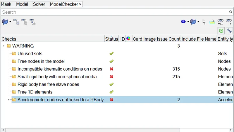
Here it shows some errors that can be corrected using auto correction.
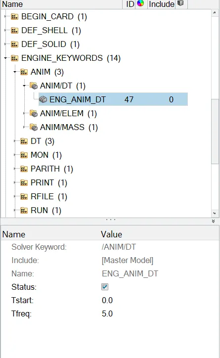
Time-step :0.5 to 0.1 microseconds.
To modify time step go to solver and ENGINEKEYWORDS-ANIM/DT. In the card image change it to 5.
Run 80 ms.
Sectional force in the rails at location of indicated node 174247.
Here we need to create a section at the node 174247. Find that node using the TOOLS<NUMBERS<.
At that node we need to create a frame to define a section.
To create a frame go to BROWSER<CREATE
After creating a frame BROWSER<SECT.
Create a section at the same node Select entites and choose frame id in the card image.
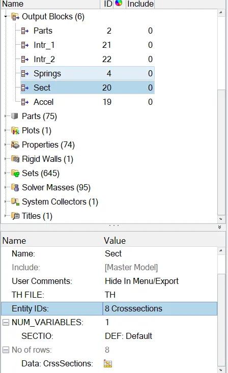
like the above same steps create all remaining output blocks.
Axial force received on the rails from bumper.
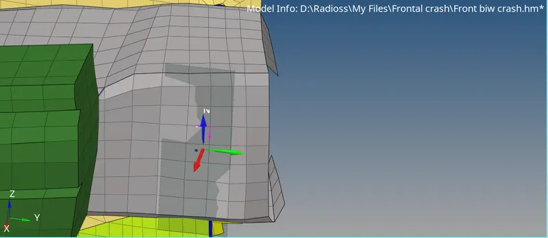
Shotgun cross sectional forces.
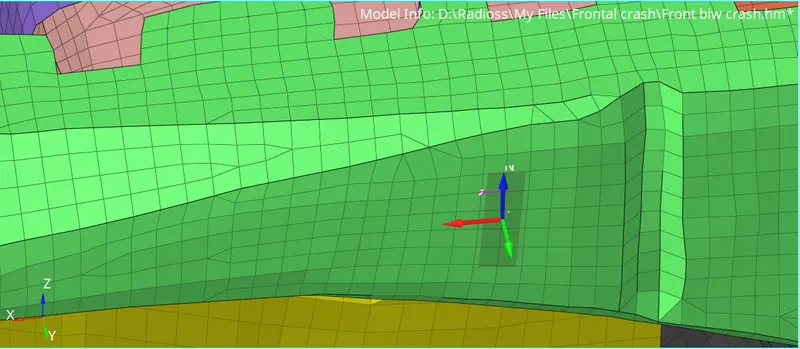
A pillar cross section.
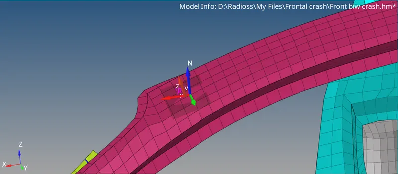
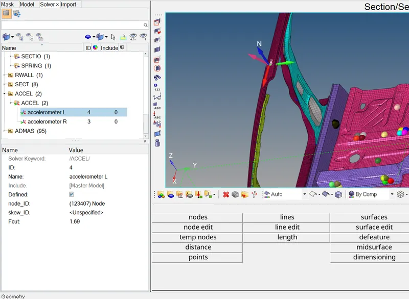
Acceleration curve received on the accelerometer at base of B pillar (on B pillar rocker).
Now create an accelerometer in the left and right Bpillar SOLVER<CREATE<ACCELEROMETER.
Intrusions on the dash wall 66695,66244.
Find the 2 nodes and create a intrusion and create a skew on the rail.
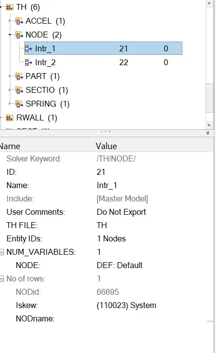
All the output blocks can be Created and add in output block card like the image below.
Now Run the simulation.
Open the 0000.rad file and examinate the cycles and energy and calculations.
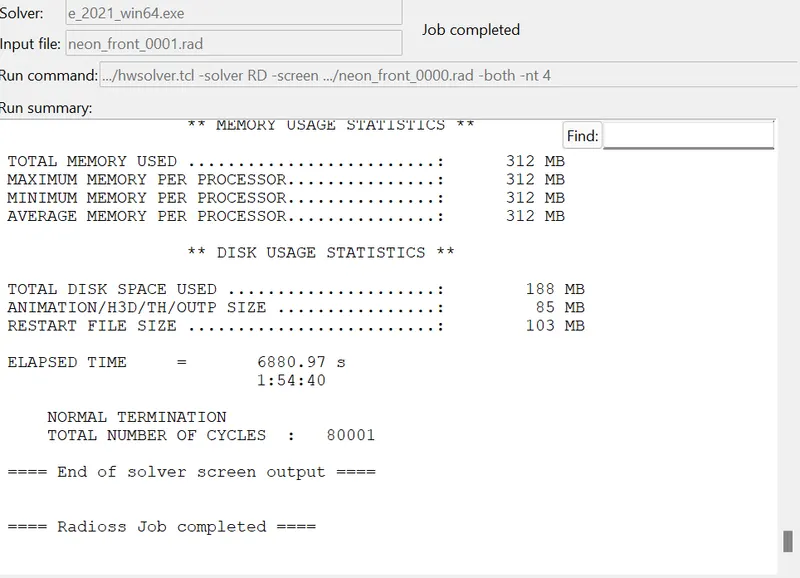
The Simulation Run normally and now we can proceed with animation.
Open Hyperview and import the h3d file.
Plot vonmises and select all the components and apply.
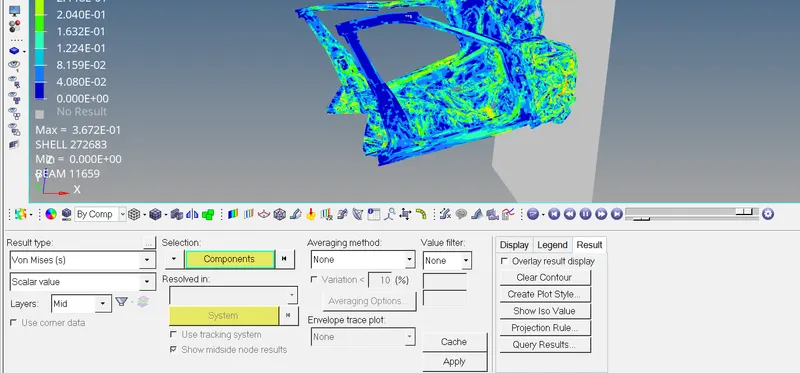
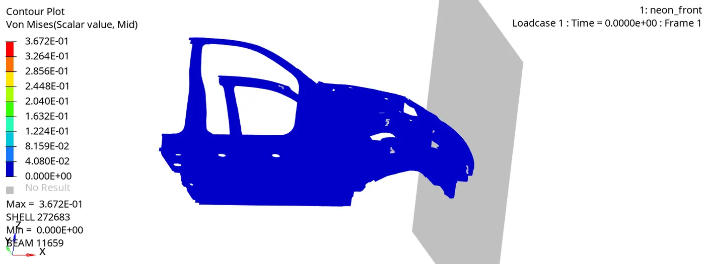
Now Open the Hypergraph and import T01 File and plot required energies and output blocks.
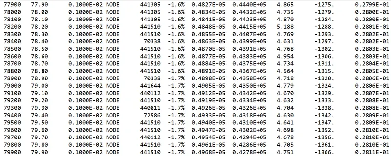
As we already see Solver ends normal termination and No of cycles is 79900.
The energy error is -1.7% which is still acceptable so that should between the -10% to +5%.
The mass error is 0.02811. Also the animation file can show that stress distribution in the component looks good after the crash.
POST PROCESSING-PLOTTING GRAPH
RAILS 1 & 2
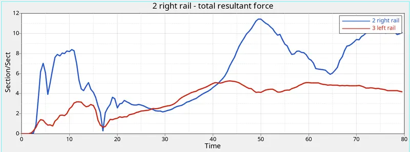
Here the Left rail have 5kN/mm and the other rail have peak 11kN/mm. So the resultant force differences are more.
BUMPER 1&2.
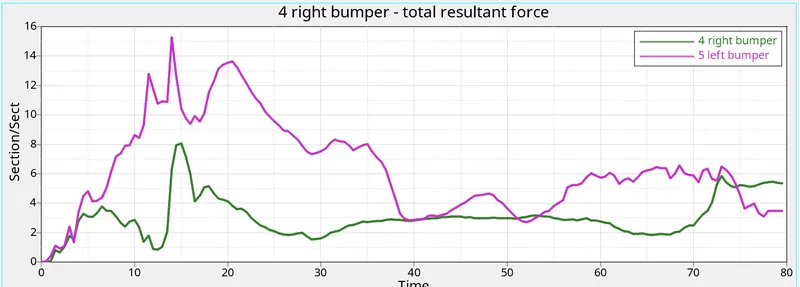
Here the peak stress of left bumper goes to 15kn in the 1st stage of 15ms and right have 8kn at the 1st hit in rigid wall at the same time interval.
SHOTGUN 1&2
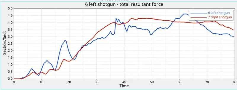
In this case both the shot gun 1,2 have the same level of stress in the same time interval as 4.7kn at left and 4.3 at right shotgun.
PILLAR 1&2
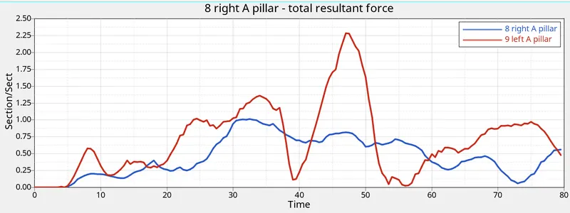
In this case the right pillar have peak of 2.26kn at 45ms and left pillar have 1kn at 32ms.
ACCELERATION.
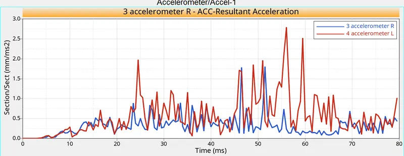
The acceleration looks somewhat same at both the regions.
Intrusion 1&2
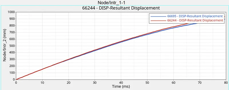
Both the displacement are looking same.
At finally plot the total energy, kinetic energy, Contact energy, Hourglass and internal energy.
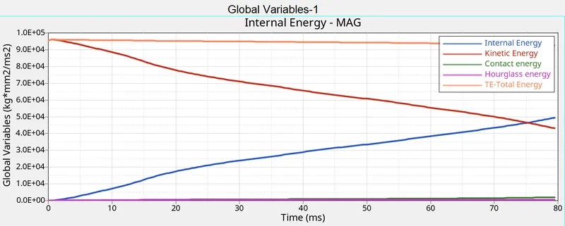
Here Hourglass is zero and all the remaining energies gradual it so fine.
Observation
In this case we created output blocks to check the stress deformation in every parts through the graph which can easily examine the results. Model checker and Admass cards are very useful in adding mass to the floor and model errors. With those animation we can predict some real time crash the we do with the prototype.
Here we can see the the stress at the 1st hit is peak and it travels through the rail, shotgun and the A pillar and remainings to the dash wall. when the shotgun and the A pillar gets deformed more the passenger may injure more even if it has air bag systems.
CONCLUSION
This model is created and added in simulation to check the crash senario in front BIW part. So the Engine cards and simulation, results and values are discussed in this challenge.