Assignment 6-Frontal Crash Simulation Challenge
Aim:-
- To perform the frontal crash on car model given and study about deformation and stresses developed in the model.
Objective:-
- First to check the unit system.
- Create type-7 contact with friction value 0.2 with recommended parameters.
- To check for penetration and intersections in the model if present.
- Check for the rigid body if any, means make sure all component connected properly.
- Create planer rigid wall with 0.1 friction value.
- Add mass on given body to reach target of 700kg and make COG align approximately with seat rail.
- Give initial velocity of 35mph(mile per hour) which is 15.6464 m/s in x direction.
- Give time step of 0.0001 for Brick Noda and Inter.
- Give run time of 80 ms in run card.
Request for additional TH output:
- Sectional force in the rails at location of indicated node 174247.
- Axial force received on the rails from bumper.Shotgun cross sectional forces.
- A pillar cross section.
- Acceleration curve received on the accelerometer at base of B pillar (on B pillar rocker).
- Intrusions on the dash wall 66695,66244.
Abstract:
A crash test is a virtual reconstruction that replicates the same force and speed that would occur if the vehicle was to be involved in an actual crash. In this type of testing, since nothing is physically impacting the body-in-white (BIW), no physical deformation or damage occurs to the body's structure, allowing multiple
crashworthiness tests to conduct in succession.
- Frontal crash test.
- Side-impact crash test.
- Roof crash test.
In this particular challenge, we will discuss the frontal crash,
Since in frontal crash test, there are multiple standards used on which we have to focus.
FMVSS 208-
- Federal Motor Vehicle Safety Standard 208 (FMVSS 208) regulates automotive occupant crash protection in the United States. Like all other Federal Motor Vehicle Safety Standards, FMVSS 208 is administered by the United States Department of Transportation's National Highway Traffic Safety Administration.
- This test procedure is used to determine whether a vehicle meets the conditions, requirements, and injury criteria specified in Federal motor vehicle
safety standard (FMVSS) No. 208, Occupant crash protection. - In this test, according to FMVSS 208, we give the initial velocity of 35mph(mile per hour)or 56km/h or 15.56m/s to the Car body.
Euro NCAP:-
- Euro NCAP tests cars against a rigid barrier with full overlap at a test speed of 50 km/h. A small female frontal impact dummy is seated in the front
driver’s seat and in the rear passenger side seat. - In this, we perform crash and we give initial velocity as 31mph(mile per hour) or 50km/h.
This test places high demands on the restraint systems in front and rears seating positions. Strict limits are placed on the decelerations of the chest and on
the degree of chest deflection and this, in turn, encourages manufacturers to fit more sophisticated restraints.
The test complements the offset deformable test as a balance must be found between a restraint system that is stiff enough to restrain a male dummy
in the frontal offset test and one that is compliant enough not to put injuriously high deceleration forces on a small female.
In this tets overall we make car structure stiffer, so it can help to reduce lower leg and head injury.
Procedure:
1. Check for units both in Hypermehs and Hypercrash.
2. Import the model in hypercrash.
3. Perform mass balancing in hypercrash.
4. Export model in hypermesh.
5. Give time step for Brick,Noda and Inter as 0.0001 milisecons with respective scale factors.
6. Check for initial penetrarion and intersection.
7. Give initial velocity of 35mph(mile per hour) or 15.6464 mps(meter per second).
8. Create type-7 interface contact with friction value as 0.2.
9. Create Infinite plane rigid wall with friction 0.1.
10. Create intrusion spring on dasboard position to measure the deformation.
11. Create sections on bumper,rails and A-piller.
12. Request for TH file as required for this challenge.
13. Perform model checker.
14. Run the simulation.
15. Post-processing
1.Check for units both in Hypermehs and Hypercrash:
Hypermesh
Go to Solver>cards>Begin card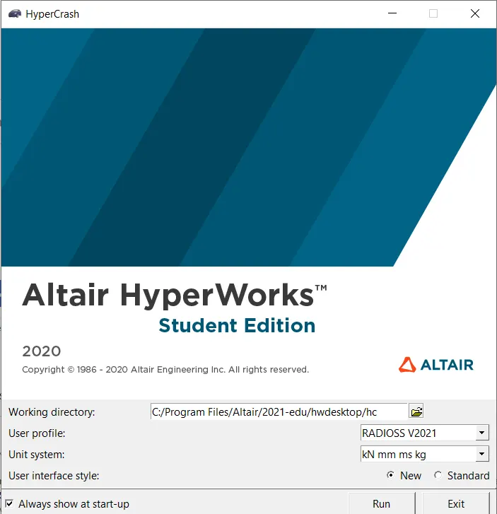
Hypercarsh:
In hypercrash while opening itself it will ask to select unit where we will choose as shown below.
2.Import the model in hypermesh.
Go to File> import>Import solver deck> select the file from folder.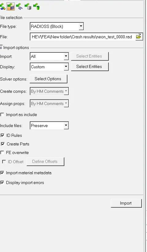
Import the model in hypercrash.
Go to File>import >Radioss>select the file from folder.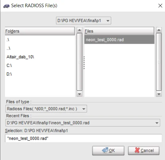
3.Perform mass balancing in hypercrash.
For mass balancing first we will check the initial mass of the model for that,
Go to Mass > Mass balancing , It will show the initial mass as shown below as 188.4 kg.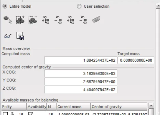
To reach to the mass value of 700kg we need to add 511.6 kg mass more.
For mass addition, we will use the ADMAS option.
For Add mass
Go to Load case > Added mass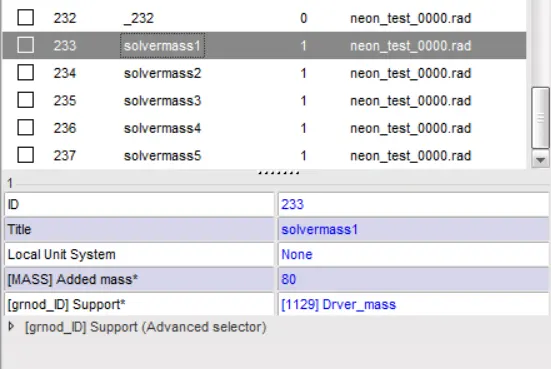
Similarly we will add mass over floor panel to reach 700kg mass.
And to place COG at right place on rail.
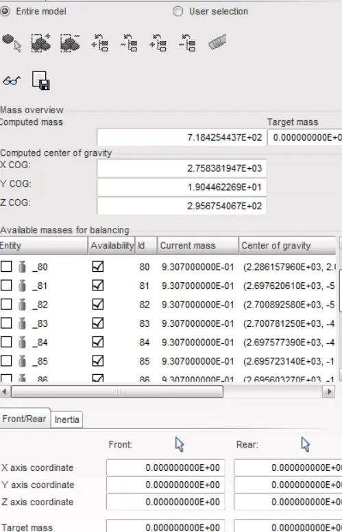
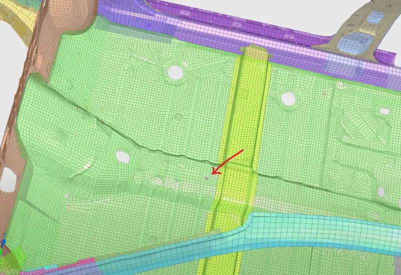
Now we can see the COG location and target mass as 700 kg.
5. Give time step as 0.0001 milliseconds with respective scale factors.
To give time step go to Model browser> cards > ENG_DT_BRICK
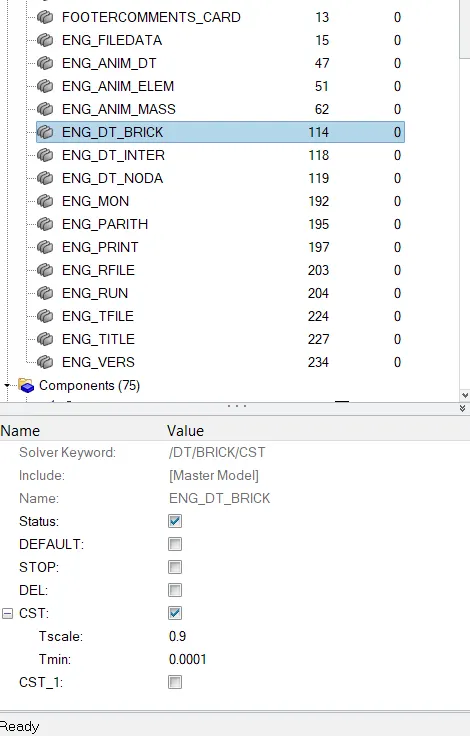
Give CST type and add value for scale factor and time step.
Simmilarly we will do for NODA.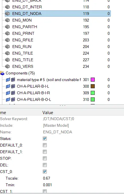
Now we will give the time step for the interface and we will choose DEL here.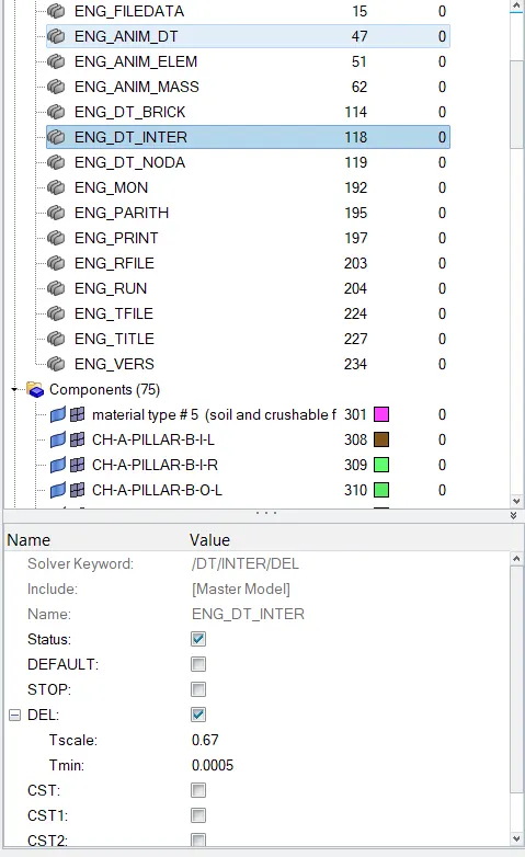
6. Check for initial penetration and intersection.
Here we will check for initial penetration in the model.
For that go to tool > Penetration check > Select group > Check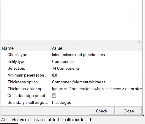
After selecting, groups, hit on check it will show the result below.
Here we can see that 0 collisions were found.
7. Give an initial velocity of 35mph(mile per hour) or 15.6 MPs(meter per second).
Create > Boundary condition > INVEL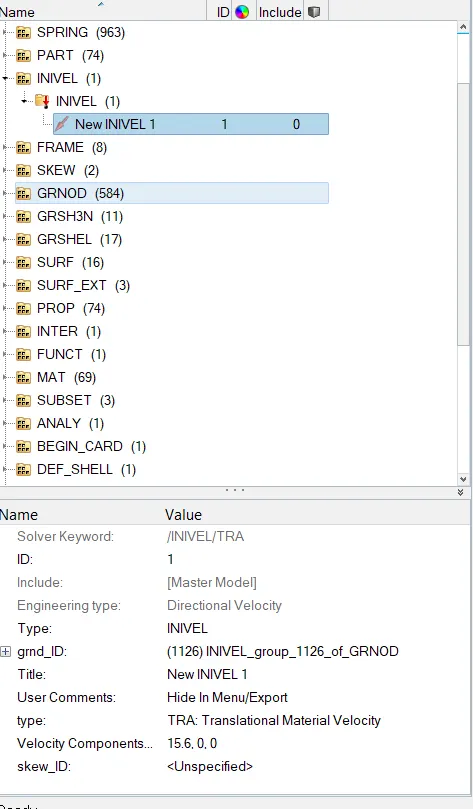
Now here in INVEL card give a velocity of 15.6 on the global x-axis.
Select all components because we are going to give the initial velocity for the whole BIW parts.
8. Create type-7 interface contact with friction value as 0.2.
Go to create > INTER > Type-7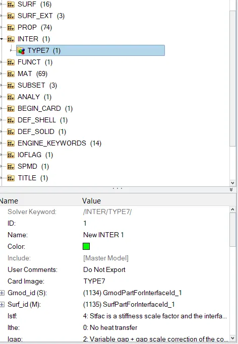
9. Create an Infinite plane rigid wall with friction 0.1.
Go to Create > RWall > Plane
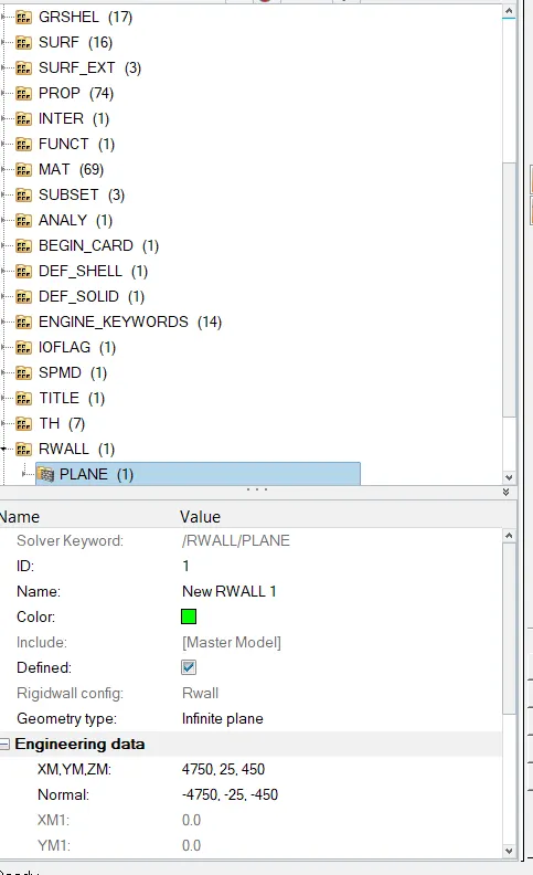
Infinite planner Rigid wall created now
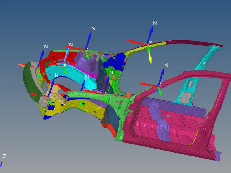
10. Create sections on bumper, rails and A-pillar.
we are creating sections to analyze the amount of force is travelling from that region.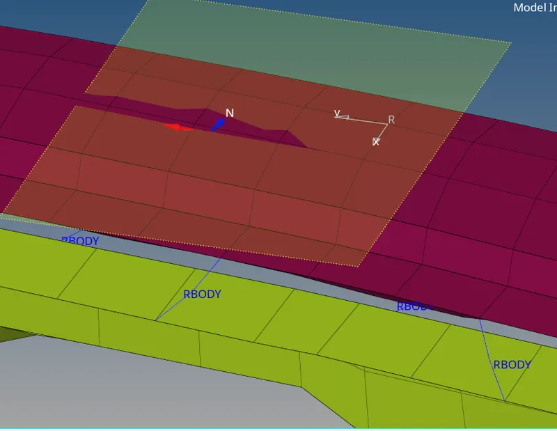
11. Output Request:
Create Accelerometer
We will request the TH file for the acceleration curve received on the accelerometer at the base of the B pillar (on the B pillar rocker).
For that First create an accelerometer,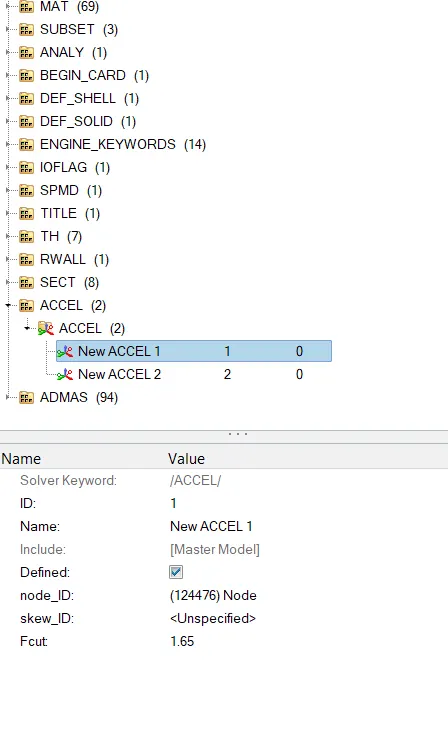
a).Now request for TH file for accelerometer,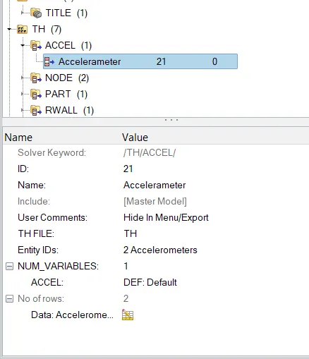
Now request for TH file for sections Select all sections we had created.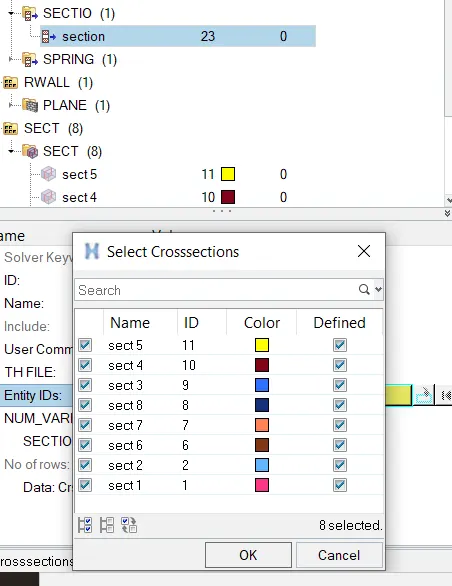
Now request for TH file for intrusion spring run the simulation:
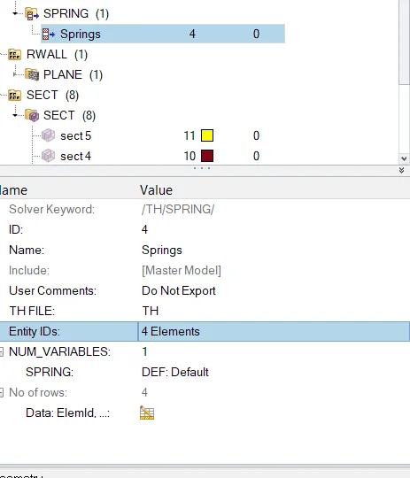
To run the simulation go to Analysis > Radioss.
After clicking Radioss click on input file and save it in new folder
Check the include connectors and option as -nt 4.
N indicated the how many cores will involve to run the simulation.
It will make simulation faster.
After that click on Radioss it will start the simulation.
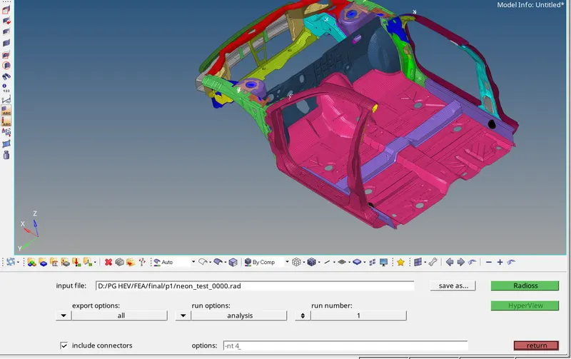
And wait until the new window popup show as Radioss job completed.
After running the simulation we will get the animation file, h3d file and also T01 file.
Check for all the files.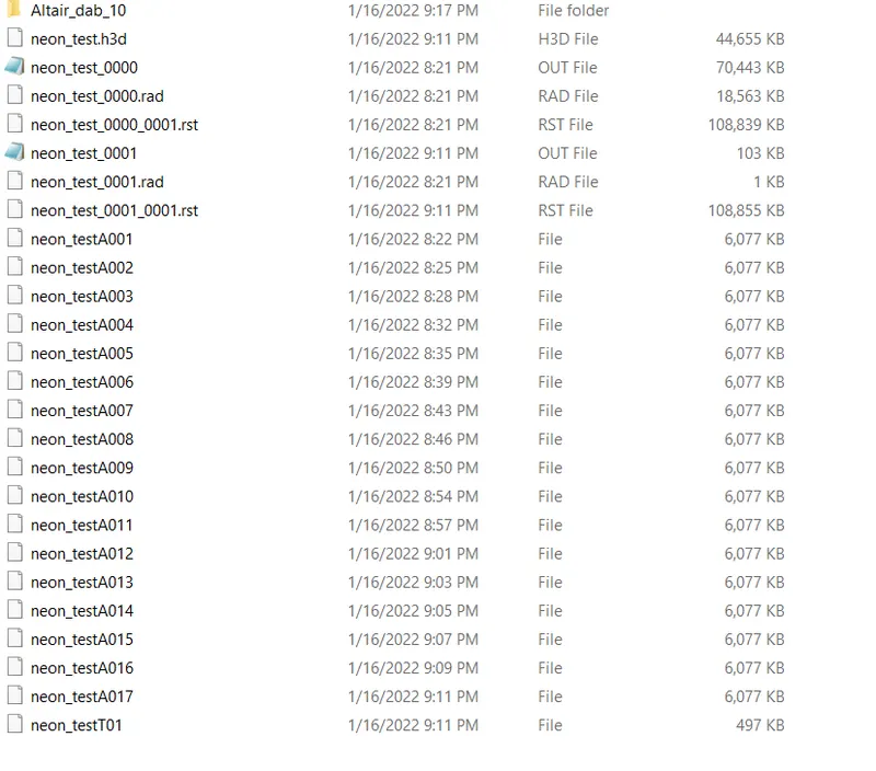
Now open 0001.out file and check all the details.
Here we can see all variables in the out file about energy error and mass error also.
So for checking the maximum loss check the last cycle details.
Here in last cycle of the simulation, we have maximum energy losses where,
Energy error = -1.2 % Acceptable (Range is -15% to +5%)
Mass Error = 0.2749E-01 Acceptable (Range is 0 to 2%)
So the resultant energies are,
1. Internal Energy 0.4066E+05
2. Kinetic Energy 0.4558E+05
3. External work -1282
4. No of cycles 79900
Post-processing reviews the simulation using Hyperview.
Plot the graphs using Hypergraph-2D
1. Review the simulation using Hyperview.
Split the screen in two parts now after splitting the screen open hyper view after switching into in 2nd screen.
In hypergraph, window import the h3d file for a simulation run.
Animation-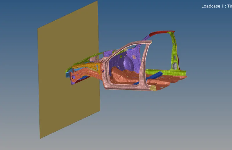
Now after importing the h3d file on hyper view GUI go for contour activation.
In contour, it will show the simulation graphically and contour lines of load and other properties variation.
To activate contour go to Toolbar > contour as shown below.
Go to Contour > Displacement > apply contour.
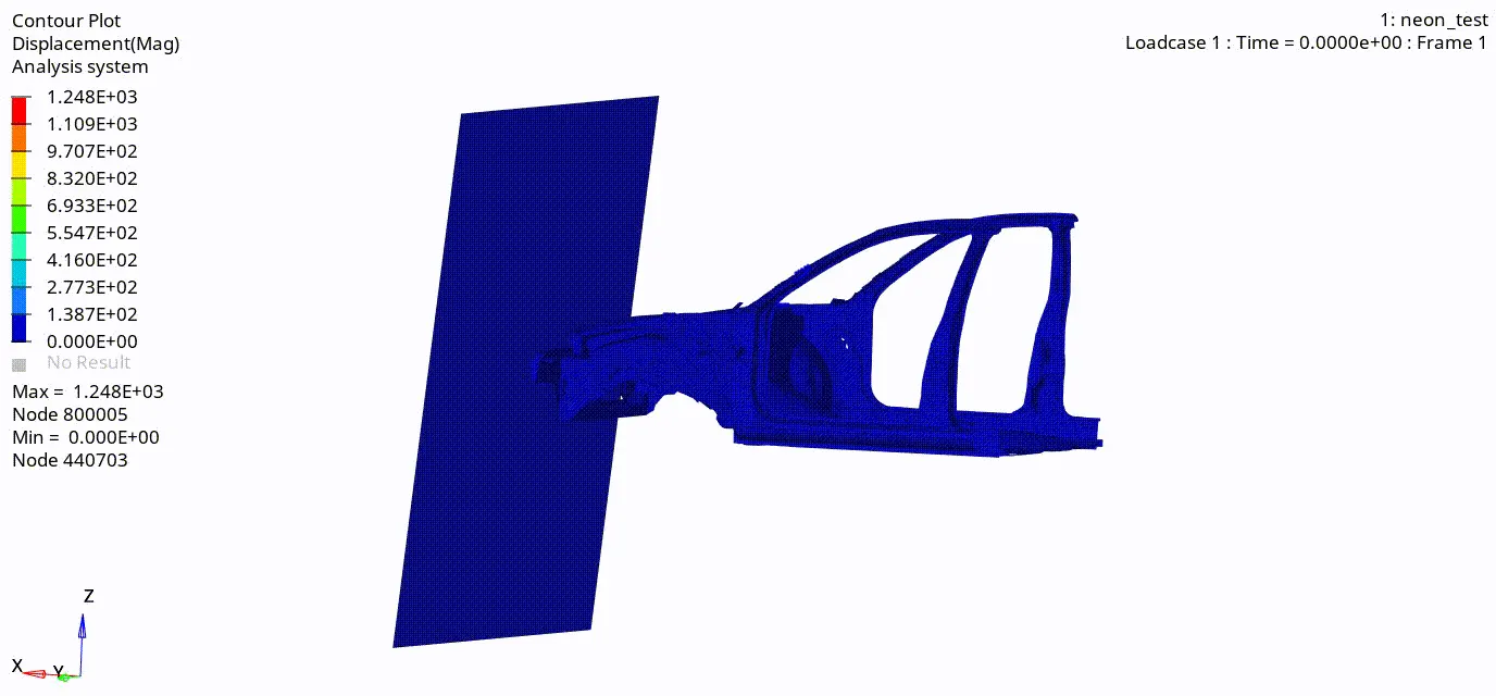
- From the above simulation, we can see that the deformation is starting to take place from the bumper component. since this is the component that is coming in
contact first. And here in bumper some amount of kinetic energy will get stored in internal energy as deformation take place. - After that remaining Energy will transfer to the further components which side rails and hence side rails start deforming and it will also absorb some
amount of energy. - Then Shotgun start deforming with and it will also absorb some amount of energy then finally A-Piller will deform.
- So according to the above discussion, we can understand that all the impact should absorb within the front section means before the passenger compartment.
- Deformation we can see that is not proper and realistic means BIW is kind of going down is just because there no chassis and suspension and wheel
system present in this model.
similarly for Von-mises:
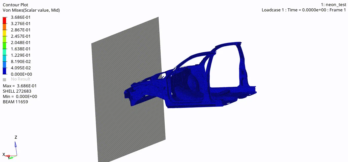
- Stress distribution over the model is quite good as we can see there are only a few regions in the bumper system that have stress concentration.
Otherwise, stress is distributed all over the BIW model.
2. Plot the graphs using Hypergraph-2D
Energy graph:
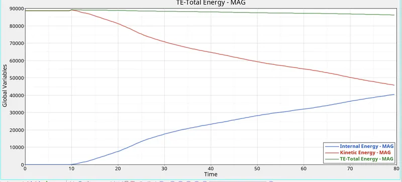
Internal Energy:-
At time t=0 internal energy will be zero, and as impact begins the amount of force causing the stress due to which strain start taking place and
deformation happens.
So due to deformation some internal energy will start storing within the body and keep increasing as deformation increases in the body.
Hourglass Energy:-
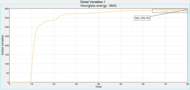
- Since we already used shell parameters, instead of that we observe some amount of hourglass energy.
- This hourglass happens in some region where goes below the given timestep due to stress concentration in course mesh.
- For that, we particularly work on that region to refine the mesh.
Sectional Forces:
In Shotgun:
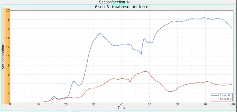
The maximum force in the shotgun is 18.45KN.
In A-Pillar: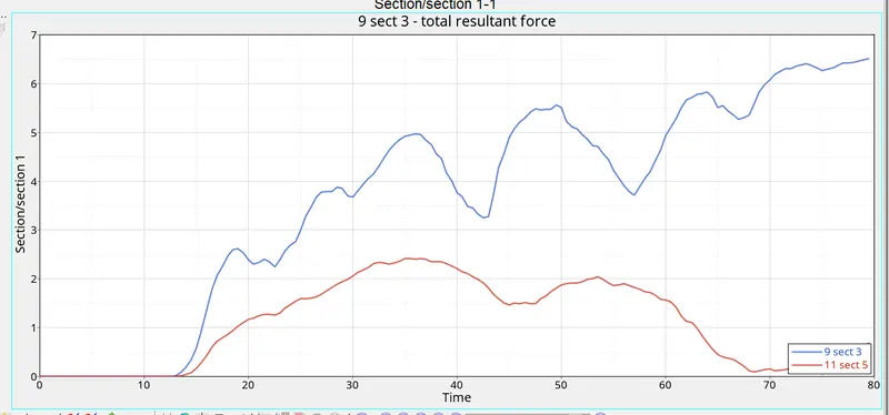
- The maximum force in the A-pillar is 6.5KN.
In Rails:
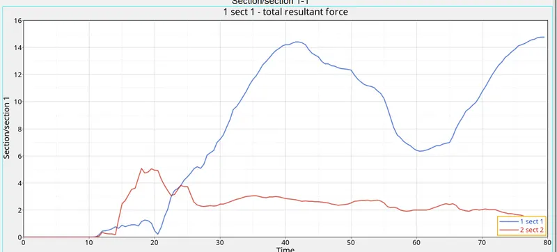
- The maximum force in the Rails is 14.76KN.
In Bumper:
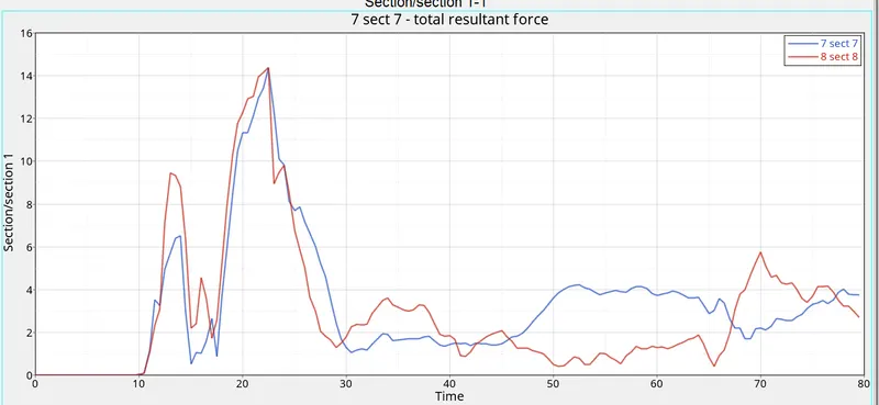
- The maximum force in the bumper is 14.39KN.
Acceleration in B-pillar: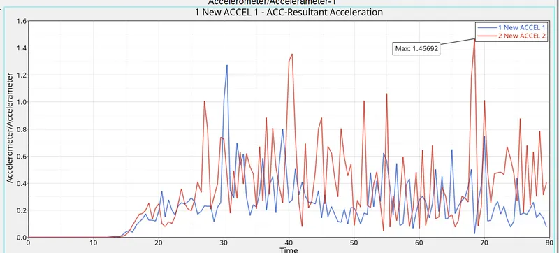
- The maximum acceleration achieved is 1.46mm/ms2.
The intrusion at nodes 66695 and 66244:
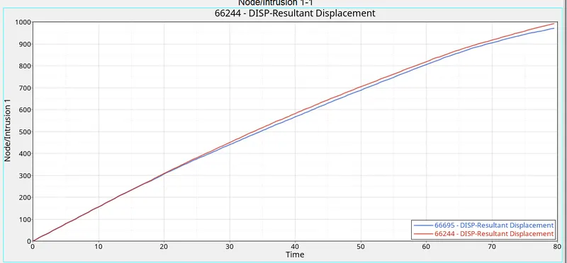
- The maximum displacement for node 66695 is 971 mm.
- The maximum displacement for node 66244 is 992 mm.
Result:-
- Mass balancing is done for the given BIW for a final value of 700kg.
- Created Typ-7 Interface contact for BIW self contact.
- Created rigid wall with friction value as given.
- Timestep value is given for all types of elements and contacts.
- Initial velocity is also given to the BIW body.
- An intrusion spring is created to measure the deformation or to ensure safety for the passenger leg area.
- The accelerometer is installed at the base of the B-Pillar.
- All TH files are requested for output and then run the model checker.
- Run the simulation and post-processed in hyper view and hypergraph.