Assignment 6
Q1) List down different TC and locate examples from GT Power
A turbocharger, is a turbine-driven, forced induction device that increases an internal combustion engine's efficiency and power output by forcing extra compressed air into the combustion chamber.
these are classified into 6 different types namely:
- Single-Turbo
- Twin-Turbo
- Twin-Scroll Turbo
- Variable Geometry Turbo
- Variable Twin Scroll Turbo
- Electric Turbo
- Single-Turbos
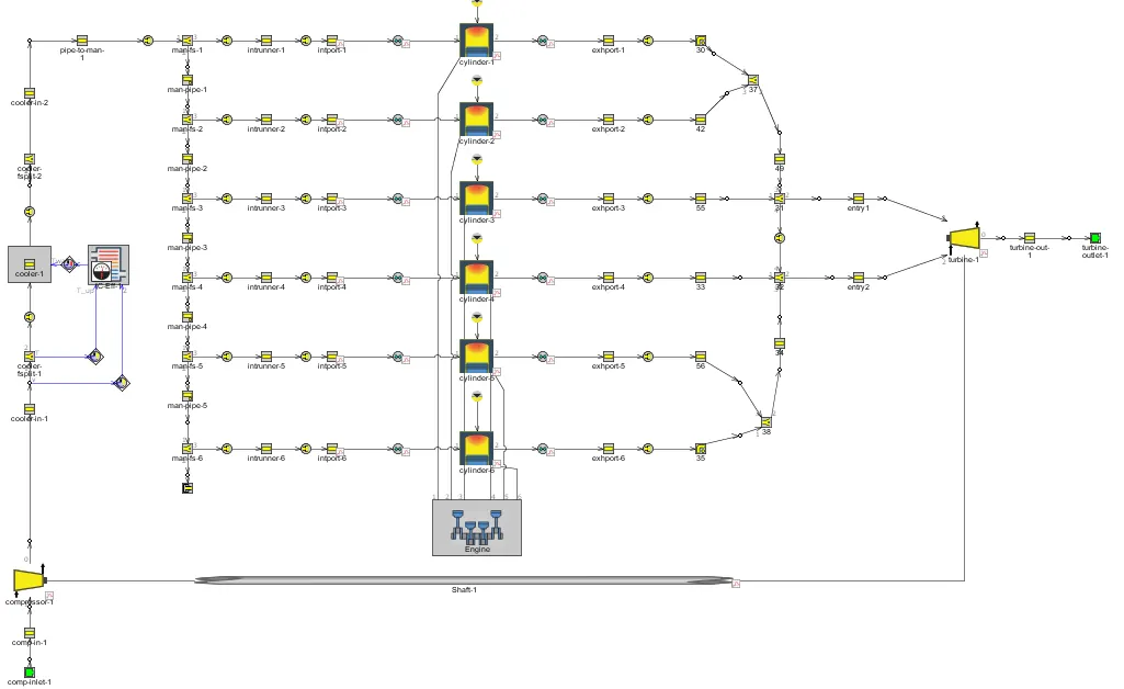
Single turbochargers are what most people think of as turbos. By differing the size of the elements within the turbo, completely different torque characteristics can be achieved. Large turbos provide higher levels of top-end power, whilst smaller turbos can spool faster and provide better low-end power. They are a cost-effective way of increasing engine power and efficiency, and as such have become increasingly popular, allowing smaller engines to increase efficiency by producing the same power as larger naturally-aspirated engines, but with a lower weight. They do however tend to work best within a narrow RPM range, and drivers will often experience ‘turbo-lag’ until the turbo starts to operate within its peak rev band.
- Twin-Turbo
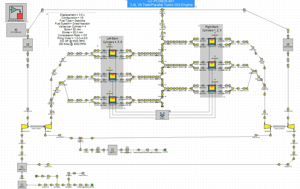
As the name implies twin-turbos mean adding a second turbocharger to an engine. In the case of V6 or V8 engines, this can be done by assigning a single turbo to work with each cylinder bank. Alternatively, one smaller turbo could be used at low RPMs with a larger turbo for higher RPMs. This second configuration (known as twin sequential turbocharging) allows for a wider operating RPM range, and provides better torque at low revs (reducing turbo lag), but also gives power at high RPMs. Unsurprisingly, having two turbos significantly increases the complexity and associated costs.
- Twin-Scroll Turbo
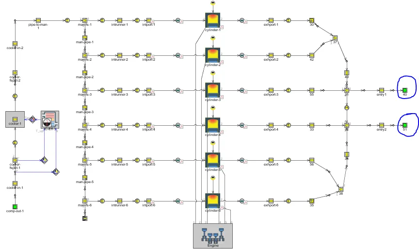
Twin-scroll turbochargers require a divided-inlet turbine housing and exhaust manifold that pairs the correct engine cylinders with each scroll. independently. For example, in a four-cylinder engine (with a firing order 1-3-4-2), cylinders 1 and 4 might feed to one scroll of the turbo, while cylinders 2 and 3 feed to a separate scroll. This layout provides more efficient delivery of exhaust gas energy to the turbo, and results and helps provide denser, purer air into each cylinder. More energy is sent to the exhaust turbine, meaning more power. Also, the vibrational effects of the engine can also be eliminated to an extent.
- Variable Geometry Turbocharger (VGT)
Typically, VGTs include a ring of aerodynamically-shaped vanes in the turbine housing at the turbine inlet. VGTs are limited in production (though fairly common in diesel engines) as a result of cost and exotic material requirements. Internal vanes within the turbocharger alter the area-to-radius (A/R) ratio to match the RPM. At low RPM, a low A/R ratio is used to increase exhaust gas velocity and quickly spool up the turbocharger. As the revs climb, the A/R ratio increases to allow for increased airflow. The result is low turbo lag, a low boost threshold, and a wide and smooth torque band
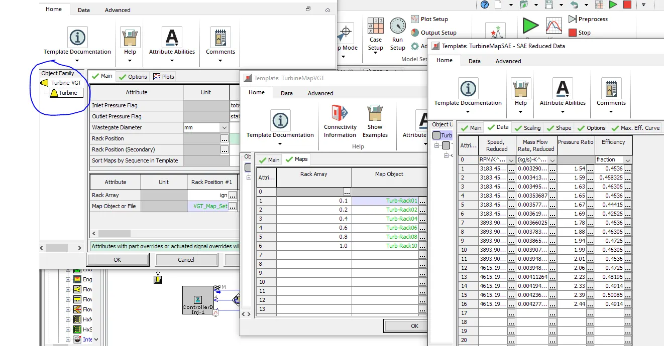
Here the rack position for a different angle of attacks is mentioned.
- Variable Twin-Scroll Turbocharger (VTS)
As the name suggests a VTS turbocharger combines the advantages of a twin-scroll turbo and a variable geometry turbo. It does this by the use of a valve that can redirect the exhaust airflow to just a single scroll, or by varying the amount the valve opens can allow for the exhaust gases to split to both scrolls. The VTS turbocharger design provides a cheaper and more robust alternative to VGT turbos, meaning it is a viable option for petrol engine applications.
- Electric Turbochargers
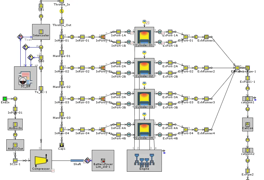
An electric turbocharger is used to eliminate turbo lag and assist a normal turbocharger at lower engine speeds where a conventional turbo is not most efficient. This is achieved by adding an electric motor that spins up the turbo’s compressor from start and through the lower revaluations until the power from the exhaust volume is high enough to work the turbocharger. This approach makes turbo lag a thing of the past, and significantly increases the RPM band within which the turbo will efficiently operate. So far, so good. It appears that electronic turbos are the answer to all the negative characteristics of conventional turbochargers, however, there are some disadvantages. Most are around cost and complexity, as the electric motor must be accommodated and powered, plus also cooled to prevent reliability issues.
Explore tutorial number 6 and 7
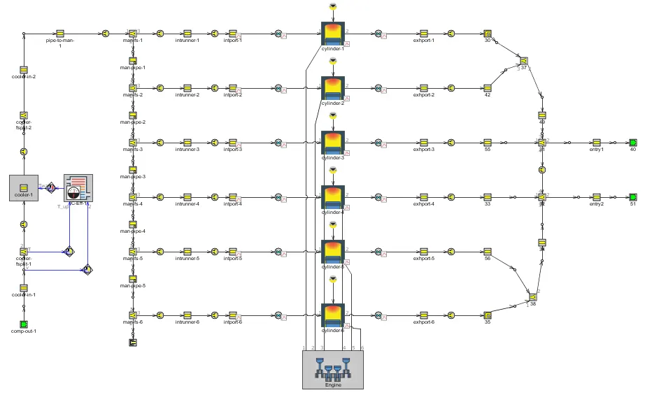
Example 6, is a GT model file of a 6Cylinder diesel engine, fitted with a turbocharger. Here we have used a twin-scroll turbocharger as we have 6 cylinders and sending all the exhaust gases to the turbocharger through one port may cause issues.
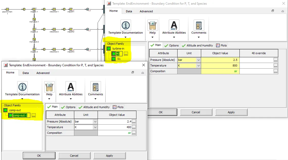
Moreover, instead of modeling the turbine and compressor as separate entities, we have just mentioned the end conditions of both turbine and compressors as inputs.
Example 7:
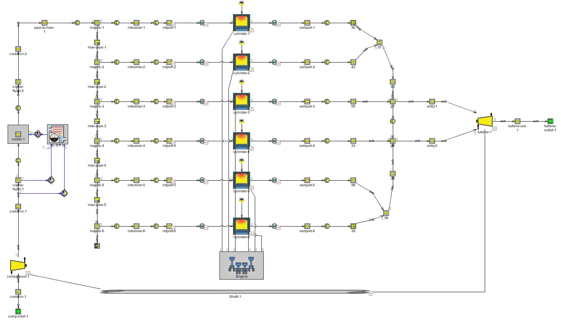
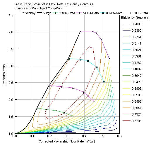
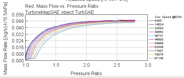
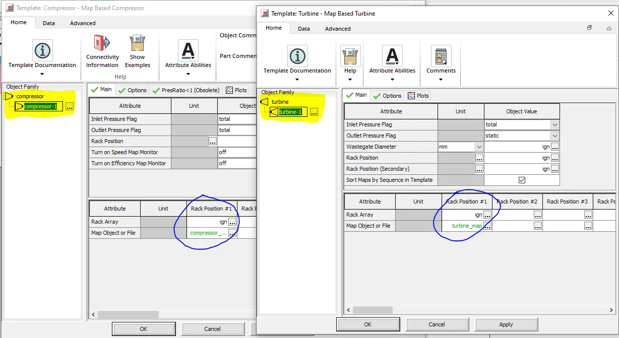
This model is also a 6cylinder twin scrolled turbocharged diesel engine. But unlike in example 6, here we have modeled both the turbine and compressor. Also as a result of which we can input both the compressor and turbine maps. Here we have even provision of adding rake angles, in the case of variable gate turbocharger.
Compressor map:
Turbine map:
We input the above compressor and turbine data in the compressor and turbine data tabs.
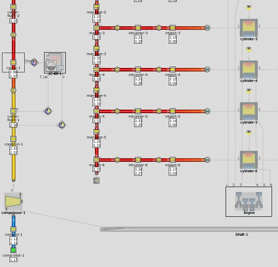
The above-given plot is an average density plot. Here we can see how the density of atmospheric air is changing from 1.1 at the compressor inlet to 3.37 at the inlet manifold. As the density of the air increases, we can add more mass of air in a given volume, thereby increasing the amount of fuel intake. This way we can increase the power of the engine.
Plot operating points on compressor and turbine maps
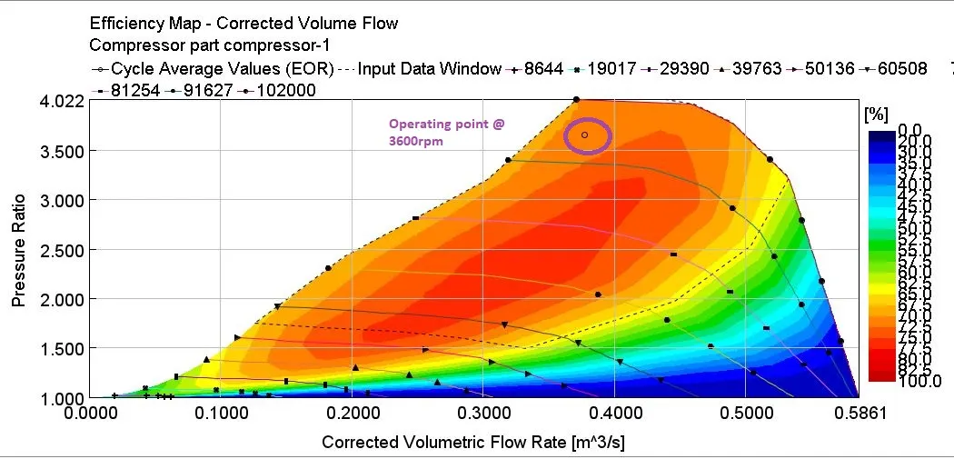
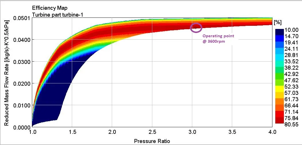
- Here the operating point is nearer to the excess rotor speed zone, which is not preferred as it can cause mechanical failure to the rotor blades. As a solution to this either we can reduce the fueling or reduce the speed at which the rotor is functioning. There is also a provision of using a higher compressor, which can handle high-pressure ratios.
In which application Variable Geometry Turbine is beneficial?
Variable geometry turbochargers mean variable A/R ratios. The only plausible way of getting a variable A/R ratio is by varying the cross-sectional area A of the exhaust gas flow. The radius R will always be constant.
Compared with fixed geometry turbochargers, variable geometry turbochargers are designed to:
- increase intake air boost pressure at low engine speed
- improve the response time of the turbocharger during transient engine operation phases
- increase the availability of the maximum engine torque
- prevent over-boosting at high engine speed
- reduce exhaust gas emissions and improve fuel economy.
The benefits of variable geometry turbines over wastegate turbines include
- no throttling loss of the wastegate valve;
- higher air-fuel ratio and higher peak torque at low engine speeds;
- improved vehicle accelerations without the need to resort to turbines with high pumping loss at high engine speeds;
- potential for lower engine ΔP (the difference between the exhaust manifold and intake manifold pressures);
- control over engine ΔP that can be used to drive EGR flow in diesel engines with High-Pressure Loop (HPL) EGR systems;
- a better ability to cover a wider region of low BSFC in the engine speed–load domain;
- ability to provide engine braking;
- ability to raise exhaust temperature for after-treatment system management.
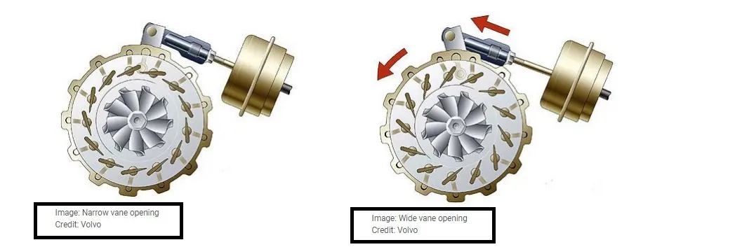
fig: opening and closing of vanes of variable geometry turbocharger
Explore example- Diesel VGT EGR and understand the modeling part
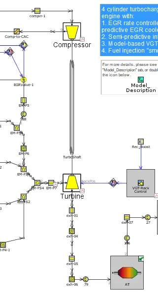
The example 'Diesel_VGT_EGR' demonstrates several modeling concepts important for automotive diesel engines, including variable geometry turbine, boost control, intercooler, EGR circuit with cooler and EGR rate control, injection limiting for smoke control, and exhaust after-treatment device modeling (geometry only, no chemistry).
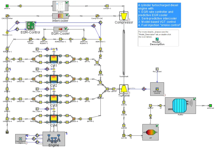
The engine is a 4-cylinder, four-stroke, direct injection, 2L diesel engine. The Combustion is modeled by the DIPulse method, a predictive combustion model using the detailed injection profiles. In-cylinder heat transfer is modeled using the Woschni model.
The EGR System
The model includes an exhaust gas recirculation (EGR) system to transport exhaust gases from the exhaust manifold back to the intake manifold. The EGR flow is driven by a positive pressure difference between the exhaust manifold and intake manifold and is controlled by an orifice connection (EGR-valve). The EGR-valve diameter is imposed by an actuator and is determined automatically by a 'ControllerEGRValve' part to achieve a target EGR fraction. The desired EGR fraction is mapped as a function of engine speed and the requested BMEP. EGR rates in the model are as high as 40% at some operating points. Because of the high EGR rates, it is desirable to cool the EGR gases using a heat exchanger (EGR-cooler). When the pressure drop across the EGR system is not sufficient to achieve the target EGR rate, throttle in the intake system, controlled by a PID controller, increases the pressure difference. This controller is only active if the EGR-valve is fully open.
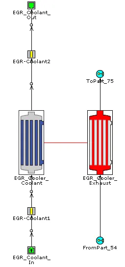
The Turbocharger and Boost Controller
The turbocharger in this model contains a fixed geometry compressor and a variable geometry turbine (VGT). For the VGT, there are 5 different sets of turbine map data entered at each of 5 VGT rack positions. The VGT rack position is determined by a control system to achieve a target boost pressure upstream of the intake manifold. The boost pressure is sensed and is then filtered using a 'MovingAverage' part to produce an average pressure signal. The model-based controller compares the sensed boost pressure to the target boost pressure and then adjusts the VGT rack position accordingly.
Results:
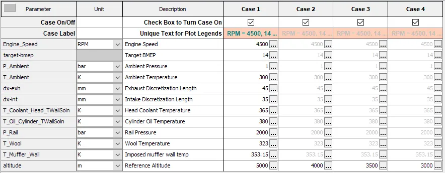
Case setup:
Compressor map:
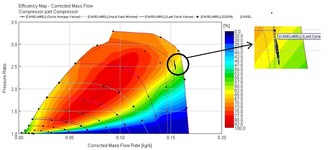
We can see from the compressor map, that with the decrease in altitude the power required by the compressor to compress the air reduces. As a result of which the pressure ratio reduces.