Assignment 11
1. Tutorial- single cyl DI add case 2 with discretization length 0.1 mm for intake runner and compare with default case 1
-
- Parameters-Torque, BSFC, max cylinder pressure
- simulation time
- GT Model:
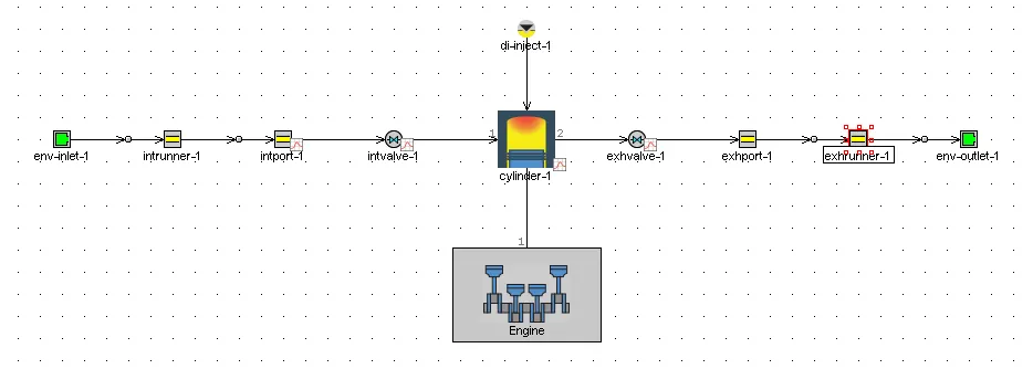
- Engine model: Here the bore diameter is 100mm. Usually, we define the intake runner as 0.4 times the bore diameter and the exhaust runner as 0.55 times the bore diameter. The exhaust has been defined with more discretization length, because the gases coming out of the engine is of high temperature, as a result of which its density decreases, thereby reducing the velocity of gases.
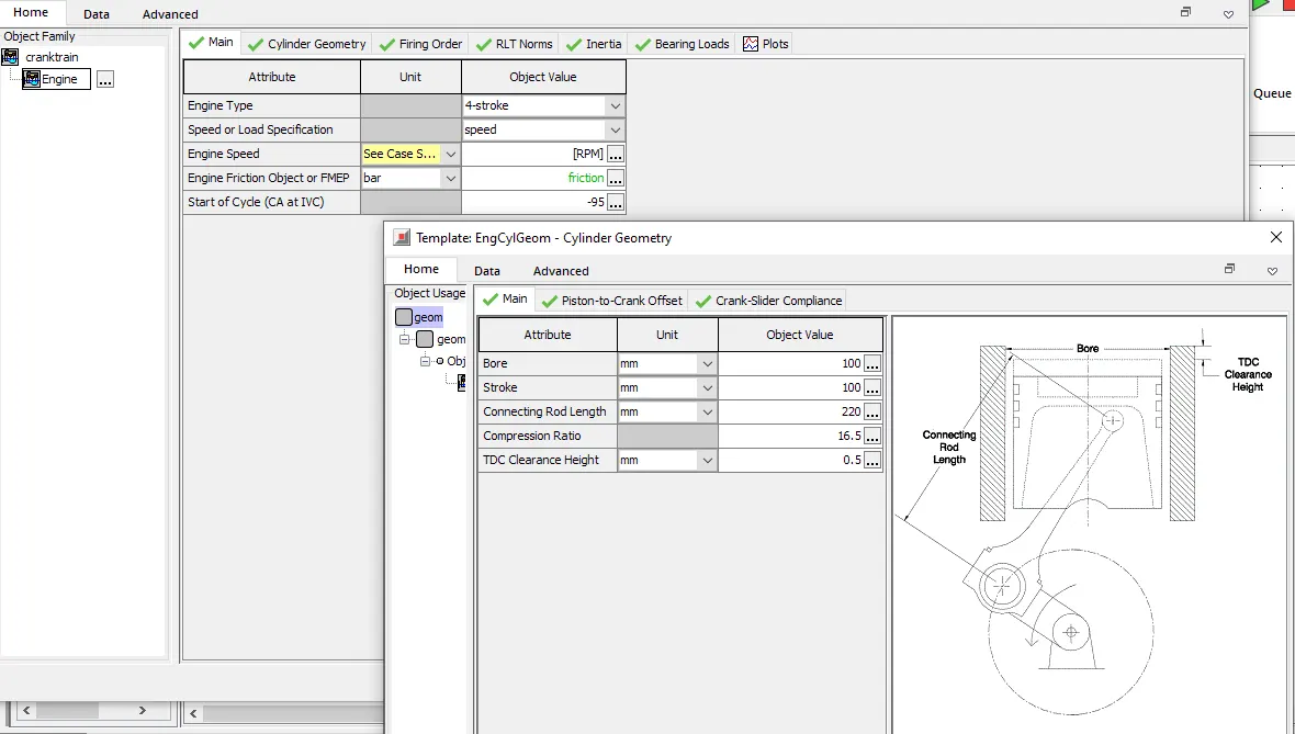
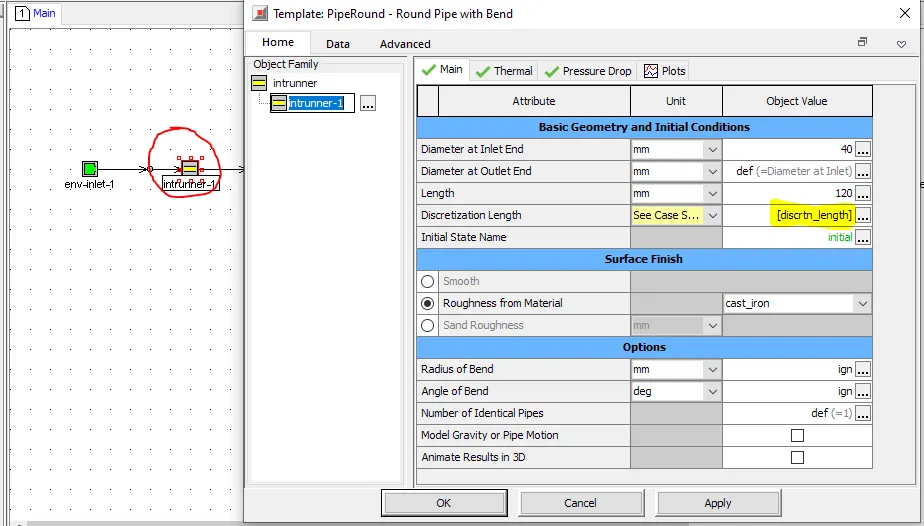
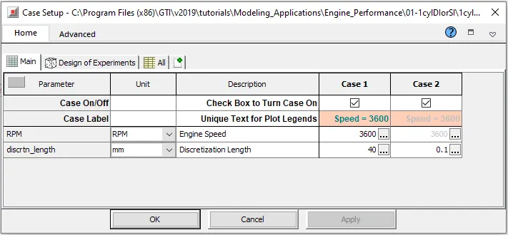
Defining the discretization length as a parameter.
Case setup:
Results:
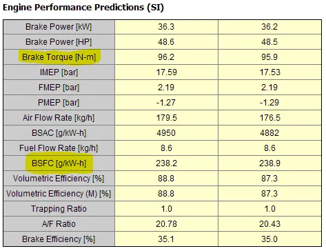
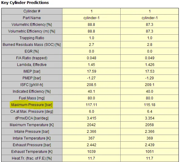
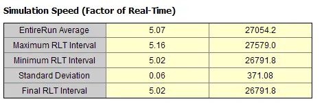
The difference b/w the values of Brake torque and BSFC is 0.3 N-m and 0.7 g/kW-hr respectively, while that of in-cylinder pressure is 1.93 bar. Even though this difference in values is not large enough to justify the simulation time difference of 27049. Just going with a discretization length of 0.1mm does not give much difference considering the simulation time it had taken.
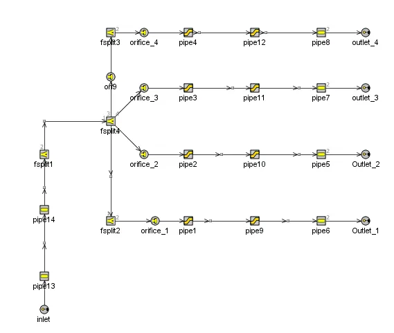
2. Explore tutorial no 2 (GEM3D) - “Building intake manifold from STL model”
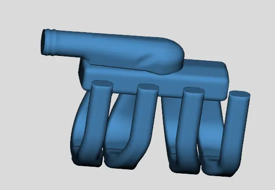
- Step1: importing the Intake manifold '.Stl' file.
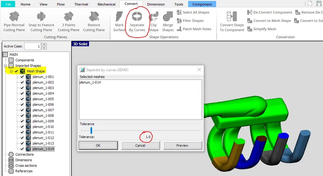
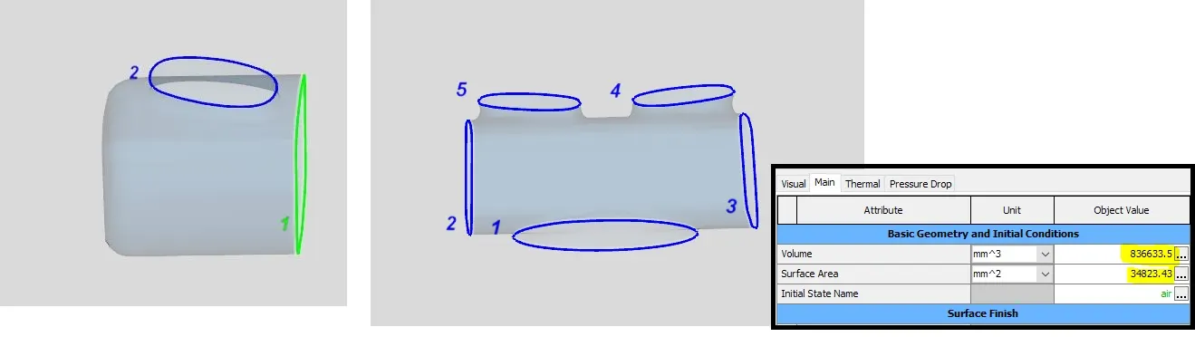
- Step:2: Splitting the model based on the curves, so that the entire planum can be split into different small parts. There is an option for adjusting the tolerance value also, which can be varied depending on our needs.
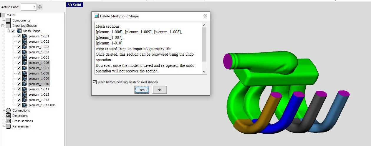
Step 3: Deleting the closed openings, so that it can be connected to a circuit.
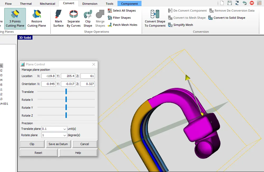
- Step4: Splitting the runner from the plenum, for the easy discretization of the model.
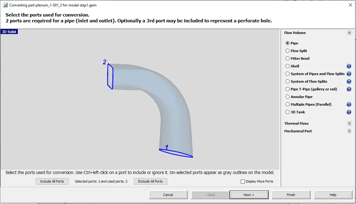
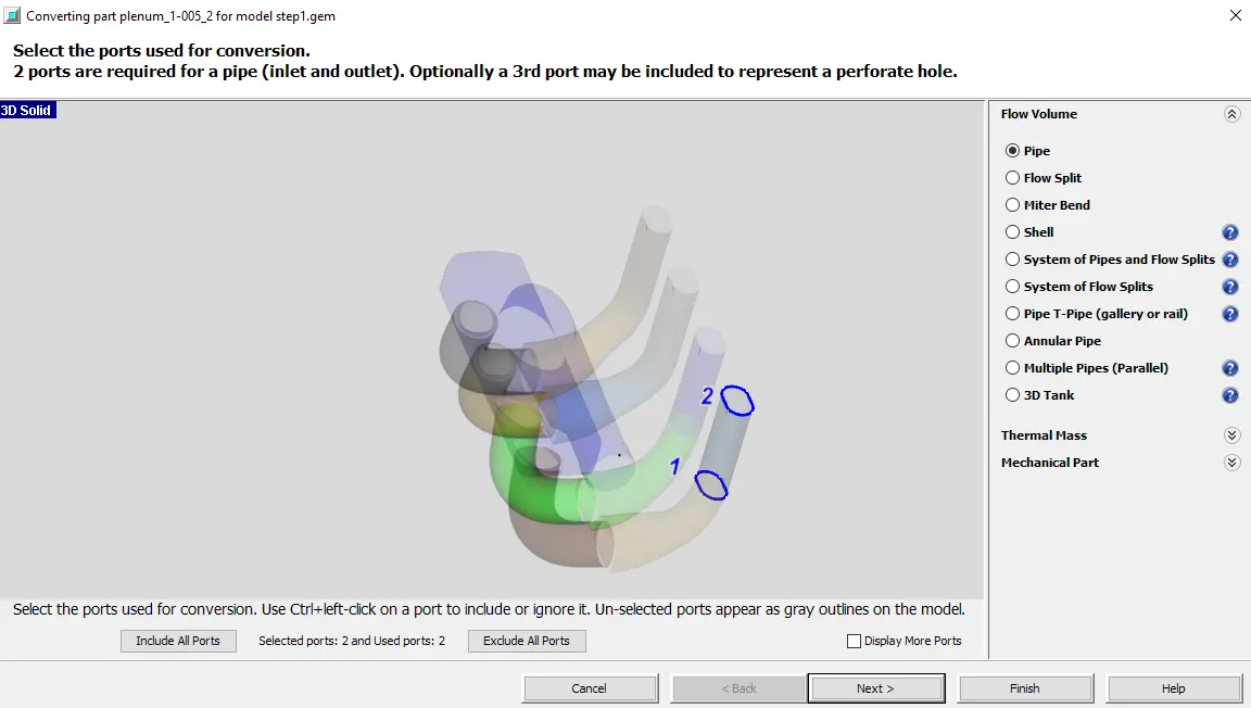
- Step5: Converting the shape into the flow component. Care should be taken so that the flow direction is matching with the model.
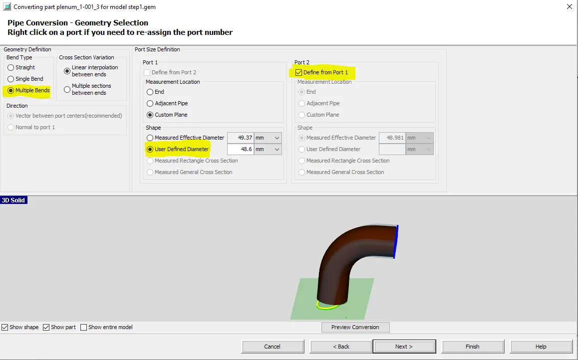
Since the pipe is not a straight pipe, we define it as a bend pipe, and also gives the average dimensions.
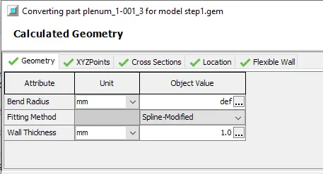
The thickness of the pipe is defined in the next tab.
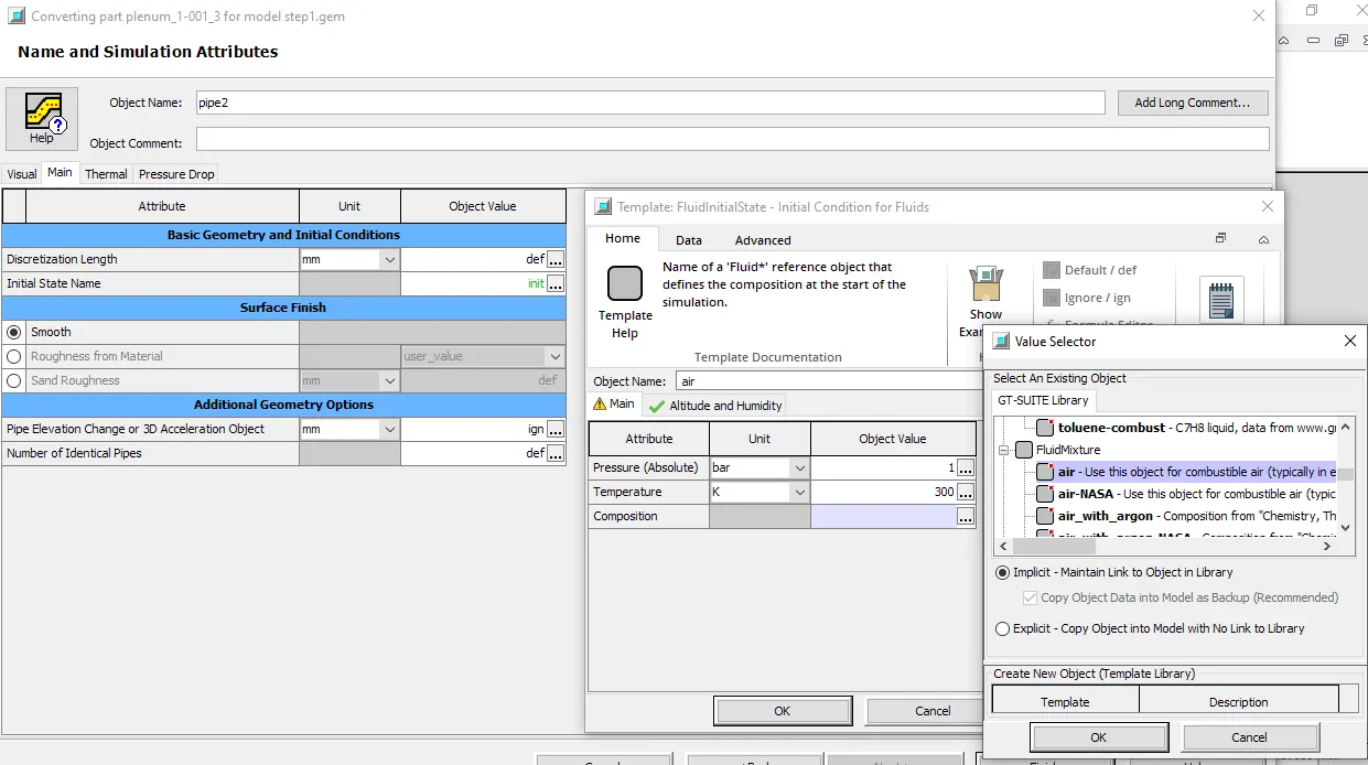
The properties of the flowing substance and its initial conditions are defined also defined. In this case, it is air.
Similarly, convert all other components,
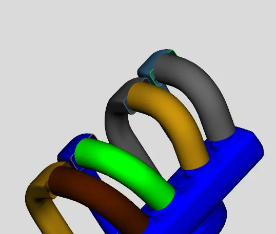
Similarly, convert all other parts, by assuming the nearest dimension, which can fit the entire model.
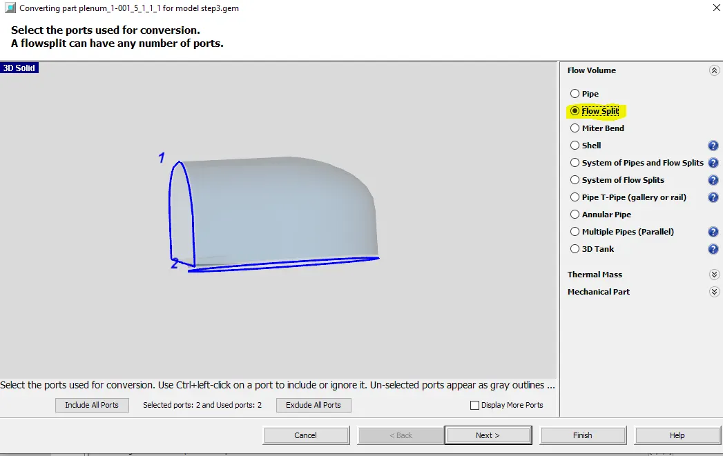
For shapes which is not a straight or bend pipe, we can define it as a flow split.
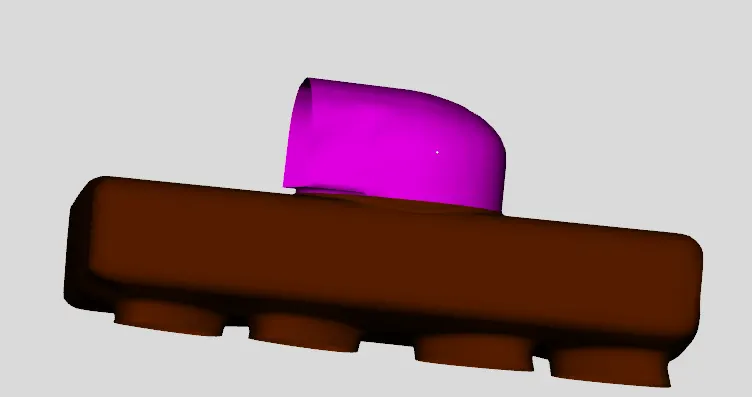
Once the model is simplified, now it's time to fill the gaps and make the geometry watertight.
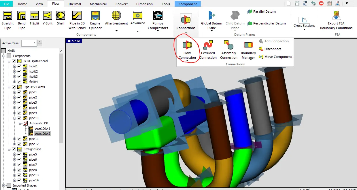
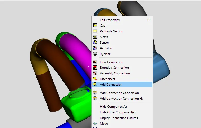
- Step6: Joining the components
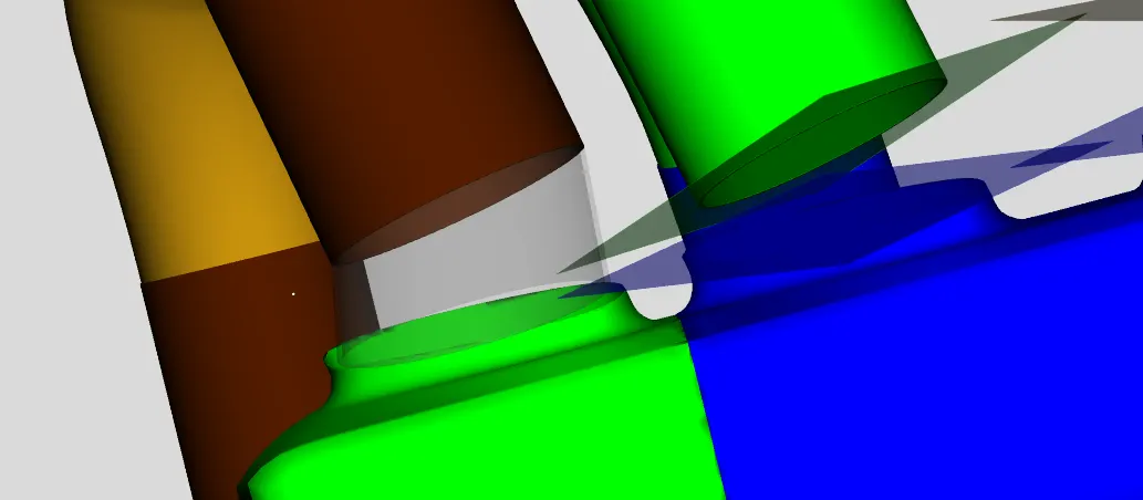
Extrude flow command also, can be used if there is plenty of gaps b/w the pipes.
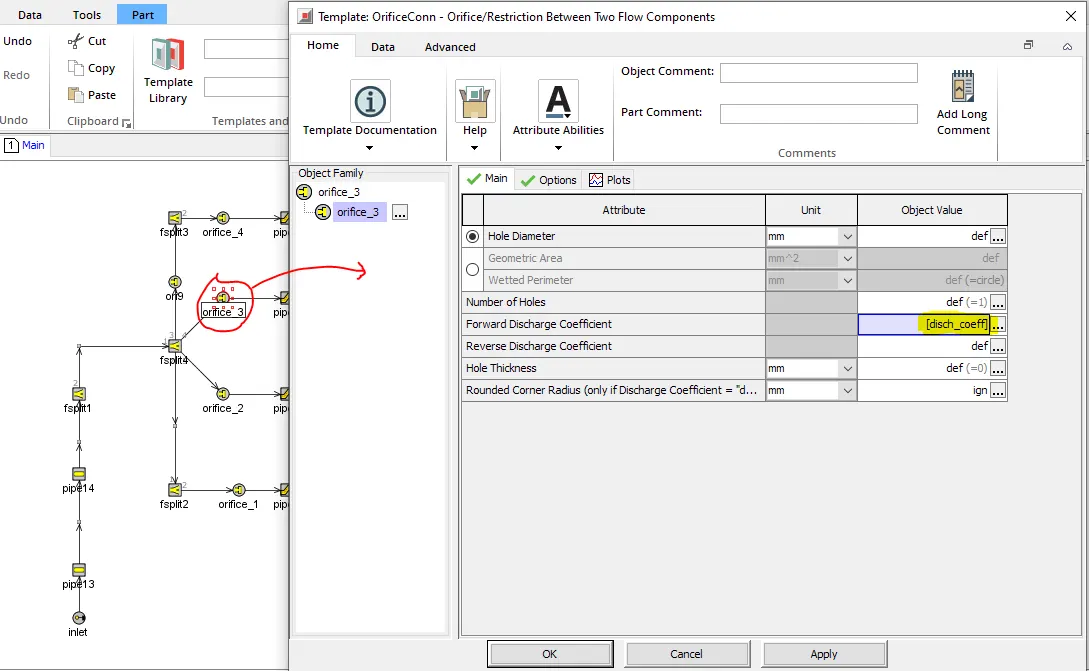
- Step 7: Naming the connections and defining the flow coefficients at the smooth junctions.
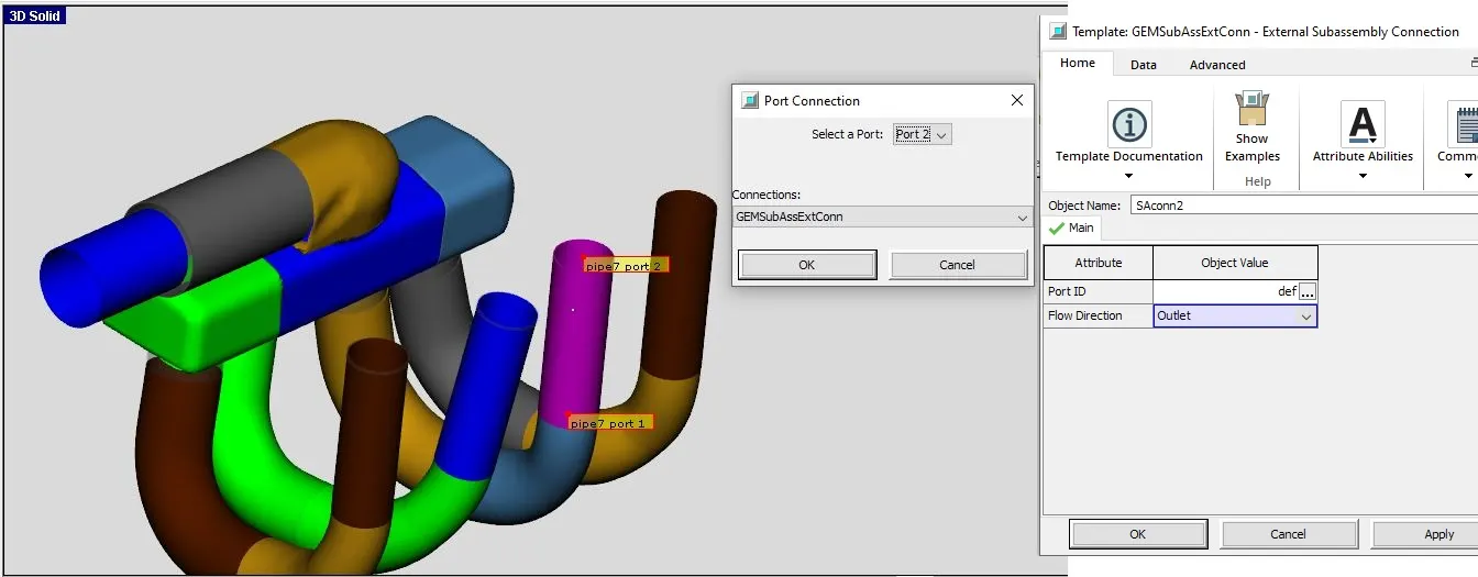
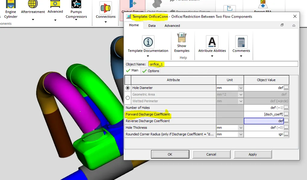
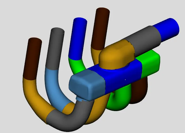
Final model after simplification and naming of all parts.
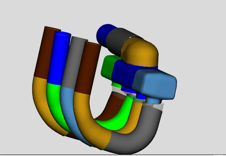
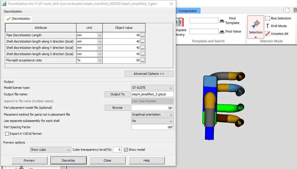
- Step8: Discretization and exporting to GT
Since it is an inlet manifold we discretize 0.4 times the bore diameter( assuming bore diameter is 100mm)
GT Model: